00-SF on the web
00-SF is also known as 4-SF or "EM minus 2" - from an original idea by Roy Miller in 1973
For EM add 2.0mm to all relevant dimensions below.
See Supply of Gauge Tools below for details of how to obtain track gauges for building 00-SF track.
Other pages: 00-SF Dimensions History of 00-SF Setting 00 Wheels for good running
00-SF v Peco

This diagram above shows the huge improvement in the appearance of the crossing (frog) when the narrower 00-SF flangeways are used. You can see from the orange areas how much the gap area in front of the vee is visually reduced. Although visually the reduction in the length of this gap is the most noticeable difference, it is the reduction in the width which brings about the big improvement in running quality. The width of this gap at its widest point must be less than the width of a wheel. It is then physically impossible for a wheel to "drop in" -- it remains fully supported on the rails as it runs through the crossing. All 00 wheels are wider than the gap for 00-SF. But many are narrower than the much wider gap in the Peco turnout, and bumpy running is inevitable as they run across the unsupported area.
Dimensions for 00-SF
| TRACK: | ||||
| A | check gauge | 15.2 mm | MINIMUM | This dimension must not be less than 15.2mm. There is no maximum, but if other dimension limits are met it will not be possible to exceed 15.2mm significantly. |
| B | crossing flangeway gap | 1.05 mm | MAXIMUM | If prototypical blunt-nose vees are used, this dimension must not exceed 1.05mm. There is no minimum, but it will not be possible to make it significantly less than 1.0mm if other dimension limits are met. This dimension is normally set as close as possible to 1.0mm by making it a close fit on the 1.00mm gauge shim. |
| E | check span | 14.25 mm | MAXIMUM | The span across the wing rail and check rail must not exceed 14.25mm. There is no minimum. |
| C | track gauge | 16.2 mm | MINIMUM | This dimension must not be less than 16.2mm. It can be widened where necessary on sharp curves. |
| WHEELS: | ||||
| back to back | 14.3 mm | MINIMUM | Wheel spacing must not be closer than this, otherwise the wheels may jam or bind across the check span. | |
| back to effective flange | 15.2 mm | MAXIMUM | This dimension must not exceed 15.2mm otherwise wheel flanges may strike the crossing nose and bump or derail. | |
| wheel width | blunt-nose crossings: 2.3 mm sharp-nose crossings: 2.1 mm |
MINIMUM | If wheels are narrower than this there is a risk they may drop into the crossing gap. There is no maximum. | |
| flange thickness | 0.8 mm | MAXIMUM | Must not exceed 0.8mm to clear the flangeway gap, and to provide a running clearance between the rails on plain track. There is no minimum. | |
A is the check gauge. It is the most critical dimension in pointwork. If this dimension is too small, wheels running from left to right can hit the nose of the vee and very likely derail, or at least bump. If this dimension is too large, the wheel backs will bind or jam on the check rail. To make sure it's correct, the check rail is set using check gauge tools.
For 00-SF and 00-BF this dimension should be 15.2mm. You can use the same check gauge tools for both these standards, and also for 00-MF and 00-IF (they are all running the same wheels).
B is the crossing flangeway gap. It's also important. If this dimension is too small, the wheel backs will bind or jam on the wing rail. If this dimension is too large, the gap in front of the nose of the vee will be too wide, and the wheels may drop into it with a bump. This gap is set using a small piece of metal shim called a crossing flangeway gauge shim. For 00-SF it should be 1.0mm thick. For 00-BF it should be 1.3mm thick.
C is the track gauge. It shouldn't be less than the specified dimension, but it can be wider. It is often widened on sharply curved track to ease the running of long-wheelbase vehicles. The track gauge is normally set using roller gauge tools, or alternatively using a 3-point gauge tool, which automatically widens the track gauge on sharp curves. For 00-SF this dimension shouldn't be less than 16.2mm. For 00-BF it is normally 16.5mm.
D is the check rail gap. The width of this gap doesn't matter, providing it is wider than the wheel flanges. It's whatever you end up with after setting A and C correctly.
(But where the check rail is combined with a wing rail in complex formations such as a tandem turnout -- i.e. in parallel-wing V-crossings -- it must be the same as B.)
E is the check span. It is not usually necessary to set this dimension directly if the gauges are used correctly. For 00-SF this dimension shouldn't be more than 14.25mm. For 00-BF this dimension shouldn't be more than 14.0mm.
Settings for 00-SF (and 00-BF)
For EM add 2.0mm to these dimensions.
For best-running 00 models:
a. Measure the width of the wheels.
b. RTR wheels will be around 2.8mm wide. Assume the flanges are 0.8mm thick and set the back-to-back to 14.4mm.
c. Romford/Markits wheels will be 2.5mm wide. Assume the flanges are 0.7mm thick and set the back-to-back to 14.5mm.
d. Kit wheels such as Alan Gibson / EMGS will be around 2.3mm wide. Assume the flanges are 0.6mm thick and set the back-to-back to 14.6mm.
e. For 00-SF make sure no wheels have back-to-back less than 14.3mm.
f. For 00-BF make sure no wheels have back-to-back less than 14.1mm.
g. If you want to use the same back-to-back for everything, make it 14.4mm. Kit wheels won't run so smoothly, but they will run.
Adding some detail to that:
RTR models such as Hornby and Bachmann normally have wheels 2.8mm wide conforming to the NMRA RP25/110 profile with flanges 0.8mm thick. They should be supplied set to 14.4mm back-to-back, which is also the DOGA-Intermediate setting -- see: DOGA wheel standards
Sadly the manufacturers don't always have the best quality control. For 00-SF, such RTR wheels should be 14.4mm maximum, 14.3mm minimum, back-to-back.
14.4mm back-to-back gauges are available from DOGA shop for DOGA-Intermediate.
Most modern RTR models will be found to run fine on 00-SF straight from the box. But there is always the possibility that you will get a rogue wheel set which needs adjusting as above (or ideally returned to the supplier for replacement).
----------
Locomotive wheels from Markits/Romford are 2.5mm wide with flanges 0.7mm thick. These are the traditional BRMSB "scale 00" wheels which should be set to 14.5mm back-to-back. Using the Markits/Romford squared axles you don't have much choice over this. For 00-SF, these wheels should be 14.5mm maximum, 14.3mm minimum, back-to-back.
14.5mm back-to-back gauges are available from Markits
----------
Rolling stock kits such as Parkside Dundas are usually supplied with Alan Gibson or similar wheels which are either to the EMGS profile or the very similar NMRA RP25/88 profile. These wheels are 2.3mm wide with flanges 0.6mm thick. For 00-SF, these wheels should be 14.6mm maximum, 14.3mm minimum, back-to-back. Ultrascale wheels are similar.
 These wheels may be supplied set to 14.7mm or 14.8mm back-to-back which is intended for the DOGA-Fine standard and is too wide for good results on 00-SF or 00-BF. They should be adjusted as above.
Some non-UK "code 88" wheels have flanges thicker than 0.6mm, and should therefore be treated as RTR wheels, as above.
Summarising the above, if you are not sure of which wheels you are dealing with, measure the width of them:
For 00-SF:
Wheels 2.8mm wide -- back-to-back 14.4mm MAX.
Wheels 2.5mm wide -- back-to-back 14.5mm MAX.
Wheels 2.3mm wide -- back-to-back 14.6mm MAX.
For 00-SF the MIN back-to-back is 14.3mm for all of them.
For 00-BF the MIN back-to-back is 14.1mm for all of them.
But for best results, ignore your back-to-back gauges. If you have 00-SF check gauges you can make yourself a simple wheel checking fixture which I described on RMweb recently. This not only gives better results, it ensures your wheels are matched to the actual track you will be building.
Here's the link for that -- see this and subsequent posts on RMweb: 00-SF wheel setting fixture

Thanks to Dave (Acklam) for this picture.
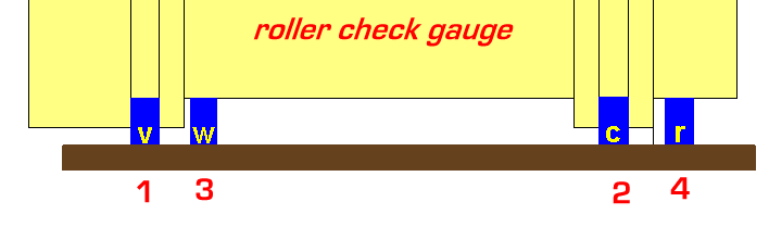
1. Fix this rail first. It represents the crossing vee. There is a flat on the check gauge so that it can be used where the vee won't fit in the slot.
2. Fix this rail second, using the check gauge tool. It represents the check rail.
3. Fix this rail third, using the 1.0mm shim. It represents the wing rail. it doesn't engage with the check gauge tool.
4. Fix this rail last, anywhere you like. Its sole purpose in testing the wheels is to support the wheel. It represents the opposite running rail. A good way to identify it in future is to fix it upside down, or make it longer or shorter than the other rails.
Mark which rail is which. Don't get rails 1. and 4. muddled up.
In using the fixture,
1. hold the back of one wheel against rail 2.
2. gently lower the other wheel onto rail 1.
3. the wheel flange should just clear the side of rail 1. without rubbing, but ideally leaving only a fraction of daylight showing between them.
4. the back of that wheel should easily clear rail 3.
With care, a testing fixture like this if accurately made is a better way of setting the wheels than using a back-to-back gauge, because it allows for different flange thicknesses, and the actual track you are building.

The diagram above shows an A7 turnout in 00-SF, radius 53". This is typically the size of turnout which a modeller in 00-SF might use in place of a Peco Large Radius turnout, radius 45". Both turnouts are shown truncated to the mid-point of a crossover. In 00-SF double tracks are closer together at 45mm centres (as prototype) than for Peco at 51mm centres, so that although the 00-SF turnout is an easier radius than Peco, it is actually slightly shorter to the crossover mid-point. The 00-SF turnout has had the lead length to intersection adjusted slightly in order to match the Peco turnout exactly (purple line). This is a screenshot from Templot .

The diagram above shows the nearest exact match to a Peco Large Radius turnout. It has a GWR 10ft curved switch and a 1:6 curviform V-crossing. That's not a common size, it was generated simply to get as close as possible in 00-SF to the Peco dimensions.

The diagram above shows the same turnouts printed out as a track construction template. The difference in appearance of the 4mm/ft scale UK-style timbering for 00-SF is very noticeable.
diagrams © Martin Wynne 2008
Supply of track gauge tools for 00-SF
Please note that these 00-SF gauge tools are no longer available from Brian Tulley.
Manufacture and supply has been transferred to C&L who now have them available.
See:
00-SF roller track gauges on C&L web site
00-SF 3-point track gauges on C&L web site
00-SF check gauges on C&L web site
**Please Note: Track Gauge design dimensions were derived from C&L Code 75 Bullhead Rail. However, rail (including Flat Bottom Rail) from other manufacturers (SMP, Marcway, Peco, Exactoscale etc.) may also suit.
Martin Wynne