Templot Club Archive 2007-2020
|
|||
| author | remove search highlighting | ||
|---|---|---|---|
|
posted: 11 Mar 2010 14:25 from: Dellboy
click the date to link to this post click member name to view archived images |
Hello I am about to start some point building, initally using copperclad sleepers (a first for me) for the hidden storage sidings and then using riveted sleepers for the rest of the trackwork. Code 75 rail with C&L flexitrack for the plain track. In the dim distant past I built points using rail soldered onto tacks driven in sleepers and then progressed onto the 'new' system of rivet/sleeper construction with whitemetal cosmetic chairs. That dates me a bit! My sequence used to be to set up the main stock rail as one continuous rail for the full length of the point followed by the Vee, then the turnout stock rail, then the wing rails through to the switches with the check rails going in last. For three -way points all the vees would be installed after the first stock rail (starting with the Vee furthest from the switches). Similar approach for diamonds, slips and for scissors crossovers but with the associated K angles/wing rails etc being built with the Vees after the first stock rail. All using the appropriate gauges of course. From what I've seen, current thinking advocates setting the Vee up first followed by the check rails and then stock rails. I cannot see the advantage of doing it this way as the slightest error in alignment of the Vee will result in overall misalignment of the point. My method of putting the stock rail in first anchors the overall alignment and the rest follows to suit. I should mention all my points are on transition curves. My question is to all you point builders out there is what is your experience, to Vee or not to Vee? And a second question; I have seen a method which initially appeals to me of using soldered rivets say every fourth/fifth sleeper with plastic cosmetic chairs in between. Has anyone had experience of this method? Derek |
||
|
posted: 11 Mar 2010 14:42 from: polybear click the date to link to this post click member name to view archived images |
Norman Solomon puts the stock rail in first..... HTH Brian |
||
|
posted: 11 Mar 2010 15:06 from: allanferguson
click the date to link to this post click member name to view archived images |
I had always been a dyed in the wool rivets and solder man, and it is undoubtedly strong and easily adjustable. However it undoubtedly the most mind numbingly tedious job I know to mark, punch, and rivet up all the sleepers. (As a Scottish pre - group modeller I use sleepered leads). Of late I have taken to functional plastic sleepers, in my case from C & L, and I have developed confidence in the method. Using the recommended Butanone solvent I have attached plastic chairs to ply sleepers, and have never had any come undone. In extremis I can with a craft knife carefully peel the chairs off without damage. The assembly is fragile until stuck down, and getting it off the template and onto the baseboard needs to be done with care. Temporarily soldering lengths of rail at right angles across the formation can help to hold it together, and the wife's hairdryer, used with discretion and permission, will to soften the double sided tape, making it easier to get the formation off. The difficult area is the crossing, with the vee and wing rails, which cannot be held together with sufficient accuracy by the plastic chairs. My practise now is to assemble the vee and wing rails on a brass baseplate equal in thickness to the chair depth. The brass can be trimmed with care and a cutting disc to the profile of the rails and becomes invisible in use. I use a separate home made jig and a lot of care for this, and the crossing assembly then becomes perfectly rigid, and is held in place by chairs on the extended rail ends, and by half chairs fixed around it later. I like stick to the method of straight stock rail first, then crossing, then curved stock rail, but sometimes in complex formations it's necessary to be imaginative!176_111006_020000000.jpg  It all seems to work for me! |
||
|
posted: 11 Mar 2010 15:58 from: Jim Guthrie
click the date to link to this post click member name to view archived images |
From what I've seen, current thinking advocates setting the Vee up first followed by the check rails and then stock rails. I cannot see the advantage of doing it this way as the slightest error in alignment of the Vee will result in overall misalignment of the point. My method of putting the stock rail in first anchors the overall alignment and the rest follows to suit. I should mention all my points are on transition curves. My question is to all you point builders out there is what is your experience, to Vee or not to Vee? Derek, I usually place the "V" first, especially on complex formations. The positions of the crossing noses dictate all the angles through the formation. If you place a stock rail just a natz out of gauge on the plan then the crossing nose will have to follow suit and that can reflect through onto other parts of the formation - or if you slide it forwards or backwards to get back to the same line of the diverging route from the already laid stock rail, then your nose could be out on the timbering. I'm just building a turnout at the moment and I've started with the "V" and I haven't found any problems in laying the "V". I normally use overlong pieces of rail when constructing the "V" which helps with the alignment, then chop off the rails to length when they are in place. Jim. |
||
|
posted: 11 Mar 2010 16:13 from: Alan McMillan
click the date to link to this post click member name to view archived images |
Hi All I've always started with the Vee. In a slip or diamond crossing, I'll place both of them before I do anything else. I find that this way the rest of the formation stays accurate. After that I place the stock rails and then the wing and crossing rails. The results are always, I thnk, preferable to laying the stock rails first and pehaps building in errors. The crossing nose is the backbone of any turnout and HAS to be right. Alan McMillan 412_111109_570000000.jpg  |
||
| Last edited on 11 Mar 2010 16:16 by Alan McMillan |
|||
|
posted: 11 Mar 2010 17:54 from: Paul Boyd
click the date to link to this post click member name to view archived images |
For a plain turnout, I'll start with the straight(est) stock rail, but for more complex track it's important to get the "flow" right so I may start with the Vee. For instance, I'm currently building a formation where the turnout road leads straight into a double slip, so the Vees of the turnout and nearest end of the slip will go in first, carefully set up in the correct relationship to each other. OK then, who rebates the point rail to take the splice rail? I reckon it makes assembly easier doing that! |
||
|
posted: 11 Mar 2010 20:57 from: Dellboy
click the date to link to this post click member name to view archived images |
Thanks for all your replys, I've read through them several times and had a good look at the pics. I can see the reasoning behind starting with the Vees, certainly if there is more than one involved and I have some quite complex S&C to build (see 'This is it' on the Share & Show forum for my intended layout). Jims suggestion of extra long legs is sound as it aids the alignment of the Vee. I intend building my storage sidings first, five points, a crossover and a scissors crossover, all on copperclad so I will see how I get on with the Vee approach. Hopefully my old S&C building skills will still be there, albeit a bit rusty initially, just like my old S&C files! There is also the associated electrics/controls to do so I won't be moving onto the rest of the trackwork for a while and there's a bridge to build with the rails sitting on longitudinal timbers and on a curve! However I am quite keen to start the rest of the S&C so it may be sooner rather than later. I will give the rivet/sleeper/functional plastic chairs combination a try. I like the strength of the soldered rivets but I can recall the time it took to prepare the sleepers and then all the time to fix the whitemetal cosmetic chairs, so the combined approach looks very promising time wise. Once again thanks for your input Derek |
||
|
posted: 12 Mar 2010 00:52 from: allanferguson
click the date to link to this post click member name to view archived images |
One thing that occurred to me later is that, using the normal gauges, there are locations where they don't fit. I've found it useful to set a calliper gauge to the track gauge, and use this to check the gauge at complex locations. Functional chairs can make it difficult to get the usual sort of gauge to "sit" properly. Allan Ferguson |
||
|
posted: 12 Mar 2010 10:49 from: Dellboy
click the date to link to this post click member name to view archived images |
allanferguson wrote: One thing that occurred to me later is that, using the normal gauges, there are locations where they don't fit. I've found it useful to set a calliper gauge to the track gauge, and use this to check the gauge at complex locations. Functional chairs can make it difficult to get the usual sort of gauge to "sit" properly. Thanks Alan I'll get one of my old spring bow compasses out, fit it with short steel points and set it up to gauge with a touch of 'locktite' on the threads. That should do the business. Derek |
||
|
posted: 12 Mar 2010 13:56 from: David R
click the date to link to this post click member name to view archived images |
Paul Boyd wrote: OK then, who rebates the point rail to take the splice rail? I reckon it makes assembly easier doing that! Doesn't everybody? 100_170919_400000000.jpg  Although I hope you make a better job of it than I did here! |
||
| Last edited on 21 Mar 2010 17:10 by David R |
|||
|
posted: 12 Mar 2010 15:07 from: Martin Wynne
click the date to link to this post click member name to view archived images |
David R wrote:Doesn't everybody?Hi David, That looks excellent.  It's not often you see the spacer blocks and bolts modelled. It's not often you see the spacer blocks and bolts modelled.  But I'm a bit worried about the sharpness of the nose. Unless it's an optical illusion, that looks almost a knife edge. For traditional bullhead the vee nose is blunted back from the FP gauge intersection to a nose width of 3/4" (GWR 11/16", FB 5/8"). Here's an excellent pic from Mick Nicholson showing an almost new bullhead crossing. You can see how the vee nose has been blunted back from the intersection, and also profiled down below the level of the wing rails to match the coning angle on the wheels. The nose is always over the A timber and enclosed within the built-up A chair and spacers: 2_270449_340000000.jpg  © Mick Nicholson regards, Martin. |
||
|
posted: 12 Mar 2010 17:51 from: Paul Boyd
click the date to link to this post click member name to view archived images |
Hi DavidDoesn't everybody?Apparently not, and I'm not at all sure that I made a better job than you did! Something to aim for here, methinks. That crossing nose chair - I know C&L do one in brass but unless there's some odd colour rendering yours looks likes like resin. Is it? Cheers |
||
|
posted: 14 Mar 2010 11:37 from: Phil O
click the date to link to this post click member name to view archived images |
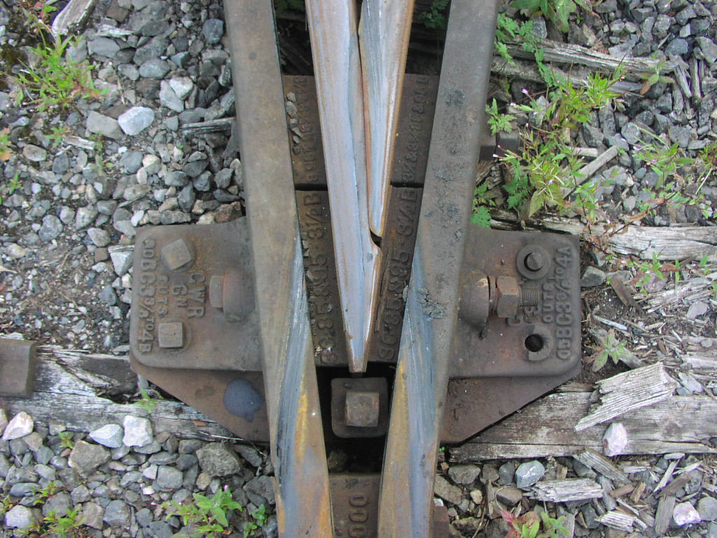
Martin Wynne wrote: David R wrote:HiDoesn't everybody?Hi David, Please note that the bolt at the nose on GW turnouts goes into the crossing timber. see attached photo. Cheers Phil PS. Not that there's much timber left on this nose |
||
| Attachment: attach_759_1074_P8110030.JPG 1656 | |||
|
posted: 17 Mar 2010 14:33 from: David R
click the date to link to this post click member name to view archived images |
Paul Boyd wrote: That crossing nose chair - I know C&L do one in brass but unless there's some odd colour rendering yours looks likes like resin. Is it? 100_170919_400000000.jpg C&L's A-chair casting is a GWR one without the triangular webs either side; this one is a NER design. All of the "white" bits in the photo are dozens of tiny bits of plastic card and rod. This is an O-fine crossing but if I can get my camera to focus close enough I'll see if I can post images of the EM gauge 3-way which I've done to the same detail, just to prove it could be done! Martin:Agreed, the crossing nose should be blunted but I was trying to reduce the gap at the expense of pushing the holding down bolt off of the timber (the foot of the point rail does actually extend beneath the plastic saddle, holding down bolt and washer). O-fine flangeways were reduced to 1.5mm (just possible with Slaters wheels) but the solution eventually decided upon was to change to S7 so all the track now needs changing. Hopefully I can reuse all my little bits of plastic... |
||
| Last edited on 21 Mar 2010 17:13 by David R |
|||
|
posted: 17 Mar 2010 15:04 from: Martin Wynne
click the date to link to this post click member name to view archived images |
David R wrote:O-fine flangeways were reduced to 1.5mm (just possible with Slater's wheels)Hi David, Very impressive to see scratch-built chairs. As you say, 1.5mm flangeways are border-line when used with 32mm track gauge, but 0-MF works fine with all wheels except at tinplate radii (31.5mm track gauge, 1.5mm flangeways). See: http://www.rmweb.co.uk/community/index.php/blog/253-heyside-7mm-scale-layout-br-late-50searly-60s/ regards, Martin. |
||
|
posted: 20 Mar 2010 19:34 from: David R
click the date to link to this post click member name to view archived images |
As promised a pic of an EM gauge "Vee" just to prove that the detail can be squeezed into a 1mm flangeway. At least the bits of plastic are a little bit bigger in S7 even if the flangeway is about the same size. 100_201354_510000000.jpg  This one is missing the triangular webs on the A-chair which it should really have as it's supposed to be part of a pair of NER 1:7 interlaced turnouts - I did try but the webs just wouldn't stay in place. Still hasn't got a blunt nose (sorry Martin) although the holding down bolt does appear to go through the timber this time. The purpose of this exercise was to see what was possible and what was practical. I think that I've prooved it's possible but at a huge cost in time. To make it practical in 4mm scale I'd use the Exactoscale components which weren't available when I started out. Apparently work on their S7 track components will start after ScaleForum North this year... Back to the OP's original question: build the "Vee" as a sub-assembly including the wing rails; pre-curve all the stock rails; get LOTS of track gauges and I do mean lots, you'll need at least a half-a-dozen for a single plain turnout, many more for complex assemblies, some will need "customising" to enable them to fit in certain locations; then temporarily hold ALL the bits together with the track gauges as you position the lot on the timbers. When happy with ALL the alignments stick it down (or solder it or whatever) one piece at a time, rechecking the alignments as you proceed. Dave R |
||
| Last edited on 21 Mar 2010 17:22 by David R |
|||
|
posted: 23 Mar 2010 22:58 from: Paul Boyd
click the date to link to this post click member name to view archived images |
Dave R wrote:get LOTS of track gauges and I do mean lots, you'll need at least a half-a-dozen for a single plain turnoutThank you! That, and Dave Bradwell's comments about the amount of gauge widening (or lack of) produced by 3-point gauges means I've just spent an evening making half a dozen roller gauges, three at +0.1mm and three at +0.25mm (working in P4). The trickiest bit was making a tool of just the right width to give a groove that snugly fits the rail head. I've got loads of straight 18.83mm gauges but was blindly relying on the 3-point gauges to produce widening without actually checking what they were doing! Tomorrow I'm going to rebuild half a turnout... |
||
|
posted: 23 Mar 2010 23:20 from: Martin Wynne
click the date to link to this post click member name to view archived images |
Paul Boyd wrote:I've just spent an evening making half a dozen roller gauges, three at +0.1mm and three at +0.25mm (working in P4).Hi Paul, Don't get them muddled up. I turn small grooves on them and fill with coloured paint. One groove for each 0.05mm widening while they are still in the lathe. regards, Martin. |
||
|
posted: 24 Mar 2010 12:41 from: Phil O
click the date to link to this post click member name to view archived images |
Martin Wynne wrote: Paul Boyd wrote:I've just spent an evening making half a dozen roller gauges, three at +0.1mm and three at +0.25mm (working in P4). Hi Martin It seems like identyfing resistors. Cheers Phil  |
||
|
posted: 24 Mar 2010 19:01 from: Paul Boyd
click the date to link to this post click member name to view archived images |
Hi MartinDon't get them muddled up.I took them into work and engraved 10 or 25 on one end! Coloured grooves are nice though, and being an electronics engineer I would have to colour the grooves brown, black and red, green respectively if I was going to use paint-filled grooves Maybe next time! |
||
|
posted: 24 Mar 2010 23:51 from: BruceNordstrand
click the date to link to this post click member name to view archived images |
Hey guys I read in a 1963 article of Model Railroader (by Jack Work) that notching one frog rail for the other to fit into it (staggered joint) was the way to go. I've never been able to figure that one out hence the need for me to file both sides the same. Is there any trick to doing a staggered joint or any advantage of doing so in HO scale? Cheers Bruce |
||
|
posted: 25 Mar 2010 13:52 from: Nigel Brown click the date to link to this post click member name to view archived images |
BruceNordstrand wrote: Hey guysI stagger the joint. At one time I used to rebate the splice rail into the point rail, but these days don't bother; I think the result is as good without, possibly better as you avoid the extra bit of filing. The advantage of a staggered joint is that the crossing tip is formed from one solid bit of rail, rather than two soldered together, which is likely to be a bit more fiddly to get right. I use a GW Models jig to file the rails to the required angle, which means it's fairly easy to get the angles right. cheers Nigel |
||
|
posted: 25 Mar 2010 14:29 from: BruceNordstrand
click the date to link to this post click member name to view archived images |
Thanks Nigel I reread Jack's article and while he doesn't notch the rail he does use one rail as the lead rail and the other butts up against it, the lead rail becoming the point. I suspect thats what you mean by a staggered joint. I tried to locate a website for GW Models but Google was next to useless but I suspect everything they have is no good for HO scale anyway. I'll think I'll just stick with the split rail method as I have a filing jig from Fasttracks plus I don't go to the detail level most of you guys do. I am actually seriously thinking about buying cast frogs from Proto87 stores.... Cheers Bruce |
||
|
posted: 25 Mar 2010 15:01 from: Nigel Brown click the date to link to this post click member name to view archived images |
Bruce The Fast Tracks jigs look fine, the GW Models ones are a similar idea except that the slot holding one rail continues to exit from the jig side so that if you stick a rail in the slot with the end extending out of the side, by filing parallel to the side its very easy to produce a rail end with the same angle as the frog angle (think Fast Tracks produce a separate jig for this). Like the Fast Tracks ones they are designed for specific rail, in my case 3mm Society code 60 bullhead rail. In my view the GW Model jig I use has one fault; the ends of the rail where they emerge from the jig to be soldered are too far apart, which means that the soldering takes place some way off the jig, which given the flexibility of the rail means that it's difficult to produce with certainty the angle of the frog one's looking for, which somewhat defeats the main purpose of the jig. The Fast Track ones look better in this respect. cheers Nigel |
||
|
posted: 26 Mar 2010 19:41 from: Dellboy
click the date to link to this post click member name to view archived images |
Hello again Having started this topic I thought I should at least let you know how I am getting on with my first venture into copperclad and to say for the points I have been installing the Vees first - followed by the stock rails because I then find it easier to set up the wing rails with these in place. First I built the fan to the storage sidings turntable, then I built the scissors crossover which sits at the base of the fan. For the scissors I started with one K-crossing, then the diamond Vees, wing rails from these back to the K-crossing followed by the second K-crossing and the other two wing rails. Once the diamond was completed the four remaining point Vees were fitted etc. Starting in the middle and working outwards like this made it quite easy to ensure correct alignments. I have used extended timbers to help hold everything in place and this has worked well providing considerable stability when handling. Will probably use this method for the more complex ply & rivet construction as the ply can be suitable trimmed back after installation. Also for the scissors I used a second copy of the templates for making up the various check rails etc. as I found it easier and more accurate to work off these rather than the main templates with the sleepers laid on top. The copperclad has come together very well so I am all for the Vee first approach. Finger 'rocket' propulsion of a four wheel wagon has failed to cause any rough riding. Full testing will come later. Pics show the fan & scissors layed roughly in position on the baseboard (note the extended timbers). Derek 1821_261438_450000000.jpg  1821_261439_500000000.jpg  |
||
|
posted: 15 Apr 2010 18:16 from: Templot User
click the date to link to this post click member name to view archived images |
Posted by email by Andrew Jukes ___________________________ Paul This is the thinking that led us to provide the following as part of the P4Track Co. range : 4XX TG01 P4 track gauges (Set of 4: 18.83mm, +0.1, +0.2, +0.3) These are not grooved as, if the rail is held upright (canted at 1 in 20) by functional chairs, you really only need to hold the gauge face of the rail against the gauge. If the gauge is grooved and fits the rail well, it may tend to hold the rail upright, resulting in undergauge track when the gauge is removed. Regards Andrew Jukes Exactoscale Ltd. |
||


| Please read this important note about copyright: Unless stated otherwise, all the files submitted to this web site are copyright and the property of the respective contributor. You are welcome to use them for your own personal non-commercial purposes, and in your messages on this web site. If you want to publish any of this material elsewhere or use it commercially, you must first obtain the owner's permission to do so. |