Templot Club Archive 2007-2020
|
|||
| author | remove search highlighting | ||
|---|---|---|---|
|
posted: 6 Mar 2011 10:39 from: sm
click the date to link to this post click member name to view archived images |
I'm trying to draw a single slip, I have even printed off the instructions from the "how to" site and have followed the instructions to the letter, although I have no clue what tcp or mcp means (training centre point/main centre point ?) My god could you make this any harder ?, two hours later and I still have no single slip. I have the diamond crossing and I've parked the switch heel template but then trying to get the thing to peg where I want it is a complete mystery. Why can't Templot just use a simple drag and drop user interface like any other windows based program?. If any one can offer some advice in simple English I'd be grateful |
||
|
posted: 6 Mar 2011 11:36 from: Martin Wynne
click the date to link to this post click member name to view archived images |
sm wrote: I have no clue what TCP or MCP meansHi Stuart, See the "gentle geometry" page in the Templot Companion at: http://www.templot.com/martweb/gs_geometry.htm#peg_positions from which: peg on FP -- Sets the fixing peg at the Fine-Point of a V-crossing (the rail gauge-face intersection point). Repeatedly selecting peg on FP (CTRL-4) toggles the peg alignment between the main road and the turnout road. The fine-point is a little way in front of the actual nose of the vee, which is blunted off to a width of 3/4" (scale) on bullhead track. 2_160721_340000000.png  red_pointer.gif  Do not confuse this Fine-Point at the gauge-face intersection with the term "frog point". This means the location of the blunt nose of the vee and is also sometimes abbreviated to FP, for example in North America (where the nose is usually blunted to 1/2" width). Do not confuse this Fine-Point at the gauge-face intersection with the term "frog point". This means the location of the blunt nose of the vee and is also sometimes abbreviated to FP, for example in North America (where the nose is usually blunted to 1/2" width).peg on TCP -- Sets the fixing peg at the Turnout-side Crossing Point. This position is on the turnout road centre-line in line with the FP fine-point. For a generic type of V-crossing, this position marks the end of the turnout radius, and is marked across between the rails. peg on MCP -- Sets the fixing peg at the Main-side Crossing Point. This position is on the main road centre-line in line with the FP fine-point. regards, Martin. |
||
|
posted: 6 Mar 2011 12:27 from: sm
click the date to link to this post click member name to view archived images |
Thanks Martin, I'm still none the wiser, why can't the Templot just have a slip template that can be dragged and dropped like the turnout templates? One thing I have noticed is that the instructions state... "click on the peg/align tools>align current template and snake onto peg>facing-trailing" but when clicking on the template and then on the peg/align tools, the option of "current template" is not there. There is the option to align the control template "over" etc. |
||
|
posted: 6 Mar 2011 12:39 from: sm
click the date to link to this post click member name to view archived images |
Also the instruction no:17 states "delete to current" but I don't have that option. I do have the option to delete or delete to the control but if I do that and then following instruction, no:18 the first part of the crossing dissappears? | ||
|
posted: 6 Mar 2011 13:18 from: sm
click the date to link to this post click member name to view archived images |
Also every time I add a template Templot labels it How do I switch this annoying feature off |
||
|
posted: 6 Mar 2011 13:19 from: Brian Nicholls
click the date to link to this post click member name to view archived images |
sm wrote: I'm trying to draw a single slip, I have even printed off the instructions from the "how to" site and have followed the instructions to the letter, although I have no clue what tcp or mcp means (training centre point/main centre point ?) My god could you make this any harder ?, two hours later and I still have no single slip. Hi Stuart, I generated a little noddy picture guide, last year, for my own reference, containing most of the peg positions that are listed in the drop down menu, see if it helps. I have put it into a PDF file for your to have a look, see attached file. However, all the information is in the Templot program, you just have to take the time to look. All the best, Brian Nicholls. |
||
| Attachment: attach_1002_1406_PEG_MENU_POSITIONS_ILLUSTRATED.pdf 562 | |||
|
posted: 6 Mar 2011 13:26 from: sm
click the date to link to this post click member name to view archived images |
Thanks Brian, I'm afraid I'm not very patient when it comes to using software. I bought a pcb design package last year which was soooo easy to use that within an hour I'd designed a circuit and was using it to make an etch. All I want from Templot is to be able to drag and drop templates into position, all the fancy aligning stuff should be done by the software in the background as I'm more interested in building track than I am sitting in front of a pc trying to design it. Even you've had to create an aide memoir to help you use Templot, it really shouldn't be this difficult. Anyway moan over thank you for your help and advice Rgds, Stuart |
||
|
posted: 6 Mar 2011 13:29 from: mike47j click the date to link to this post click member name to view archived images |
I found the best thing to do is to watch the making a slip video. Then watch the video again making a list of what to do. The try and do it refering to the list or if the notes are not clear then refer back to the video. Mike Johnson |
||
|
posted: 6 Mar 2011 13:45 from: Martin Wynne
click the date to link to this post click member name to view archived images |
sm wrote:I'm still none the wiser, why can't the Templot just have a slip template that can be dragged and dropped like the turnout templates?Hi Stuart, in a double slip there are 2 V-crossings, 2 K-crossings and 4 switches. All 8 of which have a multitude of variable settings. And then the whole lot needs to be curvable onto any radius or inserted wholly or partially in a transition zone. Not forgetting to allow for all the differences in prototype practice, UK and worldwide. And every model gauge from Z gauge to 5" gauge and larger, including all the narrow-gauge variants. You write the code and I will incorporate it into Templot.  Seriously, using partial templates is the only sensible option. It also matches prototype practice -- which is always our first point of reference, rather than a model track catalogue. If it's a straight slip and you don't want to create it yourself there must be a finished slip of the required gauge and angle in a downloadable file somewhere, which you can add as a group and then peg into position using the notch linking function. What gauge and angle are you looking for? Anyone help? If it's a curved slip the chances of finding one ready-made of the required gauge and angle curved onto the required radius must be very slim, so you don't have any choice but to create it yourself. It's really quite quick with a bit of practice. The "current" template is now called "the control template" or sometimes just "the control". It's only a change of wording, the actual functioning hasn't changed. Unfortunately it is impossible to develop the software, and simultaneously rewrite all the tutorials and remake all the videos. regards, Martin. |
||
|
posted: 6 Mar 2011 13:58 from: Paul Boyd
click the date to link to this post click member name to view archived images |
Martin wrote:If it's a straight slip and you don't want to create it yourself there must be a finished slip of the required gauge and angle in a downloadable file somewhere, which you can add as a group and then peg into position using the notch linking function. What gauge and angle are you looking for? Anyone help?I've done a few slips in the 9yrs 11months (not counting, honest!) since I've had Templot. Stuart - if, as Martin suggests, you let us know what track standard you're using and what crossing angle you need I'll see what I may have lurking, assuming it's a straight slip. You will then have to work out how to handle groups of templates. Brian - thanks for the PDF. I've been meaning to do something similar myself for some time! |
||
|
posted: 6 Mar 2011 14:11 from: sm
click the date to link to this post click member name to view archived images |
Thanks Paul, I must be really thick because I can't even see how to attach a file to this post to show you what I'm trying to achieve. If you can imagine a sissor crossing but instead of the righthand side being turnouts they are instead single slips. So two roads diverge into four, I'd attach diagram but it would seem that even that is beyond me, The gauge is 2mm. I can do all the simple things within Templot but this slip building is just far to complexed, it's a shame Martin that you don't do a lite version for those of us who would be quite happy with simple track plans to drag and drop into place. Anyway I've just spent 5hrs at this thing and the pc is in danger of going out the window soon , so I'm going to go do something differnt for a while. Thanks for the advice, Stuart |
||
|
posted: 6 Mar 2011 14:41 from: Paul Boyd
click the date to link to this post click member name to view archived images |
Hi Stuart Do you mean something like the attached screen shot? I've assumed you mean 2mm scale (not N) rather than gauge. This is a very quick hash just to check the idea. I've used 1 in 6 crossings but I think it would be better as 1 in 8. To attach a file to a post, you simply browse to it in the box below and click on the file. Templot isn't intended to be about quickly knocking up track plans - it's to aid in the construction of prototypical track formations. This is why it has an bewildering array of options. One person might be modelling contemporary British railways, another might be modelling 1920 GWR, I model 1960s Festiniog Railway in S4n2, people are modelling early Bavarian railways, all of these things have different requirements so it would be impossible to just drop in a "standard" single slip because there's no such thing. That's even before you get into whether it's straight or one or both through roads are curved. One of my layouts has a three-way stub point - I'm sure Martin had no idea that anyone would want to build one of those with Templot! Cheers |
||
| Attachment: attach_1003_1406_Scissor-slip.png 1216 | |||
|
posted: 6 Mar 2011 14:51 from: sm
click the date to link to this post click member name to view archived images |
Hi Paul, Yes 2mm not ngauge That is almost exactly what I am trying to achieve except the slip roads are on the other sides. 1:6 is what I was working to, to save space. Your skill and patience far exceeds mine. Rgds, Stuart |
||
|
posted: 6 Mar 2011 14:58 from: Paul Boyd
click the date to link to this post click member name to view archived images |
OK - watch this space! (Give me a day or so) | ||
|
posted: 6 Mar 2011 15:01 from: sm
click the date to link to this post click member name to view archived images |
That is really kind Paul Thank you Stuart |
||
|
posted: 6 Mar 2011 19:57 from: Martin Wynne
click the date to link to this post click member name to view archived images |
sm wrote: Also every time I add a template, Templot labels it. How do I switch this annoying feature offHi Stuart, Press the END key on the keyboard, or click the pad > hide name labels menu item: 2_061450_500000000.png  However, if you are creating a slip you need the labels showing. By SHIFT+clicking on the name label you can select a specific template when you have several partial templates superimposed. To show the name labels again, press the END key again. regards, Martin. |
||
|
posted: 7 Mar 2011 19:02 from: Paul Boyd
click the date to link to this post click member name to view archived images |
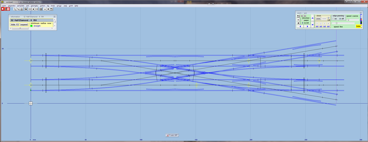
Stuart - a quick question. What minimum radius are you working to? Doing this as 1in6 is a bit tight and I've used various tricks to get up to 17.5" radius. The equivalent in P4 would normally be considered too tight! (Edit - up to 17.5" minimum radius now!) |
||
| Last edited on 7 Mar 2011 19:08 by Paul Boyd |
|||
|
posted: 7 Mar 2011 20:45 from: sm
click the date to link to this post click member name to view archived images |
Hi Paul, I'm afraid you've got me there, the design is for a station throat with the divergeing lines coming off the main lines and running into the station platforms. I'm trying to squeeze the whole layout into an 8' length hence the tight radius's. Oridginally I made a templot design as per but because I can't create slips yet I just made the exits from the turnouts with lengths of straight track that crossed over the other section of straight track and it all fitted the space available. but if you think this is going to be too tight I will defer to your experience. This is very kind of you to do but please don't waste to much of your time on this unless you really want to or like the challenge. I hope that helps Rgds, Stuart. ps: I'm away from my pc for the next few days so replys might take a little longer |
||
|
posted: 7 Mar 2011 21:06 from: Paul Boyd
click the date to link to this post click member name to view archived images |
I enjoy the challenge... The tightest radius is on the entry turnouts, at 17.5". This should be OK for most applications, although you may not want to get a 9F through it! To use this formation, you'll need to import it to your current plan as a library (Storage box => Add library), and also read up about handling grouped templates - you'll need to group all of these so that the whole formation can be moved as one. I've left the peg at the Ctrl-0 point on each of the entry turnouts which should help with alignment. Anyway, that kept me quiet for a couple of hours or so! |
||
| Attachment: attach_1005_1406_2mm_scissorslip_11_03_07_2100_33.box 336 | |||
|
posted: 8 Mar 2011 20:53 from: sm
click the date to link to this post click member name to view archived images |
Thanks Paul, I'm away from my home pc at the moment but get back to morrow so I'll download and have look then Rgds, Stuart |
||
|
posted: 8 Mar 2011 20:55 from: sm
click the date to link to this post click member name to view archived images |
ps The layout will be circa 1970-75 so just corporate blue diesels and dmus | ||
|
posted: 9 Mar 2011 13:01 from: adj click the date to link to this post click member name to view archived images |
Brian Nicholls wrote:
Brian, you're a star, that PDF is just what I've needed! Adriano |
||
|
posted: 9 Mar 2011 13:29 from: sm
click the date to link to this post click member name to view archived images |
Thanks Paul, That's perfect All I have to do now is build it Once again many many thanks Rgds, Stuart |
||
|
posted: 10 Mar 2011 17:38 from: Paul Boyd
click the date to link to this post click member name to view archived images |
That formation should be an interesting build - I'd love to see some photos when you get that far. Paul |
||
|
posted: 10 Mar 2011 17:43 from: sm
click the date to link to this post click member name to view archived images |
will do | ||
|
posted: 11 Mar 2011 08:57 from: Alan Turner
click the date to link to this post click member name to view archived images |
sm wrote: All I want from Templot is to be able to drag and drop templates into position, That isn't how TEMPLOT works. You can "drag and drop" templates but you will never get the geometry correct doing it. You have to establish your geometry first and then insert the turnouts into it. Alan |
||
|
posted: 13 Mar 2011 16:14 from: Jonathan Wells click the date to link to this post click member name to view archived images |
Brian Nicholls wrote: Thank you, Brian for that useful PDF, I've downloaded and printed it out.  |
||
|
posted: 17 Mar 2011 16:19 from: sm
click the date to link to this post click member name to view archived images |
Hi Paul, I've made a start which can be viewed here Paul Boyd wrote: That formation should be an interesting build - I'd love to see some photos when you get that far. |
||
|
posted: 17 Mar 2011 16:40 from: Stephen Freeman
click the date to link to this post click member name to view archived images |
Paul Boyd wrote: That formation should be an interesting build - I'd love to see some photos when you get that far.Ahem. For something not entirely dissimilar in 0FS have a look to your left. Better pic on website |
||
| Last edited on 17 Mar 2011 16:41 by Stephen Freeman |
|||
|
posted: 18 Mar 2011 18:47 from: Paul Boyd
click the date to link to this post click member name to view archived images |
Hi StuartI've made a start which can be viewed hereWhere?  |
||
|
posted: 18 Mar 2011 19:27 from: sm
click the date to link to this post click member name to view archived images |
http://www.stuartmoore-modelrailways.co.uk/2mm_fine_scale.htm | ||
|
posted: 18 Mar 2011 22:05 from: Rob Manchester
click the date to link to this post click member name to view archived images |
Hi Stuart, Yes, your work looks good. Where do you get the special gauge for checking the flatness of the crossing work ? There may be a market for them. I often look at some of the N gauge RTR stock and think a layout may be just around the corner. The BR Mk 1 coaches look brilliant. The finescale 2mm track systems look very nice and some of the jigs and fittings make modellers in other scales look poorly served. The only downside seems to be that some of the RTR locos still look poor and it only seems to be the very new releases that are up to the mark. Good luck with the rest of the track. Rob |
||
|
posted: 18 Mar 2011 22:16 from: sm
click the date to link to this post click member name to view archived images |
Hi Rob, Re gauge for flatness of crossing, I just use the edge of a steel rule. You can't go wrong with an ngauge or 2mm layout, a train of 7 carrages and 1 loco fits into 4' or perhaps a shunting plank or diorama, go on you know you want to really. Your right the latest rtr stuff is excellent, personally I prefer to model than count rivits so I'm not that fussed about uber detail in 2mm which you can't see from 12" away anyway except through the lens of a camera. Thanks for your words of support Rgds, Stuart Rob Manchester wrote: Hi Stuart, |
||
|
posted: 18 Mar 2011 22:58 from: Paul Boyd
click the date to link to this post click member name to view archived images |
Hi Stuart - that looks good! I see you noticed that some of my timbering wasn't quite right! I also spotted your modifications to the check rail around the diamond. As well as P4, I model S4n2 which is 4mm scale, nominal 2ft gauge using the 2mm Scale Association track standards with the gauge reduced to 7.83mm, so I know what it's like to build trackwork to those standards. I like your use of brass wire as guides - I tend to use 20thou brass strip for the same purpose. Most people who are new to track building start with a simple turnout Keep the photos coming. |
||
|
posted: 10 Apr 2011 13:33 from: sm
click the date to link to this post click member name to view archived images |
Hi Paul, Trackwork all completed, now for the electrics http://www.stuartmoore-modelrailways.co.uk/2mm_fine_scale.htm Rgds, Stuart Paul Boyd wrote: Hi Stuart |
||
|
posted: 10 Apr 2011 15:05 from: Paul Boyd
click the date to link to this post click member name to view archived images |
Hi Stuart Not only is the trackwork impressive, so is the speed of construction! I have noticed some check-rails missing though. These are the four check-rails for the diamond crossing Vees - on the first photo on your link you can see that they are shown on the template but have never been fitted. Sorry |
||
|
posted: 10 Apr 2011 19:06 from: sm
click the date to link to this post click member name to view archived images |
Hi Paul, I welcome constructive criticism, and your right I have left off 4 check rails, firstly by mistake but by the time I noticed they were missing the truck ran across the crossing ok I thought I'd just leave them off otherwise it would all get a bit to busy but I might look again. Thanks for the Templot plan without which I couldn't have made the turnout Rgds, Stuart Paul Boyd wrote: Hi Stuart |
||
|
posted: 10 Apr 2011 22:35 from: Jim Guthrie
click the date to link to this post click member name to view archived images |
sm wrote: Hi Paul,Stuart, It's when you try something like propelling several four wheel wagons through the formation that you might find the need for the check rails. Jim. |
||
|
posted: 18 Aug 2011 20:31 from: sm
click the date to link to this post click member name to view archived images |
Paul Boyd wrote:That formation should be an interesting build - I'd love to see some photos when you get that far.Hi Paul, Long time no update but if you're interested in seeing what has become of the sissorslip follow this link . I have another idea for which I might need your skills again if you're interested. Rgds, Stuart |
||
|
posted: 11 Sep 2011 23:09 from: Richard_Jones
click the date to link to this post click member name to view archived images |
Hi Guys (& Gals) There's no doubt that slips, both single and double are complex formations - I have left this till the last to tackle for my projected layout, and have now come up with something that is approaching what I need (that is a 1:8 double slip on a 15' radius) by following the video I'm not convinced I have got it right but here's my attempt.... Comments etc please, Ladies and Gentlemen.... Any thoughts as to whether it will work in EM? best wishes Richard |
||
| Attachment: attach_1176_1406_Singleton_Double_slip.box 279 | |||
|
posted: 12 Sep 2011 11:37 from: JFS
click the date to link to this post click member name to view archived images |
Hello Richard, I would have thought should work - 15' is quite generous - but then I have never built in EM! It might be a Good Thing to build this first to test it out - it may need to have moving elbows instead of fixed ones if flanges tend to wander the wrong side. Just to note that, as it is currently drawn, your part-finished switches start behind the check rails. It might be a good idea to substitute a "proper" set of switches to make sure they fit. Best Wishes, Howard |
||
|
posted: 12 Sep 2011 12:03 from: Alan McMillan
click the date to link to this post click member name to view archived images |
Hi Richard I've rejigged your slip a bit. Now the check rails no longer foul the blade ends and the upper slip road isn't straight with the kink in it at the switch heels. Regards Alan |
||
| Attachment: attach_1177_1406_Singleton_DS_Redrawn.box 223 | |||
|
posted: 12 Sep 2011 13:23 from: Richard_Jones
click the date to link to this post click member name to view archived images |
Howard, Many thanks for the comments & Alan Many thanks for the corrections. I'm currently at work (lunchtime - honest!) so can't try the revised template till this evening (if I'm allowed...) Richard ps. I should know this, but.... how do you import a template into an existing box file? Presumably with an assembly of several Templates you can group select and manouver it as a whole?  |
||
|
posted: 13 Sep 2011 08:35 from: Richard_Jones
click the date to link to this post click member name to view archived images |
OK, Found how to import the modified slip into the overall layout BOX file.... Still not certain how to accurately drop the group into the space where originally I had the "interim" crossing.... Also - can anyone remind me how to/ is it possible to include the shape file when printing out at reduced scale - I keep ticking options but don't get the shape included... Trying to get a small print to start baseboard planning.. By the way, the avatar is a small section of the 1880(?) OS map for the Singleton area (at the time the line was being built) many thanks for any help - I'm sure I should know the answers to my own questions, if only I was more familiar with the software.. best wishes Richard |
||
|
posted: 13 Sep 2011 09:49 from: Martin Wynne
click the date to link to this post click member name to view archived images |
Richard_Jones wrote: Still not certain how to accurately drop the group into the space where originally I had the "interim" crossing....Hi Richard, There is a bit of Jing video here which may help: message 3980 Also - can anyone remind me how to/ is it possible to include the shape file when printing out at reduced scale - I keep ticking options but don't get the shape included...You mean the scanned image in a picture shape? Like this: background_print.jpg  On the print pages dialog click the picture shapes tab and then the print pictures (stretch) option: print_picture_shapes.png  Make sure you click the ? help button and read the notes. And check your ink cartridges! (N.B. If still using Windows 95, 98 or ME this is unlikely to be successful if you are printing finished templates. In most cases the degree of magnification required is too great. This is a Windows restriction, not Templot. It might work at lower magnifications, for example when printing an entire track plan using "fit single page". It might also work if you change the printer to a lower print quality/resolution.) regards, Martin. |
||
|
posted: 13 Sep 2011 12:58 from: Richard_Jones
click the date to link to this post click member name to view archived images |
Martin Many thanks..... I really should read the instructions more thoroughly I am currently printing out at 10% to help me with designing the baseboards - an interesting article in the current edition of MRJ (209) on this topic. Perhaps if I were designing layouts more frequently I would become as familiar with the software as we are with our word processing, spreadsheet and presentation packages that are "dumped" on us at work, where they expect you just to "get on with it" best wishes Richard: |
||
|
posted: 14 Sep 2011 01:46 from: Richard_Jones
click the date to link to this post click member name to view archived images |
Hi Martin all worked perfectly.... now to think about building? cheers Richard |
||


| Please read this important note about copyright: Unless stated otherwise, all the files submitted to this web site are copyright and the property of the respective contributor. You are welcome to use them for your own personal non-commercial purposes, and in your messages on this web site. If you want to publish any of this material elsewhere or use it commercially, you must first obtain the owner's permission to do so. |