Templot Club Archive 2007-2020
|
|||
| author | remove search highlighting | ||
|---|---|---|---|
|
posted: 22 Oct 2014 18:39 from: Julian Gascoyne click the date to link to this post click member name to view archived images |
Hi all I wonder if anyone more experienced than me in railway track matters would be kind enough to comment on the attached track formation? In the 'in progress' plan I have two versions of the station throat. One version contains a curved formation of scissors cross over with a double slip on one leg. The second version (just below the first in green) has a straight formation of scissors cross over with double slip. So which to choose? The straight formation will be easier to build. But the double slip has ended up with a 1:6 slip road on one side to avoid the diamond crossing V. And I'm not sure about the 1:8 slip road on the other side passing under the check rail. Also I much prefer the look of the curved formation, it makes better use of the space too. But the double slip has ended up as an irregular diamond (V10, K8, K8.02, V6.87), is that feasible / workable? Would anyone care to comment on these two scissors crossover and double slip formations? Are they buildable, workable? Are there any school boy errors that need correcting? (p.s. ignore the timbers, I haven't got that far yet.) Many thanks Julian |
||
| Attachment: attach_1979_2555_MR_terminus_curved_points_v2.box 386 | |||
|
posted: 23 Oct 2014 19:00 from: Paul Boyd
click the date to link to this post click member name to view archived images |
Hi Julian 28 downloads and no comments! I would agree that the curved formation looks better, and they're no harder to build than a straight one. The main thing that bothers me is that a train travelling left to right on the top line, and exiting left on the double slip, has an abrupt change of curvature to cope with as it joins the slip road. I think you might have problems there. If the scissors curved in the other direction you would get away with it, but that's obviously not going to work here! Based on that, I would go with the straight version. Otherwise, I think it looks OK, although I'm also not sure about the slip road and the check rail thing on the straight version - I'm not sure you'll get away with that. Cheers |
||
|
posted: 24 Oct 2014 17:53 from: Tony W
click the date to link to this post click member name to view archived images |
Hi Julian. I am one of those who has download your track plan with the intention of having a detailed look at it, but it was close to midnight and domestic matters have prevented me from having more than a quick look so far. I will come back to you with my comments in due course. Regards Tony. |
||
|
posted: 24 Oct 2014 18:37 from: Julian Gascoyne click the date to link to this post click member name to view archived images |
Paul Boyd wroteThe main thing that bothers me is that a train travelling left to right on the top line, and exiting left on the double slip, has an abrupt change of curvature to cope with as it joins the slip road. I think you might have problems there.Paul Thanks for taking a look. I think you have a very good point about the reverse curve, hadn't thought of that. There is another reverse curve at the start of the bottom left turnout on the scissors crossover as well. Neither is ideal especially when pushing bogie coaches into the platform. Actually a curved double slip is bound to have a reverse curve on the outside slip, maybe that is a good reason to keep the formation straight. I do have a hankering to go for a flowing curve though so maybe I'll have another go. I wonder how the real thing would lay it out? Julian |
||
|
posted: 24 Oct 2014 23:05 from: Tony W
click the date to link to this post click member name to view archived images |
Hi Julian. I have now had a better look at your track plan and I am afraid there are several issues that need looking at. Although your design of curved scissors and double slip will work and you have correctly used straight cut switches for your turnouts. You have used the standard track centres of 44.67mm to generate all your parallel tracks. This is alright for straight track and curves down to about 8800mm radius, but for sharper curves increased track centres are required. This is a common error. To allow for vehicle end and centre throw between templates 11 and 12 they should be at 53mm centres for 1067mm radius and between templates 28, 30 and 40 they should be at 49mm centres for 2085mm radius. This can be adjusted using the Adjacent track centres option under the Geometry drop down menu before generating double track, crossovers etc. Altering these will affect the design of the scissors crossover and give more room for the slip roads at that end. Your Tandem turnout in the platform will not work as it stands as the switch blades of the second turnout are much to close to the first and do not have enough room to open fully. You have made a good start and it is better to find out now than later, so well done for asking for guidance before getting too far with it. If you need further help, please ask. Regards Tony. |
||
|
posted: 25 Oct 2014 21:24 from: Julian Gascoyne click the date to link to this post click member name to view archived images |
Tony W wrote: Hi Julian.Thank you for pointing out this error - something I would not have realised. I think it best if I have a go at redesigning the fomation but removing the reverse curve on the double slip and setting the correct track centres as you have outlined. Hopefully I will post this tomorrow. Many thanks for your advice Julian |
||
|
posted: 26 Oct 2014 15:01 from: Julian Gascoyne click the date to link to this post click member name to view archived images |
Latest go at planning the station throat attached. I'm still keen to keep the curved formation. I have removed the double slip to avoid the reverse curve pointed about by Paul. So now the main roads sweep into the platforms on a continuous curve. There is still a reverse curve on the entry to the van sidings though. Not sure if that will cause problems? I've also reworked the parallel roads to increase the track centres as suggested by Tony. Out of interest, how did you arrive at 53mm centres for 1067mm radius and 49mm centres for 2085mm radius? Is that by experiment or is there some formula or rule of thumb you use to calculate the track centres required? Julian |
||
| Attachment: attach_1984_2555_MR_terminus_curved_points_v4.box 331 | |||
|
posted: 26 Oct 2014 23:22 from: Tony W
click the date to link to this post click member name to view archived images |
Hi Julian. The track spacing dimensions come from a versine formula from which I constructed a spreadsheet and produced the following table which was posted back in 2012 in a similar thread. 2151_201728_420000000.png 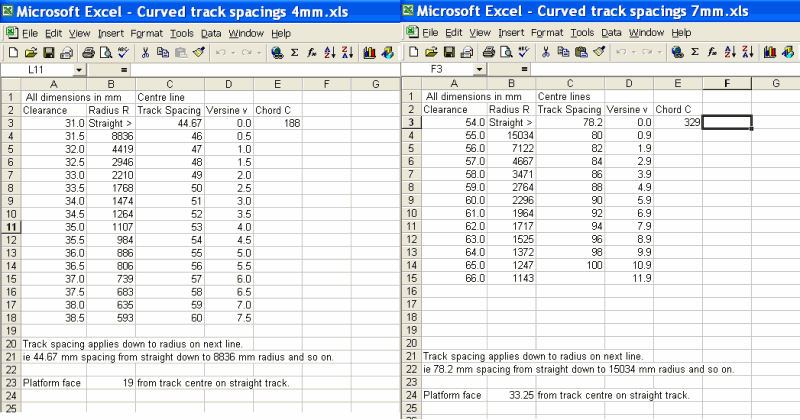 I will have a look at your latest box file. Regards Tony. |
||
|
posted: 27 Oct 2014 20:40 from: Julian Gascoyne click the date to link to this post click member name to view archived images |
Tony That is excellent - really useful information. Thanks Julian |
||
|
posted: 27 Oct 2014 21:12 from: Julian Gascoyne click the date to link to this post click member name to view archived images |
Tony W wrote: I will have a look at your latest box file.Tony I've just realised there is a mistake in the scissors crossover - by increasing the track centres the V crossings have now moved to a position where they 'line up' with the diamond V crossings so cannot be checked correctly. Let me have another go before you spend your time taking a look. People say Templot is a hard program to use, I don't agree. I have no problem using Templot. The hard bit is being your own track engineer and designing workable formations, its like solving a 3-D puzzle! Strangely addictive though. Julian |
||
|
posted: 28 Oct 2014 01:10 from: Tony W
click the date to link to this post click member name to view archived images |
Hi Julian. I had a quick look last night and the general layout appears much better. I will let you have another go but offer a little tip. By making small adjustments to the track spacing, (and I mean fractions of a mm) you can alter the way the timbers line up with those on the next track when generating a crossover. Say for instance the crossing timbers are 1mm out of line with each other for a 1 in 8 crossover altering the track centres by 1/16th of a mm in the appropriate direction should bring them into line because both turnouts of the crossover will be moved along its length by the required displacement divided by the crossing angle. This may help you to align both sets of timbers in the crossovers in the scissors. Regards Tony. |
||
|
posted: 28 Oct 2014 05:52 from: Tony W
click the date to link to this post click member name to view archived images |
Hi Julian. You might have to try something like this but curved. Tony. |
||
| Attachment: attach_1985_2555_Scissors.box 304 | |||
|
posted: 1 Nov 2014 12:24 from: Julian Gascoyne click the date to link to this post click member name to view archived images |
Latest version, this time trying to get the curved scissors crossover with the V-s in a place where they don't conflict. I have ended up using short check rails with machined flares to provide clearance for the running rails. Will these check the V-s properly? Also I've had a go at the central V on the tandem turnout. I think I've got it right? Any feedback welcome. Thanks Julian |
||
| Attachment: attach_1989_2555_MR_terminus_curved_points_v6.box 318 | |||
|
posted: 1 Nov 2014 14:35 from: Phil O
click the date to link to this post click member name to view archived images |
Hi Julian It doesn't look like it, as the flare ends past the tip of the "V" The flare should end before the knuckle to be of any use at least on the bottom left check which is the only one I have studied. Phil |
||
|
posted: 1 Nov 2014 15:09 from: Martin Wynne
click the date to link to this post click member name to view archived images |
Julian Gascoyne wrote:I have ended up using short check rails with machined flares to provide clearance for the running rails. Will these check the V-s properly?Hi Julian, The wheels must be under full control of the check rail before they reach the knuckle gap in the V-crossing, i.e. they must be on the working part of the check rail beyond the flared end. Otherwise the wheels could move a fraction sideways in the gap, leading to rough running, and they may even strike the nose of the vee. Unfortunately some of your crossings are not properly checked (yellow arrows): 2_010945_560000000.png 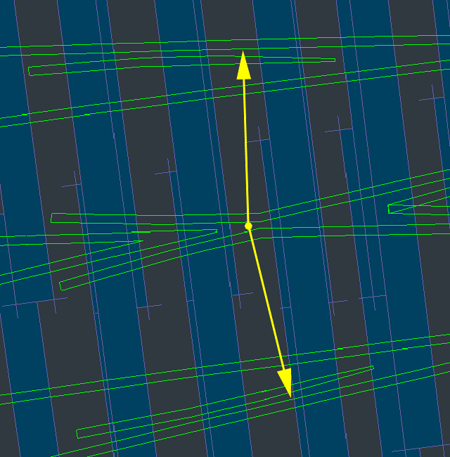 Here I am shortening the length of the flared part to make sure the V-crossing is properly checked. This flare length mouse action does not affect the overall length of the check rail. Each end of a check rail is adjusted separately by clicking the label (in this case DS1): 2_010948_320000000.png 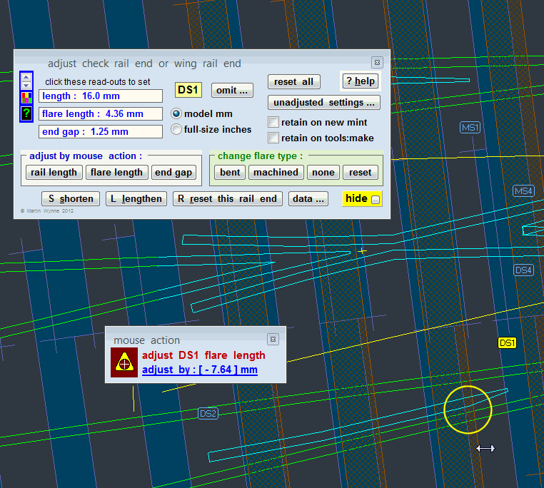 This is at real > adjust check rails... menu item. regards, Martin. |
||
|
posted: 2 Nov 2014 12:49 from: Julian Gascoyne click the date to link to this post click member name to view archived images |
Martin Wynne wrote:The wheels must be under full control of the check rail before they reach the knuckle gap in the V-crossing, i.e. they must be on the working part of the check rail beyond the flared end.Phil & Martin Thank you both for the advice. I now understand what the 'checking' is trying to achieve, a bit of a lightbulb moment! Julian |
||
|
posted: 3 Nov 2014 23:26 from: Tony W
click the date to link to this post click member name to view archived images |
Hi Julian. I have had a look at your latest box file. Your tandem looks OK to me, so now the timbering just needs sorting out. With the scissors, I have gone through the templates one by one and grouped them all together at the highest numbers and removed the duplicate timbering so only one layer of each turnout has the timbers visible. You will find this a great help when you start timber shoving as you won't have duplicate multiple layers to confuse you. In order to create the short check rails for the diamond, you will need to generate just a crossing nose (I put the peg at Ctrl 4) and move (F7) and rotate it (F8) to mirror the running one. (Unless there is a better method that I don't know about). Adjust the curvature to match the running rail (F6). The crossing angle usually needs to be altered slightly too (F5). Then adjust the check rails length (set flare to none) to match up to it, then shorten the new crossing nose to match the end of the check rail. I have done both of the right hand ones so you can see what needs doing but left those at the other end for you to try and see how you get on. Box file attached. Regards Tony. |
||
| Attachment: attach_1991_2555_MR_terminus_curved_points_v6a.box 282 | |||
|
posted: 4 Nov 2014 11:58 from: Martin Wynne
click the date to link to this post click member name to view archived images |
Tony W wrote:In order to create the short check rails for the diamond, you will need to generate just a crossing noseHi Tony, In Templot2 there is seldom a need to use a vee nose partial template as a check rail flare, as you have done at A (unless you know of some prototype reason for this?): 2_040637_450000000.png 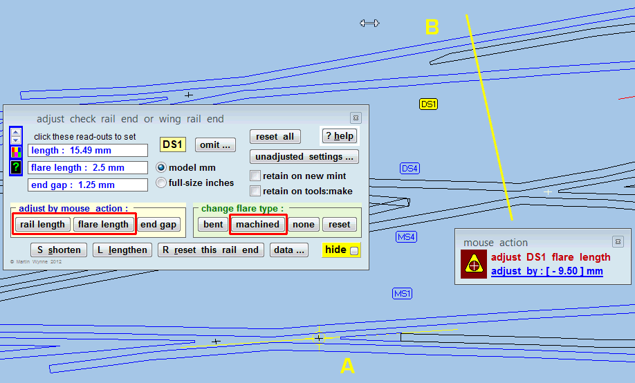 At B you can see that there is plenty of room clear of the knuckle (yellow line) to have a short machined flare on the DS1 check rail end. Here I am shortening the flare length by mouse action after shortening the rail length. Here is a pic from the Scalefour web site showing such a short machined flare on a wing rail: chairs04.jpg 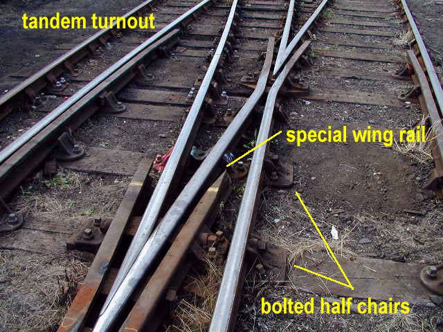 from: http://www.scalefour.org/resources/trackdetails.html#row06 The crossing angle usually needs to be altered slightly too (F5).When adjusting the crossing angle on a partial template it is usually better in Templot2 to use F9 rather than F5. The default option on F9 is for infinite angle adjustment (instead of unit-angle stepping), and F9 doesn't change the size of the blanked-off switch. With the F5 size mouse action Templot changes the switch size to match the crossing angle, which can produce some unexpected changes to the template length when working with a partial template (if you forget to lock the switch first regards, Martin. |
||
|
posted: 4 Nov 2014 18:05 from: Tony W
click the date to link to this post click member name to view archived images |
Hundefined Interesting picture, can't say I have seen it done quite like that before, the usual arrangement I have seen if there is insufficient room for a flared end is as shown in the picture below. I know it is of an industrial scissors, but the same principles apply to main line track. 2151_041252_290000000.jpg 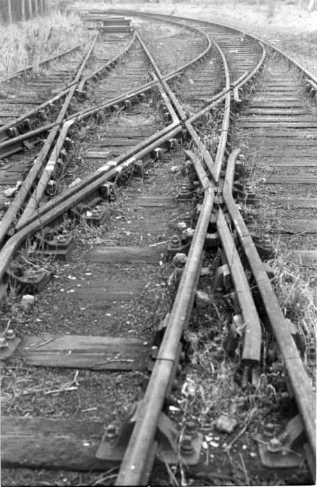 Interesting chairing arrangement. I take your point about using F9 rather than F5 and have experienced the sudden change in length when the switch type changes because I have forgotten to lock it. Regards Tony. |
||
|
posted: 4 Nov 2014 19:13 from: Martin Wynne
click the date to link to this post click member name to view archived images |
Hi Tony, Hmm. That does look a bit industrial without any flare on the checking face. Likewise the use of a normal spliced vee on the ends of the K-crossing check rails also does not provide any check flare. Here is a scan from David Smith's excellent GWSG track book*. I hope this small section of the drawing falls within fair dealing for copyright: 2_041355_420000000.jpg 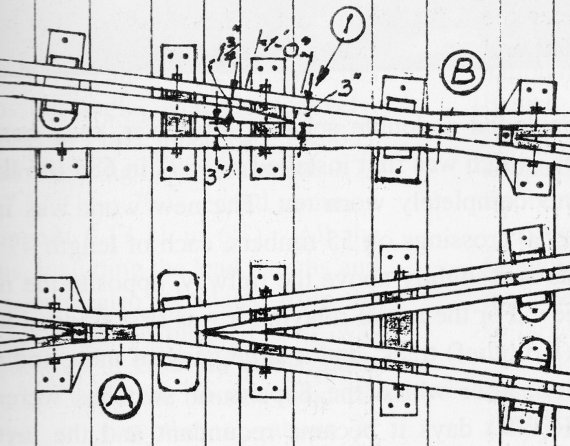 Note 1 says "end of shortened guard/check rail 3" clear of running faces, with 1ft-0in flare on checking face" which is more in line with the pic on the Scalefour page. Similarly the ends of the K-crossing check rails are machined to fit together with a flare on the checking face, rather than spliced as a normal vee. Note the easy knuckle bend radius at A, unlike the sharp bend which some modellers prefer -- even going to the extent of putting a nick in the rail to achieve it. *from: http://gwsg.org.uk/GWSG_Publications.html regards, Martin. |
||
|
posted: 5 Nov 2014 00:24 from: Julian Gascoyne click the date to link to this post click member name to view archived images |
Tony & Martin Thanks for taking the time to comment, interesting discussion and pictures. I think I'll stick with the machined flare rather then the V-nose for the diamond check rails. Having spent a happy evening shoving timbers, I think the track plan for the terminus is complete? Box file attached. Julian |
||
| Attachment: attach_1993_2555_MR_terminus_curved_points_v8.box 211 | |||
|
posted: 5 Nov 2014 23:05 from: Tony W
click the date to link to this post click member name to view archived images |
Hi Martin. Interesting and informative drawing. I sometimes wonder just how many variations there were between different companies practices, they must be legion. I must admit to sometimes filing a bit of a flare to the end of a model check rail where things looked a bit tight, but was never sure if it was prototypical or not. Your comment about the bend radius at A in the rails in an obtuse crossing is equally valid for common crossings at B. The prototype Crossing Flangeway gap is fixed at 1 3/4 inches, but the gap at the crossing throat can vary depending on the angle but for Flat Bottom track is specified as 2 inches for any crossing angle of 1 in 5 or greater for both common and obtuse crossings. Cast iron spacer blocks ensure that this is so. I would expect it to be similar for Bull head track, but do not have the figures. It is a common mistake to make these a sharp bend and one that I was guilty of until I learned better. I still have some turnouts where the wheels occasionally click as they negotiate the crossing as a result of my ignorance. I now test the throat gap with the Crossing Flangeway gauge and ensure it is a very loose fit. If it is tight then I know there is a problem to resolve. I had better close now before this thread wanders even further off track. Regards Tony. |
||
|
posted: 6 Nov 2014 00:11 from: Martin Wynne
click the date to link to this post click member name to view archived images |
Tony W wrote:I would expect it to be similar for Bull head track, but do not have the figures.Hi Tony, The knuckle gaps for bullhead (in mm) are in the 2nd table on this page, although I think the data contains some typos: http://templot.com/companion/prototype_information.php I had better close now before this thread wanders even further off track.It will be an odd topic which doesn't. regards, Martin. |
||
|
posted: 6 Nov 2014 00:12 from: Tony W
click the date to link to this post click member name to view archived images |
Hi Julian. First of all I would like to congratulate you on a job well done. There are a couple of very minor things to comment on. You did not quite get the timbering right on the exit track of turnouts 59 and 22 using your numbers otherwise you have produced a very workable solution. We now get into one of the subtleties of Templot. In your Scissors crossover and Tandem turnout, you have lost some of the end of switch blade markers. These are dependent on the order in which the background templates are stored in the storage box and the Stock rails that carry them need to be on top i.e. a higher number in the sequence, than the background templates that have the sleepers visible. I have done the Scissors crossover for you and if you compare the both versions, you will see what I have done. The Tandem is however a bit more of a challenge as the required rails are hidden altogether. I will have a go at it for you so that can see what it should look like, but there is nothing to stop you now from discovering the joys of printing your track plan. Use the output menu for the most accurate printouts and calibrate your printer with the calibrate option at the bottom then use the Print background templates option. Print-now! uses the printer uncalibrated and most printers have some error factor which can add up over a distance. Regards Tony. |
||
| Attachment: attach_1994_2555_MR_terminus_curved_points_v8a.box 225 | |||
|
posted: 6 Nov 2014 00:24 from: Tony W
click the date to link to this post click member name to view archived images |
Martin Wynne wrote: Tony W wrote:I would expect it to be similar for Bull head track, but do not have the figures.Hi Tony, Hi Martin. I had forgotten about those pages myself. I knew I had seen it somewhere. There is a great deal of useful prototype info in that section. Regards Tony. |
||
|
posted: 10 Nov 2014 14:14 from: David R
click the date to link to this post click member name to view archived images |
And curved flares for check rails as well please! Dave R |
||
|
posted: 11 Nov 2014 21:02 from: Julian Gascoyne click the date to link to this post click member name to view archived images |
Tony W wrote: There are a couple of very minor things to comment on......Tony I only noticed your post today, not sure how I missed it! Thanks for the comments about the timbers and also about the importance of the order of the templates in the box, that would have caused me much head scratching I think. I am contemplating building a 'model of the model' as it were, to see if I am happy with how it looks, so my next step is to have a go at printing the templates at probably 1/4 size. Many thanks again for your help. Julian |
||
| Please read this important note about copyright: Unless stated otherwise, all the files submitted to this web site are copyright and the property of the respective contributor. You are welcome to use them for your own personal non-commercial purposes, and in your messages on this web site. If you want to publish any of this material elsewhere or use it commercially, you must first obtain the owner's permission to do so. |