Templot Club Archive 2007-2020
|
|||
| author | remove search highlighting | ||
|---|---|---|---|
|
posted: 3 Apr 2015 20:10 from: madscientist click the date to link to this post click member name to view archived images |
I came across a nice demonstration of turnout building , where the switch blade activation was done by bringing a pin, soldered to the blade , and then run through a slot in the slide chair to a a connector strip immediately underneath the sleeper . Haven't seen this before, but looked very neat and had the advantage that the hole in the baseboard is under a sleeper as hence hidden and no ballast etc can fall down Has any one seen this used in earnest , this particular example was a demonstration unit rathe then installed on a layout Dave |
||
|
posted: 12 Apr 2015 18:03 from: madscientist click the date to link to this post click member name to view archived images |
97 views and no comments !! | ||
|
posted: 12 Apr 2015 18:09 from: Martin Wynne
click the date to link to this post click member name to view archived images |
madscientist wrote: 97 views and no comments !!Which suggests no-one has seen it.  How about a link or a picture? regards, Martin. |
||
|
posted: 12 Apr 2015 18:59 from: Trevor Walling
click the date to link to this post click member name to view archived images |
Martin Wynne wrote: madscientist wrote:Hello,97 views and no comments !!Which suggests no-one has seen it. I would like to see it Dave.I think Iain Rice may have used a similar scheme where each blade connected to a switch operating device under the base board. An Approach to Building Finescale Track in 4mm by Iain Rice (ISBN: 9781874103004) Regards, Trevor. |
||
|
posted: 12 Apr 2015 23:59 from: madscientist click the date to link to this post click member name to view archived images |
I'll try and find the picture again. Standby | ||
|
posted: 13 Apr 2015 00:10 from: madscientist click the date to link to this post click member name to view archived images |
Pictures from the rmweb thread http://www.rmweb.co.uk/community/uploads/monthly_02_2014/post-20336-0-03224800-1393441102.jpg http://www.rmweb.co.uk/community/uploads/monthly_02_2014/post-20336-0-69249500-1393441138.jpg |
||
|
posted: 14 Apr 2015 07:40 from: Hayfield
click the date to link to this post click member name to view archived images |
One of the better methods I have seen, I still think the way Lime Street have worked theirs is the most deceiving on the eye in 4 mm scale though. Which depends as much on painting and weathering as being prototypical | ||
|
posted: 14 Apr 2015 10:15 from: madscientist click the date to link to this post click member name to view archived images |
Have u a link to that method What Iike about the method I linked , is that all holes are under the sleeper |
||
|
posted: 14 Apr 2015 14:04 from: John Palmer click the date to link to this post click member name to view archived images |
What I like about the drive arrangement shown in this thread is the absence of any bending moment applied to the drive. What I like less is the lost motion liable to be imparted by the use of what appears to be an undersized hinge pin, as shown in the accompanying doctored image:2129_140850_300000000.jpg Unless the movement imparted to the under-board drive stretcher is such as to bed each switch firmly against against its respective stock rail when the switch is thrown, there will be potential for the switch tongues to 'flap about' due to this lost motion. If this is 4mm: 1' trackwork, I would estimate that the lost motion on each pin is of the order of .3mm. Whilst I have reservations about Howard Bolton's method of connecting switches by means of a functional scale stretcher and using this to drive the switch, I do favour his method of eliminating such lost motion by precise setting of the throw imparted by the crank used to move the stretcher. |
||
|
posted: 14 Apr 2015 14:33 from: madscientist click the date to link to this post click member name to view archived images |
my own idea, was to immediately underneath the sleeper, attach the pin to a sliding delrin, pseudo sleeper, shorter and narrower then the real sleeper above. This pseudo sleeper, prevents the switch blade from rising, and also allows the soldered hinge pin to pivot. I wasn't going to use a hinge tube. The drive from the point motor would then be collected to the delrin "sleeper" The main issue I have is that a hinge pin failure might need the removal of the turnout. but I suspect this is an unlikely failure mode |
||
|
posted: 16 Apr 2015 11:08 from: madscientist click the date to link to this post click member name to view archived images |
I'll add a sketch later it give people a better idea. I'd be intetested in comments Dave |
||
|
posted: 21 Apr 2015 16:45 from: madscientist click the date to link to this post click member name to view archived images |
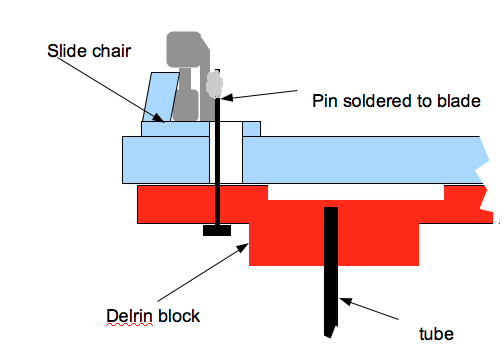
this is the idea, a delrin piece fixed under the sleeper, slight narrower then the sleeper and connected to the switch rail via a pin soldered to the rail I see no issues with lost motion , as the system should be slightly able to over drive the pins/tube to provide compensation any comments |
||
| Attachment: attach_2113_2668_Screenshot_2015-04-21_16.43.11.png 698 | |||
| Last edited on 21 Apr 2015 16:49 by madscientist |
|||
|
posted: 15 May 2015 11:41 from: Templotter
click the date to link to this post click member name to view archived images |
Haven't seen sleepers with patches of (tinned?) cladding like these. 3036_150722_350000000.jpg  Anyone know what they are please? Don |
||
| Last edited on 15 May 2015 12:23 by Templotter |
|||
|
posted: 15 May 2015 12:00 from: Martin Wynne
click the date to link to this post click member name to view archived images |
Templotter wrote: Haven't seen sleepers with patches of (tinned?) cladding like these.Hi Don, See: http://www.dccconcepts.com/track-trackmaking-parts/dccconcepts-track-and-trackmaking-parts/4mm-scale-pre-etched-sleepers-80-x-1-6-x-32 And explanations here: http://www.modelrailforum.com/forums/index.php?showtopic=28398 regards, Martin. |
||
|
posted: 15 May 2015 12:34 from: Templotter
click the date to link to this post click member name to view archived images |
Thanks very much Martin for that. Verry interesting. Will need to see if they (have any plans to) do 7mm. Don |
||
|
posted: 21 Apr 2016 07:44 from: Ewerthon_Mota
click the date to link to this post click member name to view archived images |
Don´t want to change the subject, but what material is this rail? The color is beautiful! It´s Nickel Silver? Or maybe it´s the light/outdoor? For me its the most realistic rail photo ever...  |
||
|
posted: 21 Apr 2016 09:55 from: Martin Wynne
click the date to link to this post click member name to view archived images |
Ewerthon_Mota wrote: Don´t want to change the subject, but what material is this rail? The color is beautiful! It´s Nickel Silver? Or maybe it´s the light/outdoor? For me its the most realistic rail photo ever...Hi Ewerthon, It is probably the stainless steel bullhead rail available from DCC Concepts, see: http://www.dccconcepts.com/track-trackmaking-parts/dccconcepts-track-and-trackmaking-parts/rail-bullhead-4mm-scale-stainless-steel-l-960mm-10-pack The problem with stainless steel is that it is difficult to solder, needing an aggressive acid flux and higher temperatures. Which must then be cleaned off to avoid future corrosion. This is especially necessary with electrical connections. In fact any form of acid flux is generally regarded as unsuitable for electrical work. Which means that for stainless steel electrical connections should normally be made mechanically by crimping, rivetting, clipping, etc. Alternatively, C&L can supply "Hi-Ni" nickel-silver rail which has a whiter colour than ordinary nickel-silver rail because of the higher Nickel content. And ordinary grey mild steel bullhead rail is available from several suppliers, which can look very good if kept clean. But it's liable to rusting in unheated conditions such as a garden shed, coastal atmospheres, etc. regards, Martin. |
||

| Please read this important note about copyright: Unless stated otherwise, all the files submitted to this web site are copyright and the property of the respective contributor. You are welcome to use them for your own personal non-commercial purposes, and in your messages on this web site. If you want to publish any of this material elsewhere or use it commercially, you must first obtain the owner's permission to do so. |