Templot Club Archive 2007-2020
|
|||
| author | remove search highlighting | ||
|---|---|---|---|
|
posted: 30 Nov 2015 22:27 from: mikewturner click the date to link to this post click member name to view archived images |
Hi guys Firstly apologies as am not really sure of the correct terminology for this type of track but can anyone point me in the right direction for details of block size, spacing etc etc. I assume that standard 2 bolt chairs were used? Regards Mike |
||
|
posted: 5 Dec 2015 10:09 from: John Shelley
click the date to link to this post click member name to view archived images |
mikewturner wrote: Hi guysI'm afraid that I can't help you directly, but I do have an LNER (GE Section) drawing of a proposal to use timber blocks instead of sleepers for siding renewals. Would that be of use or interest? John, from 33820 St Ciers sur Gironde |
||
|
posted: 5 Dec 2015 10:15 from: alan@york click the date to link to this post click member name to view archived images |
Is this the type of track? 2_050723_350000000.jpg  undefined undefined |
||
|
posted: 5 Dec 2015 12:14 from: Nigel Brown click the date to link to this post click member name to view archived images |
Came across a statement on RMweb which states that the subject is covered in Ian Rice's book on building finescale track. Don't have the book so can't verify it. Nigel |
||
|
posted: 5 Dec 2015 12:26 from: Matt M.
click the date to link to this post click member name to view archived images |
Concrete pot sleepers are covered in the late Andrew Dow's 'The Railway, British Track Since 1804. A worthwhile investment if you like track work. Yes there is a mention in Ian Rice's book with some thoughts on ways to model it. Regards Matt M. |
||
|
posted: 5 Dec 2015 12:30 from: Matt M.
click the date to link to this post click member name to view archived images |
And yes the drawing and photo in Andrew's book show two bolt chairs on the GWR version. There is a 1944 technical drawing from The Railway Gazette which I imagine would be a copy of the GWR drawing. Regards, Matt M |
||
|
posted: 5 Dec 2015 21:47 from: Matt M.
click the date to link to this post click member name to view archived images |
Hi Mike, There were three types of concrete pot used by the GWR. The basic dimensions are the same at 2ft-0½ inches long by 1ft-6½ inches wide. 5¼ inches high. The flat top area was 1ft-7½ inches long by 1ft-1½ inches wide. At the end of the flat area they have a 45 degree chamfer to the sides which aren’t perpendicular but appear to have a slope of up to 5 degrees. The corners are also chamfered from the flat top to the the base. The measurement at the base is 4⅝ inches. All three types used a ⅞ inch chair bolt. On the type A and B pots these are centred at 11 inches apart. Though the type B could also have them at 12 inches apart. The Type C was experimental and moved the chair bolt holes further to the outside edge of the pot. There is a ⅜ inch recess in the top of all of these types to take the tie bar. I’m not sure if the pots that didn’t require a tie bar had the recess. This goes in under the chair and is held in place by the inner chair bolt. As the the tie bar clears the pot it changes from being a flat 2½ inch x ⅜ inch flat bar to being L shaped with an extra 2½ inch drop on the return. this chamfered at each end at 45 degrees. The tie bar for the Type A and B is 4ft-5¼ inches long. The one for the Type C would be longer on the flat section due to the offset of the chair. The chairs sit on a ½ inch elm pad. The Type A has a 9 inch dome, that is about 1½ inches hit at the centre, cast into the bottom of the base between the about 3 inches wide, ½ inch high bolt mounting cutout. This you can’t see while in position. The other difference is there is a return chamfer around the bas at 45 degrees starting about 1½ inches from the bottom. The Type B and C simply go, not so quite, straight down to the base which has a rough bottom. There were two spacings used on 45ft track. Goods loops and sidings generally had 17 sleepers per length. Tie bar at the end of the track. Then 1 pair of pots without tie bars. Tie bar. Then 2 without. Tie bar. Then 2 without. Tie bar. Then 2 without. Tie bar. Then 2 without. Tie bar. 1 without. Tie bar. Lightly worked sidings had 16 sleepers per 45ft length. This is evenly spaced at 2 without tie bars between those with tie bars. I think that covers most of the salient points clearly. The drawing would make this clearer of course, but I hope this is useful to you to start with. Regards, Matt M. |
||
|
posted: 6 Dec 2015 21:28 from: mikewturner click the date to link to this post click member name to view archived images |
John Shelley wrote:mikewturner wrote:Hi guysI'm afraid that I can't help you directly, but I do have an LNER (GE Section) drawing of a proposal to use timber blocks instead of sleepers for siding renewals. Would that be of use or interest? Hi John Thanks for the offer but looks like Matt has given chapter and verse on the GW version! Regards Mike |
||
|
posted: 6 Dec 2015 21:30 from: mikewturner click the date to link to this post click member name to view archived images |
alan@york wrote:Is this the type of track? Hi Alan It's similar yes but not the same. Where is this as a matter of interest? Regards Mike |
||
|
posted: 6 Dec 2015 21:36 from: mikewturner click the date to link to this post click member name to view archived images |
Hi Matt Thank you for your very comprehensive reply. The description you give exactly matches the photo I've seen which is in a siding at Barmouth, although I remember seeing some in sidings at Croes Newydd North Fork too. I've looked in the Rice book and it gives some basic ideas on modelling but with what you've told me and the drawing if I can get a copy should give me an idea of how to model it. Regards Mike |
||
|
posted: 6 Dec 2015 21:59 from: alan@york click the date to link to this post click member name to view archived images |
Hi AlanIt's similar yes but not the same. Where is this as a matter of interest?RegardsMike Mike:Mallaig Extension!(the siding was possibly relaid during the war years)Alan |
||
|
posted: 6 Dec 2015 22:04 from: mikewturner click the date to link to this post click member name to view archived images |
Hi Alan Wow that I did not expect! Regards Mike |
||
|
posted: 6 Dec 2015 22:06 from: mikewturner click the date to link to this post click member name to view archived images |
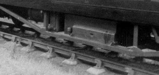
Hi guys This is the Barmouth shot I mentioned. Regards Mike |
||
| Attachment: attach_2186_2797_image.jpg 573 | |||
|
posted: 6 Dec 2015 22:30 from: Matt M.
click the date to link to this post click member name to view archived images |
Hi Mike, Concrete Pots (also known as 'twin-block' or occasionally 'monoblock' sleepers), were a wartime thing. Most of the big companies had been looking at reinforced concrete sleepers for a while. But earlier the cost benefits weren't there. There was no scrap value to a concrete sleeper, unlike timber and steel sleepers. Also concrete sleepers damaged during a derailment were not recoverable for further use, unlike timber. The LSWR had used Pot sleepers during WW1 due to wood shortages. And the same thing happened during WW2 and the austerity measures post war which made timber very hard to get for the railways. With the exception of the LNER which experimentally trialled some on running lines, this type of sleeper was used for sidings were the lack of resilience wasn't a problem. Lots of sidings were laid during the war. Andrew Dow goes into the development history of concrete sleepers in the UK along with the change to flat bottom rail in his book. Which will give you the drawing require and all the extra history for free... Really it is a worth while purchase. Glad to be of help. Matt M. |
||
|
posted: 7 Dec 2015 23:29 from: Tony W
click the date to link to this post click member name to view archived images |
undefined Below are a couple of pictures I took of some LNER pots that formed part of a short section of pot track in the goods relief on the lea valley line just north of Angel Road station North London. Although the rail and chairs have been removed, the outline of the chair can still be made out. Being LNER they were 3 bolt chairs. They are a different pattern to the GWR ones. I measured them at 2' 2" long, 12" wide and 6" deep. There is little or no taper below the corner chamfers. These particular two were at 2' 3" centres. They would certainly have been a war time replacement, possibly for bomb damaged track. From what I remember before the track was lifted, only every second or third pair of pots were tied together to hold them to gauge. It is something I hope the model a short section of one day. Tony W. 2151_071802_230000000.jpg  2151_071803_520000000.jpg  |
||
|
posted: 8 Dec 2015 00:41 from: Matt M.
click the date to link to this post click member name to view archived images |
Hi Tony, It was't just bomb damage replacement. They also needed to lay new sidings and loops due to the increased wartime goods traffic. Timber was hard to get and was reserved for main lines due to issues of resilience between the sleeper and the ballast. This is a particular problem as speed increases. With very few exceptions pots were only used in low speed applications. The pot sleepers are a compromise between material use and suitability for purpose. Hence the lack of tie bars on a majority of sleepers per length of rail. In a wartime and austerity settings they don't use too much steel or concrete. And don't use timber. During and post war a lot of energy was spent coming up with ways to make what would have previously been considered useless split timber sleepers be useable. Various clamps and straps and bolting formats were developed. It was that bad. Matt M. Nice, useful, photos by the way. |
||
|
posted: 31 Dec 2015 19:43 from: mikewturner click the date to link to this post click member name to view archived images |
Hi guys Thanks to Matt's suggestion Santa brought me a copy of Andrew Dow's book so I have the drawings :-) Regards Mike |
||
|
posted: 23 Jan 2016 03:57 from: Andrew Barrowman
click the date to link to this post click member name to view archived images |
Going a bit "off topic", but isn't there a French version that uses (or used) zig-zag ties? | ||
|
posted: 23 Jan 2016 14:39 from: Martin Wynne
click the date to link to this post click member name to view archived images |
Here is a scrap pile of GWR-pattern concrete pots. Sorry for not posting this photo earlier, I had forgotten I had it. 2_230937_340000000.jpg  2_230938_210000000.jpg  Martin. |
||
|
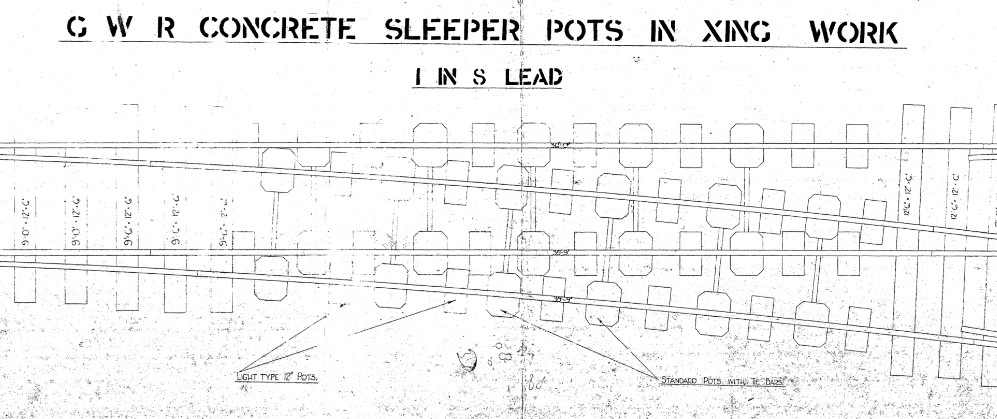
posted: 9 Feb 2016 19:07 from: mikewturner click the date to link to this post click member name to view archived images |
Hi guys This turned up today from an ex BR engineer and must say blew my mind completely as didn't expect pots to be used in pointwork! Regards Mike |
||
| Attachment: attach_2230_2797_image.jpg 423 | |||
|
posted: 19 May 2016 22:41 from: alan@york click the date to link to this post click member name to view archived images |
Turning from the prototype to the practical model railway, has anyone built track of this type. If so, did you have a baselayer below to stabilise the gauge, or was another method used to tie the blocks together. Thanks Alan@york |
||
|
posted: 22 May 2016 04:07 from: Andrew Barrowman
click the date to link to this post click member name to view archived images |
alan@york wrote: Turning from the prototype to the practical model railway, has anyone built track of this type. If so, did you have a baselayer below to stabilise the gauge, or was another method used to tie the blocks together.Haven't tried it Alan, but it would not be too difficult to make something like this on a 3D printer. If I was making them I would add low profile webs to connect the blocks. The webs would be hidden under the ballast. |
||


| Please read this important note about copyright: Unless stated otherwise, all the files submitted to this web site are copyright and the property of the respective contributor. You are welcome to use them for your own personal non-commercial purposes, and in your messages on this web site. If you want to publish any of this material elsewhere or use it commercially, you must first obtain the owner's permission to do so. |