Templot Club Archive 2007-2020
|
|||
| author | remove search highlighting | ||
|---|---|---|---|
|
posted: 31 May 2020 08:06 from: Julian Roberts click the date to link to this post click member name to view archived images |
Hi I've made a track plan for my intended layout, drawn exactly on the map as far as I am able. I wonder if this is as satisfactory as I think it is!? It's all done using the "beginner" tools but it looks fine to me - or maybe there are some improvements that can easily be made before I start actually making the trackwork? The only thing I know needs to be done (apart from finishing plotting one track into the shed) is putting in missing timbers on the 3 way turnout. I don't know if I can attach more than one file. I'll post again with the other file that Templot sent to my computer at the same time. |
||
| Attachment: attach_3077_3685_Kyle_track_layout_complete_30_may.box 112 | |||
|
posted: 31 May 2020 08:08 from: Julian Roberts click the date to link to this post click member name to view archived images |
Julian Roberts wrote: HiHere is the other file |
||
| Attachment: attach_3078_3685_Kyle_track_layout_complete_30_may.mecbox 93 | |||
|
posted: 31 May 2020 08:17 from: Julian Roberts click the date to link to this post click member name to view archived images |
3591_310313_500000000.jpg 3591_310315_430000000.jpg 3591_310315_430000000.jpg |
||
|
posted: 15 Jun 2020 06:54 from: Igor Kurgan
click the date to link to this post click member name to view archived images |
From your last picture, where the "parking" track is, i would use 2 or 3 pieces of track in differed curves to match the drawings better. | ||
|
posted: 15 Jun 2020 08:30 from: Julian Roberts click the date to link to this post click member name to view archived images |
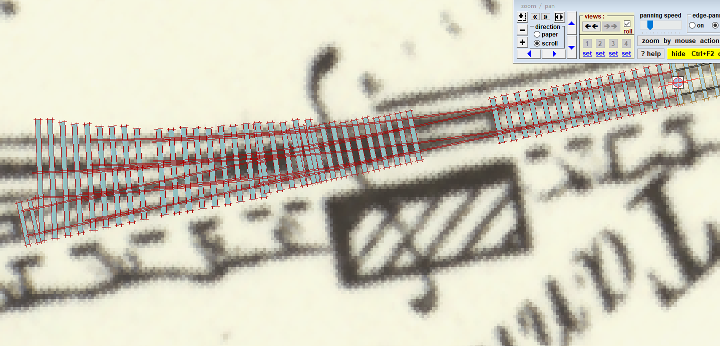
Igor, thanks. I have had a lot of help over the last week or so from another modeller in Scotland, and have learned a lot more about Templot. The track plan attached previously had a lot of problems of which I was unaware. One thing that was unsatisfactory was the 3 way by the turntable. It took me many hours and goes to get it to look like this, whereby it follows the map more or less precisely. It starts with the main line towards the slip on a negative curve of the maximum radius possible, overlength on the approach so that it goes about half way to the turntable. Then the RH turnout towards the engine shed is made using the Roam and F9 so that there's plenty of room behind. Then Templot creates the single sided 3 way, finished by using the Roam and F9 again. I was able to adjust the switch length too. What I can't manage to do is to get the start of the 3 way to where it says it is on the map - mine is quite a lot longer. The screenshot shows that Templot for some reason didn't put in all the sleepers, and the map is visible beneath, showing the toe of the 3 way. Whereas mine is about 8 sleepers longer. I don't think it matters at all but I wonder what is going on there. |
||
| Attachment: attach_3089_3685_3_way_No_1.PNG 108 | |||
| Last edited on 15 Jun 2020 08:37 by Julian Roberts |
|||
|
posted: 20 Jun 2020 17:01 from: Igor Kurgan
click the date to link to this post click member name to view archived images |
If i understand you correct? then this would be the problem: My best guess would be that your starting point: the normal turnout did not have the appropriate size and or curve. Timbering can be added later. First create a single piece of track that matches the curve of the main line. After you make the turnout from that piece of track, look for size. Click on the blue letters in that pop up menu and play with different sizes til it matches your satisfaction. You can still alter a lot on that turnout: size curve roam orbit. if all is good, i would make a copy and proceed to make the 3 way that i would like... Again a lot of options. I would start without timbering to get a better over view. I hope this will do your trick, my two cents. Best. |
||
|
posted: 22 Jun 2020 08:42 from: Julian Roberts click the date to link to this post click member name to view archived images |
Many thanks Ivan! In fact Martin very kindly designed me one.  See the Scalefour Forum http://www.scalefour.org/forum/viewtopic.php?f=5&t=7009 Cheers Julian |
||
|
posted: 2 Jul 2020 16:23 from: Julian Roberts click the date to link to this post click member name to view archived images |
Hi Martin Since the last post here you have very kindly again designed a revised tandem for me, posted on the Scalefour Forum http://www.scalefour.org/forum/viewtopic.php?f=9&t=7017&start=25 It certainly has the features in the photographs. I want to check as there are a few parts that show a minimum radius of 36". I think they are so short that they are not relevant to my own ruling radius of 48" but wanted to check. I design my stock and locos to be able to take quite punishing track without derailing. I would imagine these short bits are like a minor track defect? While posting on the subject, I notice you've smoothed out what was the ruling radius of about 52" on the connection to the single slip, to a much smoother 102" radius. I have two photos that show this section. The older one (with HR shunting signals) has a check rail. The newer one (with BR/LMS ground shunting signal) doesn't seem to have one. I surmise this bend was eased along with the other improvements but had intended to keep the tighter bend. Do you think that tight bend is a mistake on the map and it would have been unlikely to be such a sharp bend? I quite fancy an excuse for a sharp bend with check rail as a litmus test for stock. I've tried to upload the photos but maybe they are an invalid format here. They were both on my posts on my first thead on the S4Forum http://www.scalefour.org/forum/viewtopic.php?f=5&t=7009&p=76602#p76602 Many thanks for your advice Julian I attach the file |
||
| Attachment: attach_3106_3685_1_JULY_MARTIN_WYNNE_TANDEM_kyle_tandem_45degs.box 83 | |||
| Last edited on 2 Jul 2020 16:25 by Julian Roberts |
|||
|
posted: 3 Jul 2020 03:39 from: Martin Wynne
click the date to link to this post click member name to view archived images |
Hi Julian, When I post stuff it is mainly intended to be illustrative of the use of Templot, rather than a finished design to be used as-is. Only you know the constraints of your actual layout. It was an interesting tandem, having a split-deflection switch in the 2nd turnout. So not possible with the auto make tandem function. I tried to get the relative positions of the crossings, and the timber counts between them, to match the photo. And also to use standard crossing angles, rather than odd as-calculated angles. The length of 36" radius section is very short, and it's clear from the photo that the inner road is very tightly curved and a bit dog-legged. No doubt there was some gauge-widening to get large locos round it into the shed. However I have had another go. I pulled the 1:5.5 crossing back about a foot, and eased the 1:7.5 crossing to 1:8. The result is that the ruling curve on the inner curve is now around 1245mm (49") all through. File attached below. Sorry, you have lost me on the 102" radius curve. I'm not aware of changing it from anything else. The regulations require a continuous check rail on curves below 10 chains radius (104" in 4mm/ft) on running lines, but there is no such requirement for yards and sidings. It would depend on the frequency of derailments. I can't see any continuous check rails in the photo. File below. cheers, Martin. |
||
| Attachment: attach_3107_3685_kyle_tandem_modified.box 80 | |||
|
posted: 3 Jul 2020 08:17 from: Julian Roberts click the date to link to this post click member name to view archived images |
3591_030315_380000000.png |
||
|
posted: 3 Jul 2020 08:31 from: Julian Roberts click the date to link to this post click member name to view archived images |
Hi Martin I've managed to upload an image now. The check rail I mean is here on the left of the semaphore signal (as we look at the image). Just to be clear, when I designed the track plan following the map as closely as possible, this particular section was about 52" radius, followed by a relatively straight connection to the single slip. The redesign of the tandem you did incorporated this section, smoothed out to a more constant radius, which may be more like the photo with later signalling that I will post here. I will assume that was just for illustrative purposes too. Regarding the tandem - many thanks again. If you're saying your first version is more true to the photo I will probably build that one. Gauge widening through turnouts is fine, as discussed a few years ago. |
||
| Last edited on 3 Jul 2020 09:04 by Julian Roberts |
|||
|
posted: 3 Jul 2020 08:51 from: Julian Roberts click the date to link to this post click member name to view archived images |
3591_030349_490000000.png |
||
|
posted: 3 Jul 2020 11:51 from: Martin Wynne
click the date to link to this post click member name to view archived images |
Hi Julian, I have pushed the reverse curve in the tandem a bit wider, and pulled the 3rd crossing back from 1:7.5 to 1:6.5 angle. That has allowed a sharper curve in from the main line, which better matches the 1902 map. File below. cheers, Martin. |
||
| Attachment: attach_3109_3685_kyle_tandem_modified_more.box 81 | |||
|
posted: 3 Jul 2020 15:54 from: Julian Roberts click the date to link to this post click member name to view archived images |
I'm being rather spoiled here! Thanks again Martin. | ||
|
posted: 4 Jul 2020 08:22 from: Hayfield
click the date to link to this post click member name to view archived images |
Julian Roberts wrote: Hi MartinLooks to be a check rail followed by a catch point ? |
||
|
posted: 4 Jul 2020 08:57 from: Julian Roberts click the date to link to this post click member name to view archived images |
Yes Hayfield. Catch point is there whatever happens to track alignment. | ||
| Last edited on 4 Jul 2020 08:59 by Julian Roberts |
|||
|
posted: 9 Jul 2020 15:47 from: Tony W
click the date to link to this post click member name to view archived images |
Julian Roberts wrote: 3591_030315_380000000.pngHi Julian. Although the slip does not have interlaced timbering, it can be seen in the bottom left corner of the picture, that beyond the wing rails there is one long timber followed by interlaced sleepers. The ends of the sleepers for the far road are visible in the four foot of the near road and the chairs for the vee rails are staggered. Also note how the spacing of the chairs on the inside of the far check rail vary accordingly. Regards Tony. |
||
|
posted: 9 Jul 2020 19:30 from: Julian Roberts click the date to link to this post click member name to view archived images |
Thanks for pointing that out Tony. I hadn't looked carefully enough to see. I haven't sorted out that end of the single slip yet, it's looking like this, so plenty of scope still to have a go.3591_091427_470000000.png |
||
|
posted: 19 Aug 2020 12:50 from: Julian Roberts click the date to link to this post click member name to view archived images |
Here is my track plan for Kyle. It's more or less complete, to the extent I've printed out the turnouts (except the main line long one) and started construction with the right hand end off stage one. Still open to suggestions... It fits within an 8 foot length, though not quite onto two four foot boards - one has to be shorter, the other longer, by 3". I have done a re-design of the turnout that follows the 3 way so that the layout can fit onto two equal length boards. It also entails dividing the "Ash Road Turnout", which is a loose heel type. The problem there is that the loose heels would be on the very edge of the board, and I'm not sure whether that could work. I'm as yet uncertain in any case how to make this type. Two equal sized boards could easily fit front to front for transport, but I'm thinking just now that it won't be such an effort to adapt that idea to work for unequal lengths. I just wonder whether the difference of three inches - 4 ft 3 rather than 4 ft - is worth worrying about. Certainly no problem while we have a Skoda Octavia, but when that dies we may need to go smaller. |
||
| Attachment: attach_3135_3685_19_August_Baseboard_options_fine_adjusted.bgs3 61 | |||
| Last edited on 19 Aug 2020 13:12 by Julian Roberts |
|||
|
posted: 19 Aug 2020 12:51 from: Julian Roberts click the date to link to this post click member name to view archived images |
Here is the track file of the plan for unequal board lengths. | ||
| Attachment: attach_3136_3685_19_August_Final_Layout_assymetrical_board_lengths_unaltered_from_17_July.box 30 | |||
| Last edited on 19 Aug 2020 12:53 by Julian Roberts |
|||
|
posted: 19 Aug 2020 12:54 from: Julian Roberts click the date to link to this post click member name to view archived images |
And this is with the redesign of what I call the "Engine Shed Turnout" - quite easy to do - so it can fit onto equal length boards. | ||
| Attachment: attach_3137_3685_17_July_Final_layout_engine_shed_turnout_moved_two_sleepers_to_give_symmetrical_board_break.box 55 | |||
| Last edited on 19 Aug 2020 13:14 by Julian Roberts |
|||

| Please read this important note about copyright: Unless stated otherwise, all the files submitted to this web site are copyright and the property of the respective contributor. You are welcome to use them for your own personal non-commercial purposes, and in your messages on this web site. If you want to publish any of this material elsewhere or use it commercially, you must first obtain the owner's permission to do so. |