Templot Club Archive 2007-2020
|
|||
| author | remove search highlighting | ||
|---|---|---|---|
|
posted: 23 Jun 2020 11:50 from: Julian Roberts click the date to link to this post click member name to view archived images |
Hello Making a track plan on a map, I have an irregular diamond slip where at one end the crossing is 1:7 and at the other it is 1:9. I am muddled up about which way round the slip road goes. I think I've followed the instructions, I have copied each half diamond and made them into turnouts without sleepering, and done the other tasks to make them into slip roads. Logically that would imply to me that the switch for the 1:9 crossing goes actually adjacent to the 1:7 crossing - is that correct? And vice versa, the switch for the 1:7 crossing goes adjacent to the 1:9 crossing. Or is it the other way round? I have printed out the template and it looks perfectly OK to me, but it may not be correct, I've ended up putting the shorter switch by the 1:7 crossing. |
||
| Last edited on 23 Jun 2020 11:52 by Julian Roberts |
|||
|
posted: 23 Jun 2020 12:30 from: Martin Wynne
click the date to link to this post click member name to view archived images |
Hi Julian, The slip switches provided in Templot are intended to be used adjacent to V-crossings of similar angle. In each case the switch front length has been adjusted to ensure adequate clearance for the moving switch blades between the wing rail fronts, when pegged onto the TCP and MCP positions. They are merely suggestions of course. You can use any switch you like in a slip, if it fits better. If you are creating a slip to a specific prototype you would obviously want to use switches corresponding to those of the prototype railway company. For an irregular slip, you will probably need to use make simple link or make transition link on the slip roads to get a good fit between the switches. cheers, Martin. |
||
|
posted: 23 Jun 2020 13:35 from: Julian Roberts click the date to link to this post click member name to view archived images |
Hi Martin Thanks a lot for clarifying that. So my first go turns out to be right? - I attach the file just in case you had time to check. I'm assuming for 1950s BR I can have ordinary switches, and this seems to fit very well, and the link between the switches seems to be fine. Templot is amazing! Cheers Julian PS Please excuse the file title - I've got several different versions given titles of various levels of hyperbole! |
||
| Attachment: attach_3099_3706_IRREGULAR_SLIP_ABSOLUTELY_PERFECT_box_in_right_order.box 63 | |||
| Last edited on 23 Jun 2020 13:37 by Julian Roberts |
|||
|
posted: 23 Jun 2020 15:18 from: Martin Wynne
click the date to link to this post click member name to view archived images |
Hi Julian, Thanks for posting the file. That's looking good, nice to see an irregular slip.  At the 1:9 end you have used a 15ft switch, which is fine. But it needs moving forward (CTRL+F5 or 5) about 3mm so that the switch tips are supported on the timber, and can open behind the check rail. That will mean adjusting the slip road a fraction. How did you get on with make diamond-crossing at intersection? That had a recent major re-write in 226c. cheers, Martin. |
||
|
posted: 23 Jun 2020 17:26 from: Julian Roberts click the date to link to this post click member name to view archived images |
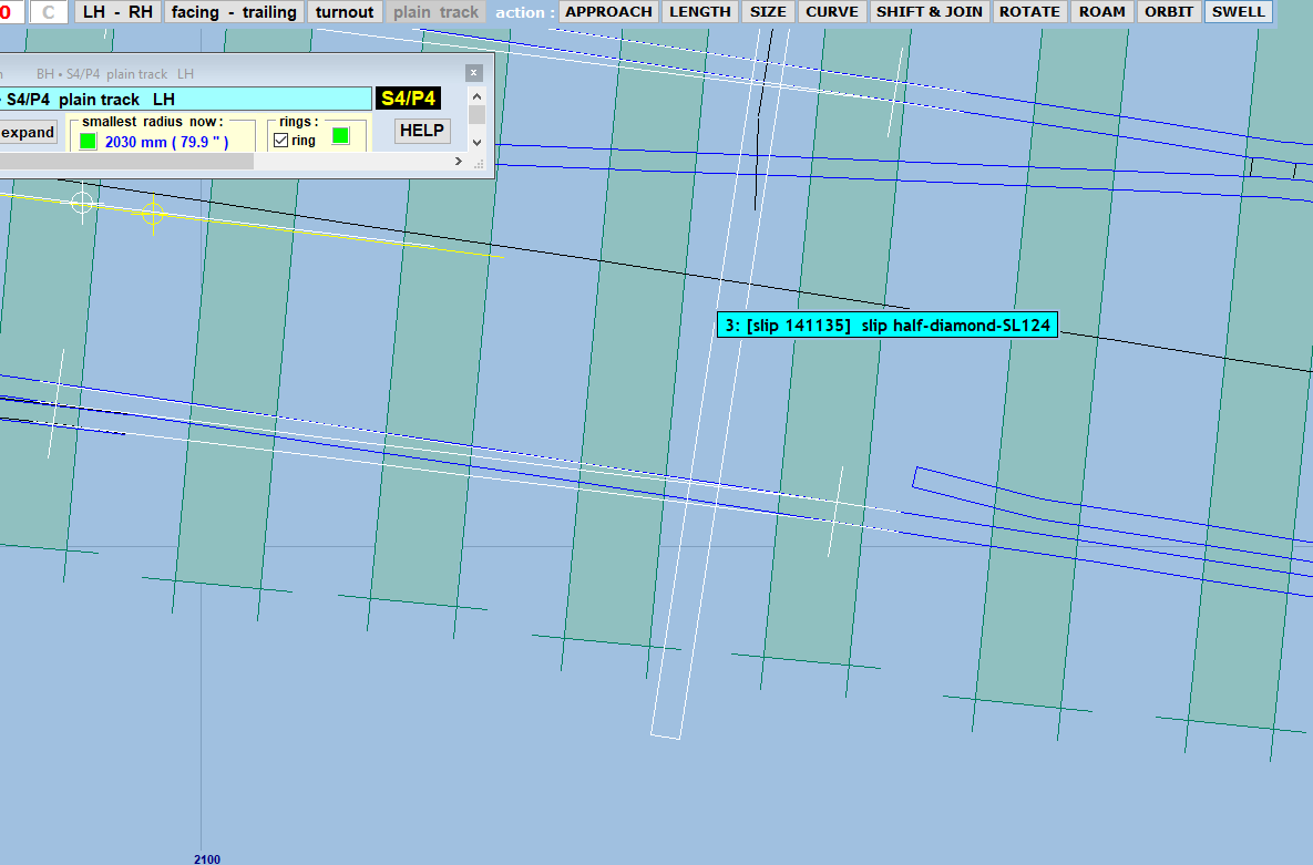
Hi Martin Thank you very much for taking the time to look at this. I don't remember deciding to use a 15ft switch rather than a slip switch - but if you say it's fine, I'm not altering it! I've slid the switch along using 5, and am not quite sure where the tips are. Hopefully I attach a screenshot. The tie bar is indicated, and there is a white line where I think the tips are - is that right, the white line indicates the tips? I think I did use the make diamond crossing at intersection - I remember it being a lot easier than following the tutorial making a ladder crossover. It was a few days ago. I have a question on making this formation but will do it as a separate topic. Cheers Julian |
||
| Attachment: attach_3101_3706_Slip_switch_detail_please_delete.PNG 74 | |||
|
posted: 23 Jun 2020 17:47 from: Martin Wynne
click the date to link to this post click member name to view archived images |
Julian Roberts wrote: The tie bar is indicated, and there is a white line where I think the tips are - is that right, the white line indicates the tips?Hi Julian, Yes, the marks indicate the tips of the blades and also the end of the planing (filing). On the diverging side the tip mark also indicates the position of the set in the stock rail. That's not actually the stretcher bar, it's just a guide slot mark for building the baseboard. The actual position of the stretcher bar(s) varies with different prototypes. cheers, Martin. |
||
|
posted: 26 Jun 2020 16:39 from: Julian Roberts click the date to link to this post click member name to view archived images |
Hi Martin I had to make the slip again, for various reasons. I looked for a long time for make diamond crossing at intersection - I expected it to be in tools - till I found it on the popup menu. It was easy to use, thanks. |
||

| Please read this important note about copyright: Unless stated otherwise, all the files submitted to this web site are copyright and the property of the respective contributor. You are welcome to use them for your own personal non-commercial purposes, and in your messages on this web site. If you want to publish any of this material elsewhere or use it commercially, you must first obtain the owner's permission to do so. |