Templot Club Archive 2007-2020
|
|||
| author | remove search highlighting | ||
|---|---|---|---|
|
posted: 26 May 2008 17:46 from: phileakins
click the date to link to this post click member name to view archived images |
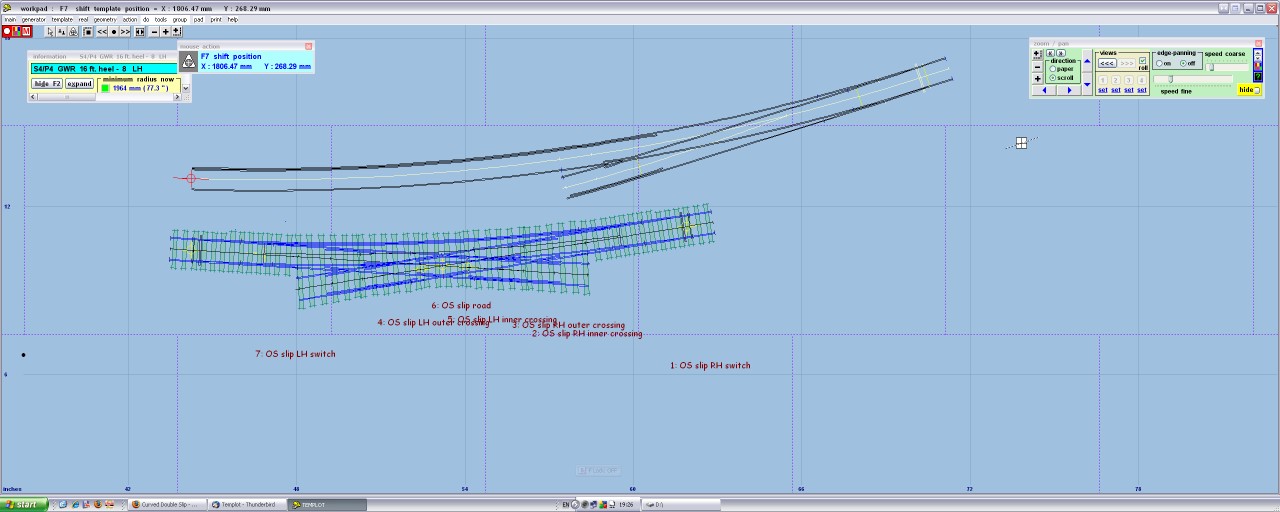
Hi all. As a complete TEMPLOT beginner I decided to try it all out by designing (using pug 0.91.c) a simple shunting plank. However, after a couple of false starts, I got carried away and the 'plank' is now 15 feet long and 2 foot 6ins wide! As it's S7 I needed to save space where I could or there would be no space in the house to errect it, so in the middle is this curved double slip which I offer for your comments. I didn't quite follow the sequence in Martin's video as I found it easier (after altering the switch of the turnout based on the curved diamond and saving a copy) to attach the turnout to the peg, MCP or TCP as appropriate, and then manipulating it by swapping/inverting the hand until it obviously lay on the diamond in the right position. Once there making the slip road was easy and guranteed to be right. I say this after making numerous mistakes and getting some very weird slips, incliding those in which the switch blades were outside the point entirely. Anyway, here it is. Phil |
||
| Attachment: attach_276_444_Double_slip_group_08_05_26_1206_14.box 660 | |||
|
posted: 26 May 2008 21:25 from: Phil O
click the date to link to this post click member name to view archived images |
Hi Phil I have had a look at your double slip and I see that your bottom slip road has minimum radius of 43" which scales out at 2.34 chains this will only be suitable for 0-4-0 locos and short wheel base or bogie wagons. Is this what you have in mind for using on your layout? Cheers Phil  |
||
|
posted: 26 May 2008 22:51 from: Jim Guthrie
click the date to link to this post click member name to view archived images |
phileakins wrote: I say this after making numerous mistakes and getting some very weird slips, incliding those in which the switch blades were outside the point entirely.Phil, Following on from what Phil O has said about the small radius of the slip road, this might be pushing your luck in Scale7 - even with 0-4-0 locos and short wheelbase wagon stock. However, designing your slip as an outside slip - with the switch blades outside the diamond - should increase the radius of your slip road and make things a bit easier. I always think that an outside slip is a more attractive formation - notwithstanding the extra crossings required.  Jim. |
||
|
posted: 26 May 2008 23:38 from: Martin Wynne
click the date to link to this post click member name to view archived images |
Jim Guthrie wroteFollowing on from what Phil O has said about the small radius of the slip road, this might be pushing your luck in Scale7Hi Jim, Phil has posted his track plan for discussion on RMweb at: http://www.rmweb.co.uk/forum/viewtopic.php?f=9&t=23593 Phil, that turnout to the right of the slip looks to be even sharper than the slip. If you upload the whole .box file rather than just the slip we could perhaps have a look at it. regards, Martin. |
||
|
posted: 27 May 2008 05:56 from: Jim Guthrie
click the date to link to this post click member name to view archived images |
Martin Wynne wrote: Jim Guthrie wroteMartin,Following on from what Phil O has said about the small radius of the slip road, this might be pushing your luck in Scale7Hi Jim, I noticed that earlier on this evening and I thought his station throat was getting a bit optimistic in S7 Phil, You have to plug 72"/1800mm radius in as your minimum in S7 and see how you get on, then go less than that under particular circumstances - like industrial trackage with short wheelbase stock. Jim. |
||
|
posted: 28 May 2008 01:13 from: phileakins
click the date to link to this post click member name to view archived images |
Thanks everyone. Once I've sorted out how to do "quotes" I'll reply to everyone individually. In the meantime, I've spent the day re-visiting the shapest turnouts and curves so ... watch this space! Your assistance is very much appreciated. Phil |
||
|
posted: 28 May 2008 21:00 from: phileakins
click the date to link to this post click member name to view archived images |
Thanks again folks - I'm attaching the .box files for the St Margarets project (suitably revised in view of your comments) and the revised curved double slip on its own. The original purpose of the project was the production of a rather large 'inglenook' style shunting layout, no passenger trains involved at all. Well, that was the intention, it rather grew as I played with Templot. I'm secretly quite chuffed with it. As you may gather, I don't much like dead straight lines! Phil - Yes, it was intended to be for an 0-6-0 (at most) and vans so I wasn't as concerned as I should have been about curves. Jim - I've only ever seen a rough sketch of an outside slip (there's one on the MRN pages you posted) and have no idea at all how to create the template! All suggestions gratefully received though. Thanks for pointing to my posting on RMWeb Martin. Re-reading it, I rather think my imagination carried me away. I have been doing some rough sketches though and thinking about a mock up using some of that card the re-cycling people won't take away ........ As I said, here they are for your comments and suggestions. Thanks. Phil |
||
| Attachment: attach_280_444_Double_slip_group_08_05_26_1206_14.box 442 | |||
| Last edited on 28 May 2008 21:01 by phileakins |
|||
|
posted: 28 May 2008 21:03 from: phileakins
click the date to link to this post click member name to view archived images |
Sorry, I can't seem to attach two files - here's the second. Phil [edit for typo] |
||
| Attachment: attach_281_444_st_margarets_08_05_28_1515_02.box 455 | |||
| Last edited on 28 May 2008 21:04 by phileakins |
|||
|
posted: 28 May 2008 23:46 from: Paul Boyd
click the date to link to this post click member name to view archived images |
Hi Phil Attached is an outside slip extracted from a plan I did years ago (and can be seen in the flesh* on my website at http://www.paul-boyd.me.uk/ - follow the model rail link then the "EM trackwork" link) Hopefully this will give you a pointer, and I think it should regauge from P4 to S7 fairly well as both are "scale" track standards. * sort of - the photos are of the EM version, the box file is P4 |
||
| Attachment: attach_282_444_OS_Slip.box 428 | |||
|
posted: 29 May 2008 00:15 from: phileakins
click the date to link to this post click member name to view archived images |
Paul Boyd wrote: Hi PhilThanks for that Paul - a truly mind boggling piece of trackwork! I've picked it apart through the 'box' but can't see where the slip road continuous check rail comes from. I take it there isn't an easy option?  Phil |
||
|
posted: 29 May 2008 00:35 from: Paul Boyd
click the date to link to this post click member name to view archived images |
Hi Phil Ah yes - the check rail! I've attached a screen shot with the slip road copied to current, and the blanking cancelled. Basically it's a bog standard turnout with the check rail extended ('real'=>'customize V-crossing'=>'wing and check rails...'). Once I have enough check rail, the turnout part is blanked off. There is good help text available on the dialogue box that opens up, but if you're stuck then shout! Incidentally, although my box file is a single outside slip, you can make a double outside slip in the same way. I have no idea if there are any prototype examples of that formation though! |
||
| Attachment: attach_283_444_cheat.PNG 1831 | |||
|
posted: 29 May 2008 01:30 from: phileakins
click the date to link to this post click member name to view archived images |
Cheers Paul - I've a spot on St Margarets where an extended check rail is needed. As to whether there is a prototype outside double slip, if it's possible, someone's done it! Thanks again. Phil |
||
|
posted: 29 May 2008 04:14 from: Martin Wynne
click the date to link to this post click member name to view archived images |
Paul Boyd wrote: Incidentally, although my box file is a single outside slip, you can make a double outside slip in the same way. I have no idea if there are any prototype examples of that formation though!Hi Paul, Phil, Double outside slips are certainly found in UK track, more commonly in yards than in running lines. Here is a well-known picture of one. Notice that it is not symmetrical, the left-hand slip road is longer and to an easier radius than the right-hand slip road. Which adds to the fun of building it. double_outslip.jpg  There is a picture of a double outside slip in a running line on page 43 of "A Pictorial Record of Great Western Signalling" (OPC). That one is also non-symmetrical. As usual, the photographer waited until there was a wheeled object in the way before taking a picture of the track. A special form of double outside slip is much used in Germany, and available in model form from Tillig: AAAA-85391.jpg  © http://www.internationalmodels.net That design has a common centre rail or casting. On the UK prototype it is essential that the centre rails are at least 6" apart in the middle, so that if one wears down more than the other, wheels running on one do not hit the side of the other rail. The problem of a wheel running on a worn rail hitting an adjacent rail is quite common in UK prototype track design, and has to be allowed for. Sometimes the ends of wing and check rails have 1/4" machined from the top to allow for wear on a close-by running rail. For example the nearest wing rail end on the left side in the picture in the signalling book might be such a case. Fortunately in models this is not something we have to bother about. (Apart from modelling it of course! 1/4" is 3 thou in 4mm scale, the thickness of thin paper.) regards, Martin. |
||
|
posted: 29 May 2008 04:32 from: John Lewis
click the date to link to this post click member name to view archived images |
Paul Boyd wrote: Incidentally, although my box file is a single outside slip, you can make a double outside slip in the same way. I have no idea if there are any prototype examples of that formation though!One example existed at Swindon on one of the down platform lines just at the down end of the down platform. Much of it can be seen in "Great Wesern Signalling" by Adrian Vaughan (OPC), Pg. 43. It replaced an even more hairy mixed gauge single slip, see eg "The Great Western at the turn of the Century" by AR Kingdom (OPC) Pg. 9, upper and partially in "Swindon Engineman". by G Shurmer & M Fenton (WSP), Pg 216. John |
||
|
posted: 29 May 2008 15:09 from: Paul Boyd
click the date to link to this post click member name to view archived images |
Martin wrote:Double outside slips are certainly found in UK track, more commonly in yards than in running lines. Here is a well-known picture of one.Excellent! That looks like a formation I have to find an excuse for, now I know they did exist |
||
|
posted: 29 May 2008 16:09 from: Brian Lewis
click the date to link to this post click member name to view archived images |
Martin Wynne wroteDouble outside slips are certainly found in UK track, more commonly in yards than in running lines. Here is a well-known picture of one. Notice that it is not symmetrical, the left-hand slip road is longer and to an easier radius than the right-hand slip road. Which adds to the fun of building it.Amazing! Now I have just got to build one of these. It would be fairly easy to construct - just start with the innermost straight section, as you normally so do in construction of tandems, slips and crossings, and work your way outwards. But with my limited skills with Templot, I would have to just scribe a few lines with a trammel and work from those - unless Martin came up with a tutorial.......... Regards Brian Lewis Carrs -- C+L Finescale. http://www.finescale.org.uk |
||
|
posted: 29 May 2008 18:17 from: phileakins
click the date to link to this post click member name to view archived images |
Paul has kindly posted his outside slip which is in P4 - How do I convert it to S7 please? Thanks. Phil PS I've looked at the outside double slip photo, the switches seem to be operating independently. Following the route of the bottom left switch is is set into the road on the right whereas the switch at the other end is set straight. The other slip road is the same. No point levers shown so either they're on a box (although not the on in the background) or a groundframe. Where was the photo taken please? |
||
| Last edited on 29 May 2008 18:24 by phileakins |
|||
|
posted: 29 May 2008 18:37 from: Martin Wynne
click the date to link to this post click member name to view archived images |
phileakins wrote: Paul has kindly posted his outside slip which is in P4 - How do I convert it to S7 please?Hi Phil, First select all the templates as a group (CTRL+A). Then go to the full gauges list (other gauges... menu item). Select the new gauge/scale standard you want on the list. Then click the convert group button at the top of the dialog. You will be ok converting from P4 to S7, but there are some points to bear in mind for other conversions -- see: topic 368 regards, Martin. |
||
|
posted: 29 May 2008 21:11 from: Alan Turner
click the date to link to this post click member name to view archived images |
Can I ask if this outside double slip was a GWR phenomenon or did other companies use it? In particular does anyone know of a Midland example? Alan |
||
|
posted: 29 May 2008 23:22 from: Martin Wynne
click the date to link to this post click member name to view archived images |
phileakins wrote: I've looked at the outside double slip photo, the switches seem to be operating independently. Following the route of the bottom left switch is is set into the road on the right whereas the switch at the other end is set straight. The other slip road is the same.Hi Phil, The slip is set for the straight road bottom left to top right. When worked from a box, both switches at one end of a double slip work together on one lever. Both switches at the other end work together on another lever. But the two ends are independent. That gives a total of 4 possible lever combinations, corresponding to the 4 possible routes through a slip. Only one route is ever available at any given time. In the picture it is bottom left to top right. In the picture there is the end of a check rail showing bottom right, and this slip is clearly part of a crossover to the running line on the right. The switches at the far end are rodded and interlocked from the box, and the ground signals at that end control access from the sidings to the running line. The lever working the far switches is probably also working the switch for the turnout out of sight in the running line bottom right, the usual arrangement for a crossover. Although in a yard like this the nearer switches are probably worked from independent hand levers (we can't see), in the picture all the switches are actually set exactly as they would be if rodded and interlocked from a signal box. Where was the photo taken please?Sorry, I don't know. Clearly it is pre-grouping. I scanned it from a 1922 book on trackwork design (Hepworth and Lee), but it is quite well-known and I have seen it published elsewhere. I think it is in the Gauge 0 Guild's trackwork manual. Anyone know the location? regards, Martin. |
||
|
posted: 29 May 2008 23:40 from: Martin Wynne
click the date to link to this post click member name to view archived images |
I wrote:Although in a yard like this the nearer switches are probably worked from independent hand levers (we can't see), in the picture all the switches are actually set exactly as they would be if rodded and interlocked from a signal box.On further thought I think the switch bottom right is also rodded from the box, hence the provision of two separate ground signals according to the setting of this switch. The signal wires will be running through a detector on this switch. If it was hand operated, almost certainly there would be only one ground signal for both roads. Also the hand lever would be on the left, away from the running line, and there is no sign of a suitable linkage. The switch on the bottom left might be a hand lever, or might be rodded from the box. However with the other three switches rodded I think it likely that this one would be too, and the lie of the switches is in accordance with this. double_outslip.jpg regards, Martin. |
||
|
posted: 30 May 2008 02:06 from: phileakins
click the date to link to this post click member name to view archived images |
Thanks Martin. When you think about it, would any signalling scheme allow ends of the same point to be separately controlled? Both ends are 'on the box' in some fashion, but it is plainly possible to set a route which could result in a run through. Of course we can't see the crossover behind the photographer and presumably the the mechanical locking wouldn't allow the clearing of a signal for a plainly wrong route, but (as I tell trainees) signals do not put an inpenetrable barrier across the railway ..... Phil |
||
|
posted: 30 May 2008 21:28 from: BeamEnds click the date to link to this post click member name to view archived images |
phileakins wrote: Thanks Martin.It could be that the lower left are hand points and the two dummies are of the "yellow" persuasion, the lower left road being used as a headshunt - though No.1 road to lower left route looks rather less used, so maybe not. Cheers Richard |
||
|
posted: 3 Jun 2008 03:25 from: JFS
click the date to link to this post click member name to view archived images |
Paul Boyd wrote: Hi PhilYour site is excellent - and very fast! I really like your facing point lock - does it work? Regards, Howard |
||
|
posted: 4 Jun 2008 20:56 from: Paul Boyd
click the date to link to this post click member name to view archived images |
Hi HowardYour site is excellent - and very fast!Thank you! It sped up once I dumped 123-Reg and Plusnet... I really like your facing point lock - does it work?I wish! I also wish I had a pound for every time I've been asked that |
||
|
posted: 10 Jun 2008 01:02 from: phileakins
click the date to link to this post click member name to view archived images |
Paul Boyd wrote:The thing is Paul - does that detector work?I really like your facing point lock - does it work?I wish! I also wish I had a pound for every time I've been asked that Very nice work, whose etchings, or are they yours? Phil |
||
|
posted: 10 Jun 2008 01:55 from: Paul Boyd
click the date to link to this post click member name to view archived images |
Phil wrote:Very nice work, whose etchings, or are they yours?The etchings are from Ambis Engineering, bought from Fourtrack Models. Catch is, Fourtrack only list 7mm scale stuff at the moment, so I don't know what the score is regarding 4mm scale trackwork from Ambis. The fouling bar is just a lump of 1/32" T-section brass, set to just clear the flanges! |
||
|
posted: 12 Jun 2008 00:48 from: phileakins
click the date to link to this post click member name to view archived images |
Paul Boyd wrote: The etchings are from Ambis Engineering, bought from Fourtrack Models. Catch is, Fourtrack only list 7mm scale stuff at the moment, so I don't know what the score is regarding 4mm scale trackwork from Ambis.Thanks Paul - as I'm S7 that isn't a problem. However, the Fourtrack web site is! I can't see any detailed description of the signalling products Ambis is selling - or is it just me? Any pointers please? Phil |
||
|
posted: 12 Jun 2008 13:06 from: Graham Idle
click the date to link to this post click member name to view archived images |
phileakins wrote: Paul Boyd wrote:The etchings are from Ambis Engineering, bought from Fourtrack Models. Catch is, Fourtrack only list 7mm scale stuff at the moment, so I don't know what the score is regarding 4mm scale trackwork from Ambis.Thanks Paul - as I'm S7 that isn't a problem. However, the Fourtrack web site is! Ambis can be contacted at 27 Stanhope Gardens, Ilford, Essex, IG1 3LQ or by email at alan@austinalan.wanadoo.co.uk . I hope this helps. Graham |
||
|
posted: 12 Jun 2008 13:41 from: richard_t
click the date to link to this post click member name to view archived images |
Graham Idle wrote:
Although, this is from the fourtrack models site: Richard. |
||
|
posted: 13 Jun 2008 02:20 from: Stephen Freeman
click the date to link to this post click member name to view archived images |
I have built an outside slip in P4 - there should be a photo on my website click on the scissors image and it should appear - I can let you have the boxfile if you wish - lots of partial templates I'm afraid. Stephen Freeman phileakins wrote: Cheers Paul - I've a spot on St Margarets where an extended check rail is needed. |
||
|
posted: 13 Jun 2008 05:33 from: John Lewis
click the date to link to this post click member name to view archived images |
Borg-Rail wrote: I have built an outside slip in P4 - there should be a photo on my website click on the scissors image and it should appear - I can let you have the boxfile if you wish - lots of partial templates I'm afraid. But what is your web site, please? John |
||
|
posted: 13 Jun 2008 10:53 from: Stephen Freeman
click the date to link to this post click member name to view archived images |
I seem to be having a problem putting a link in - works OK until I've sent the message but it doesn't seem to appear in the reply. I'll try it without the www bit but you won't be able to click on it of course. borg-rail.com/outsideslip.jpg John Lewis wrote: Borg-Rail wrote:I have built an outside slip in P4 - there should be a photo on my website click on the scissors image and it should appear - I can let you have the boxfile if you wish - lots of partial templates I'm afraid. |
||
| Last edited on 13 Jun 2008 10:58 by Stephen Freeman |
|||
|
posted: 13 Jun 2008 11:42 from: Martin Wynne
click the date to link to this post click member name to view archived images |
Borg-Rail wrote: I seem to be having a problem putting a link in - works OK until I've sent the message but it doesn't seem to appear in the reply. I'll try it without the www bit but you won't be able to click on it of course.Hi Stephen, Here's your picture -- excellent work! pp504592f7.jpg  http://www.borg-rail.com/_wp_generated/pp504592f7.jpg regards, Martin. |
||
|
posted: 13 Jun 2008 12:35 from: Paul Boyd
click the date to link to this post click member name to view archived images |
That's a beautiful piece of P&C work. Shame about the tiebars - I did spot your disclaimer |
||
|
posted: 13 Jun 2008 15:43 from: Stephen Freeman
click the date to link to this post click member name to view archived images |
Hi, Thanks, it's a single slip of course, in P4 - customer wanted the tiebars in PCB - not my choice you understand. Stephen Martin Wynne wrote: Borg-Rail wrote:I seem to be having a problem putting a link in - works OK until I've sent the message but it doesn't seem to appear in the reply. I'll try it without the www bit but you won't be able to click on it of course.Hi Stephen, |
||
|
posted: 13 Jun 2008 17:17 from: davelong click the date to link to this post click member name to view archived images |
Hi Stephen Looking at the other images on your site, are those Ambis stretcher bars you use or are they of your own design? Dave |
||
|
posted: 13 Jun 2008 19:46 from: Stephen Freeman
click the date to link to this post click member name to view archived images |
The others are all 0 Gauge and the stretcher bars are my own. In 4mm I usually use Masokits unless instructed otherwise as it's relatively easy to add a small piece of brass tube to them for under-board operation. style="BACKGROUND-COLOR: #ffffee" style="BACKGROUND-COLOR: #ffffee"Stephen davelong wrote: Hi Stephen |
||
|
posted: 13 Jun 2008 19:50 from: Stephen Freeman
click the date to link to this post click member name to view archived images |
All the others are 0 Gauge and are my own from PCB and wire - for 4mm I normally use Masokits tiebars as I can solder a small length of tube to them for under-board operation (not suitable for Solenoid operation though I think!) Stephen davelong wrote: Hi Stephen |
||
| Last edited on 13 Jun 2008 19:51 by Stephen Freeman |
|||
|
posted: 9 Sep 2008 00:29 from: davelong click the date to link to this post click member name to view archived images |
Evening all. After re reading this thread, as its been a while since its seen any updates. I'm intrigued with the double outside slip. As we've only managed to find references to two such slips, I was wondering whether people thought that I could realistically model one in an urban industrial setting in the Midlands for a 1970/80s themed layout based around a steel terminal? The idea being that with such a slip that it makes access to all four corners of a layout a lot more pleasing on the eye. To be honest I can get away with using a standard double inside slip, but the double outside looks like a real challenge. It's either the slips or a trailing point into a four way turnout ( three to the left one to the right), I can't quite decide on that either though. Dave |
||
|
posted: 12 Sep 2008 14:32 from: Martin Wynne
click the date to link to this post click member name to view archived images |
davelong wrote: I'm intrigued with the double outside slip. As we've only managed to find references to two such slips, I was wondering whether people thought that I could realistically model one in an urban industrial setting in the Midlands for a 1970/80s themed layout based around a steel terminal? Hi Dave, If you are talking private industrial sidings which had been in place since before say 1970 I think you can easily have such a double outside slip if you want one. It might be original construction from much earlier, or second-hand material re-claimed from elsewhere in the 1950s or 1960s. Tracks in industrial sidings can be very long-lived, and renewals are often second-hand. If you are talking BR-maintained track in the 1970/80s I think it's not impossible, but you would need some evidence of very old track still in use locally to be convincing. If it was really the only way to make the essential connections within the available space then why not? On the other hand BR tended not to build and maintain special one-off formations just for the fun of it because they look interesting! By the 1980s such old trackwork is much more likely to be either long-since out of use and buried in weeds, or to have been rationalised down to something much simpler and easier to maintain.regards, Martin. |
||


| Please read this important note about copyright: Unless stated otherwise, all the files submitted to this web site are copyright and the property of the respective contributor. You are welcome to use them for your own personal non-commercial purposes, and in your messages on this web site. If you want to publish any of this material elsewhere or use it commercially, you must first obtain the owner's permission to do so. |