Templot Club Archive 2007-2020
|
|||||||||||
| author | remove search highlighting | ||||||||||
|---|---|---|---|---|---|---|---|---|---|---|---|
|
posted: 12 Sep 2008 13:28 from: Stumpytrain
click the date to link to this post click member name to view archived images |
+++ This topic suffered corruption in the database and has been recompiled. +++ Hello, With a view to entering the 2mm Scale Association Layout Challenge I've been working on producing a plan to form a suitable base for Templot templates to be produced over. My chosen prototype is the "Old Station" at Bristol Temple Meads, which for those that don't know it can be seen here: http://tinyurl.com/5xywn4 As the track is entirely under an overall roof the track arrangement unfortunately doesn't show on Ordnance Survey plans. However, I recently chanced across a 1908 plan in the GWR Magazine. Although my period of interest is the late 50s, early 60s as far as I can ascertain there were little or no per way alterations since that time. Anyway, I've overlaid this GWR plan on an OS map and this is what I've achieved... templot1.jpg  It took a bit of skewing and stretching but I'm very pleased with the result. I'm going to work out more accurate stretcher bar locations and confirm the track centres of the 4 lines within the Brunel part of the shed next. The track centres are important as supporting columns for the drawing offices above were located between the lines in the original carriage / loco shed part. I'm still new to Templot really so any tips or suggests would be gratefully received. I hope to keep you posted! Cheers, Alex originally dated: 2008-03-11 00:12:43 _________________________ from: Paul Boyd Looks like an interesting project. I lived in Bristol for most of my life until I managed to escape, and I think it's a shame and somewhat ironic that the old station is just a car park now. As far as track spacing goes, this was originally built with broad gauge, and I vaguely remember seeing an engraving that shows four broad gauge tracks, so that should give you an idea. originally dated: 2008-03-11 10:12:13 _________________________ from: Nigel Brown Paul Boyd wrote: As far as track spacing goes, this was originally built with broad gauge, and I vaguely remember seeing an engraving that shows four broad gauge tracks, so that should give you an idea.For an engraving of its original state, see:- http://www.nrm.org.uk/exhibitions/bourne/gwr.asp It's possible that there are other relevant Bourne works. Nigel originally dated: 2008-03-11 13:20:27 _________________________ from: Roger Henry A couple of years ago BRILL ran an article on the resignalling of Bristol station and, if I recall correctly, it had a rather detailed track plan. I don't know if I still have a copy but is that the sort of information that you are searching for? Roger, Brisbane originally dated: 2008-03-11 13:07:14 _________________________ from: Paul Boyd Nigel wrote: For an engraving of its original state, see:- http://www.nrm.org.uk/exhibitions/bourne/gwr.aspIs it my imagination or poor eyesight, or does that show five broad gauge lines? originally dated: 2008-03-11 15:08:37 _________________________ from: Nigel Brown Paul Boyd wrote: Is it my imagination or poor eyesight, or does that show five broad gauge lines?Your eyesight is fine, or at least as good as mine; it does show five lines. Nigel originally dated: 2008-03-11 17:57:10 _________________________ from: Stumpytrain Hi all, Thank you for the interest! In broad gauge days there were 5 tracks within the train shed they were: * Arrival Platform * Engine Release * Carriage Siding * Carriage Siding * Departure Platform However, the major flaw of Brunel's design were the narrow platforms and the close proximity of the overall roof support columns to the platform edge. Thus the platforms were widened, and I guess the later platform widths date from the Digby Wyatt extension. I have to admit I forgot about the BRILL article, I'll try and locate my copy. I'm quite pleased with the accuracy of the plan I've produced but anything that it can be checked against is superb. Does anyone have any suggestions as to how I should start with Templot? Over the past few years I've done the branch line terminus tutorial a number of times but that's about it. Would people like to see a clearer / signalling diagram? Oh, I did I little mock up yesterday with some N gauge rolling stock... http://tinyurl.com/36kcgu Alex originally dated: 2008-03-11 18:02:12 |
||||||||||
|
posted: 12 Sep 2008 13:30 from: Stumpytrain
click the date to link to this post click member name to view archived images |
Hello, I've finally finished the baseboard for the layout! I've been playing with Templot a lot recently and I'm feeling a lot more confident. Whilst I agree it's good to learn from mistakes I was hoping someone could suggest a good route to build up my track plan. Where should I start, the simple crossover and work from there? Thank you in anticipation. Alex |
||||||||||
|
posted: 12 Sep 2008 14:16 from: Andrew Campbell click the date to link to this post click member name to view archived images |
You might find "Brunel's Bristol Temple Meads" by John Binding (OPC/Ian Allen - ISBN 0-86093-563-9) interesting and possibly useful. It's still in print. Best wishes for the project. Andrew |
||||||||||
|
posted: 16 Sep 2008 19:48 from: Martin Wynne
click the date to link to this post click member name to view archived images |
Stumpytrain wrote: I've been playing with Templot a lot recently and I'm feeling a lot more confident. Whilst I agree it's good to learn from mistakes I was hoping someone could suggest a good route to build up my track plan.Hi Alex, There are no fixed rules. Beginners in Templot tend to go for the brick-by-brick approach, possibly using the F7 snapping function to "clip" individual templates together, in a similar manner to other track-planning programs. This method is simple and quick, but it can produce a disjointed "train-set" look if you are not careful. More experienced users prefer to lay out the broad sweep of the running lines first, and then insert the turnout templates in them (or align the templates over them). This is the classic way to use Templot and the most likely to produce a prototypical sweeping feel to pointwork. Or you can use whatever mixture of methods suits your own way of thinking and working. There are always several different ways to arrive at a similar result. This video shows some of the basic track planning functions in Templot: starter video regards, Martin. |
||||||||||
|
posted: 16 Sep 2008 22:51 from: Martin Wynne
click the date to link to this post click member name to view archived images |
Hi Alex, I have just noticed that you have posted some pictures and plans on the Yahoo group. I'm copying them here on Templot Club for those members who are not regular visitors to the Yahoo group site.  regards, Martin. bristol_old_mockup.gif  bristol_old_plans.png  bristol_old_station.jpg  |
||||||||||
|
posted: 17 Sep 2008 06:47 from: Stumpytrain
click the date to link to this post click member name to view archived images |
Great work Martin! You've done some excellent work tweaking the photos and plans for presentation on the forum. My plan so far is to start with platform 14, some how extend into 15 with the correct reverse curve. Then build the crossover (10) as I know what the track centres should be, and create middle road. The sidings and platform 13 can then be built off platform 15 as I know what the track centres for those should be. After a print out to check that it works within the structures I can then create the scissors crossover that's on a curve, with one end as a 3 way and the 2 trap ends! Sound like a plan?!  Alex |
||||||||||
|
posted: 17 Sep 2008 14:09 from: richard_t
click the date to link to this post click member name to view archived images |
Although totally out of my time period and area, that last photograph is so atmospheric! But where's platform 14? |
||||||||||
|
posted: 17 Sep 2008 14:49 from: Martin Wynne
click the date to link to this post click member name to view archived images |
richard_t wrote: But where's platform 14?Hi Richard, Platforms: bristol_old_plats.png  Martin. |
||||||||||
|
posted: 17 Sep 2008 16:51 from: richard_t
click the date to link to this post click member name to view archived images |
Ah so no Platform 13 and 13A in those days.... MKC is shortly getting a 2A. |
||||||||||
|
posted: 17 Sep 2008 18:57 from: Jim Guthrie
click the date to link to this post click member name to view archived images |
Martin Wynne wrote: richard_t wrote:Martin,But where's platform 14?Hi Richard, It's only when you note the double use of the two platform faces that you realise the tremendous operating potential of the layout - it could take over from CJF's "Minories" [Edit] Meant to ask what happened in the track layout just off the plan to the left? Jim. |
||||||||||
| Last edited on 17 Sep 2008 18:59 by Jim Guthrie |
|||||||||||
|
posted: 17 Sep 2008 20:49 from: rodney_hills
click the date to link to this post click member name to view archived images |
Jim Guthrie wrote: Martin, Yes agreed , it mirrors, on a small scale, the six platform faces (2-7 North and South) and the accompanying three middle roads that figured in the LB&SCR 1906-7 rebuilding of their side of Victoria Station, London and, like 'Minories', would be fascinating to see operated with a high-intensity service as an exhibition tour-de-force. Regards, Rodney Hills |
||||||||||
|
posted: 17 Sep 2008 23:18 from: John Lewis
click the date to link to this post click member name to view archived images |
It could have been even more interesting prior to May 1892. Was this mixed gauge? | ||||||||||
|
posted: 18 Sep 2008 05:03 from: Stumpytrain
click the date to link to this post click member name to view archived images |
richard_t wrote: Ah so no Platform 13 and 13A in those days.... Hi Richard, Assuming you're talking about Bristol then there never has been a platform 13A! Alex |
||||||||||
|
posted: 18 Sep 2008 06:11 from: Stumpytrain
click the date to link to this post click member name to view archived images |
Jim Guthrie wrote: It's only when you note the double use of the two platform faces that you realise the tremendous operating potential of the layout - it could take over from CJF's "Minories" Jim, I think it's a great track plan! As you can see it can be very flexible. The best feature in my opinion in the direct connection from No2 siding to platform 12, a photo of the 9.15 Bristol - Gloucester waiting to leave the siding can be seen here: colin_maggs_bristol_old_station_01_large.jpg  Off to the left? Well, Bristol Old Station from the 1930s to 65 worked to Bristol East Signal Box. The lines controlled by Bristol East can be seen under a layer of paint in the top left hand corner of this photo of the signal box diagram: illuminated_diagrams.jpg  So from Old Station, via Bristol East you could get to the LMS Gloucester line via Mangotsfield, Lawrence Hill for Severn Tunnel, Severn Beach, Coalpit Heath etc and North Somerset Junction for Bath and the North Somerset branch. Alex |
||||||||||
|
posted: 18 Sep 2008 06:44 from: Stumpytrain
click the date to link to this post click member name to view archived images |
John Lewis wrote: It could have been even more interesting prior to May 1892. Was this mixed gauge? John, As far as I can tell the track layout that remained until closure in 1965 dated from 1878 when the signal box opened. This would have been when the platforms were widened, the number of tracks within the Brunel part reduced to 4 and the Digby Wyatt extension added. With the new curved trainshed intended for Great Western and Bristol & Exeter traffic the Old Station (as it would become called in 1891) was basically relegated to the Midland Railway. So, basically no... it wasn't mixed gauge! Alex |
||||||||||
|
posted: 18 Sep 2008 18:27 from: Jim Guthrie
click the date to link to this post click member name to view archived images |
Stumpytrain wrote: "promoted" surely, since it was the Midland Railway. Jim. |
||||||||||
|
posted: 19 Sep 2008 01:11 from: Brian Lewis
click the date to link to this post click member name to view archived images |
Jim Guthrie wrote:"promoted" surely, since it was the Midland Railway.No Jim. More a fate worth than death....... Regards Brian Lewis |
||||||||||
|
posted: 19 Sep 2008 02:07 from: John Lewis
click the date to link to this post click member name to view archived images |
Stumpytrain wrote:John,Thanks. John |
||||||||||
|
posted: 19 Sep 2008 02:09 from: John Lewis
click the date to link to this post click member name to view archived images |
Jim Guthrie wrote:"promoted" surely, since it was the Midland Railway.Err ... No! Definitely "relegated" (or "abandoned to ....") John |
||||||||||
|
posted: 19 Sep 2008 02:48 from: Jim Guthrie
click the date to link to this post click member name to view archived images |
Brian Lewis wrote: Jim Guthrie wrote:I can see that the Western supporters have never forgiven the Midland for nicking the Bristol and Gloucester from under the noses of the GWR."promoted" surely, since it was the Midland Railway.No Jim. More a fate worth than death....... Jim. |
||||||||||
|
posted: 20 Sep 2008 00:04 from: Bill_Lobb
click the date to link to this post click member name to view archived images |
Jim Guthrie wrote: Brian Lewis wrote: I can see that the Western supporters have never forgiven the Midland for nicking the Bristol and Gloucester from under the noses of the GWR.Well said, Jim. You are not alone.  Bill |
||||||||||
|
posted: 21 Sep 2008 03:13 from: Stumpytrain
click the date to link to this post click member name to view archived images |
Hi, Well I had a quick tinker with No.10 crossover today, I'm quite pleased with the results so far. Am I doing something wrong as I keep ending up with loads of templates in my storage box? Also I've got a gap in the rails between the two crossing vees. How did that happen? Is it because I've deleted the wrong template when trying to tidy my box? Anyway, I'm happy with the results so far. I'm not looking forward to doing the scissors crossover though! Alex |
||||||||||
| Attachment: attach_342_542_bristol_old_station_08_09_20_2208_57.box 550 | |||||||||||
|
posted: 21 Sep 2008 04:10 from: Martin Wynne
click the date to link to this post click member name to view archived images |
Stumpytrain wrote: Am I doing something wrong as I keep ending up with loads of templates in my storage box? Also I've got a gap in the rails between the two crossing vees. How did that happen? Is it because I've deleted the wrong template when trying to tidy my box? Hi Alex, The extra templates in the file which you uploaded are unused templates (showing with blue markers). Unused templates remain in the storage box after you wipe them from the background. They enable you to revert to a previous design at a later stage should you change your mind about something. If you don't want to create them, click delete to current on a background template when making design changes rather than wipe to current. Note also that all the items in the tools menu with the word "make" in them put the current template on the background for you. If you do it too, you will get 2 copies of the template on the background. The reason for the gap in the crossover is that you have the tracks at 24mm centre-to-centre spacing. But only turnout 10b has this set at geometry > adjacent track centres... menu item. Turnout 10a has the centres set to the default of 22.33mm,* and do > turnout road > is set to crossover (which terminates the turnout road at the crossover mid-point, CTRL-5 peg position). It does however line up, so I can only assume that you reset the default centres after creating the crossover. If on turnout 10a you first move the peg to anywhere except CTRL-5 and then change the turnout-side (TS) spacing to 24mm, the gap in the centre will be filled in. Or a quicker way to do that is to delete 10a, then delete 10b to current, then tools > make simple crossover. *corresponds to 6ft way between the tracks at 2mm/ft scale. regards, Martin. |
||||||||||
|
posted: 21 Sep 2008 20:05 from: Stumpytrain
click the date to link to this post click member name to view archived images |
Hi Martin, Thank you for the prompt and clear response. I think I'm starting to master the use of the storage box! With regards to the crossover I did indeed alter the track centre after creating the crossover. That's now been correct and I've had a tinker with creating the blocked crossing work. Have I done this correctly and is there an easier way than shoving timbers perhaps? I've has a go at extending in to Platform 15, and creating the adjacent lines at 13' centres. I'm going to print what I've done so far as the track centre for No.2 siding is the centre / ridge of the overall roof and I think this will be the easiest way to check. It's a shame there isn't a straight track from one end of the model to the other! Using this I've started musing over the scissors crossover. How I'm going to do this I don't know! I've attached the best photograph I have of it. Cheers, Alex |
||||||||||
| Attachment: attach_343_542_bristol_old_station_08_09_21_1451_22.box 490 | |||||||||||
|
posted: 21 Sep 2008 20:07 from: Stumpytrain
click the date to link to this post click member name to view archived images |
Oh, and here's the photograph! Alex |
||||||||||
| Attachment: attach_344_542_colin_maggs_bristol_old_station_02.jpg 5337 | |||||||||||
|
posted: 22 Sep 2008 02:22 from: Stumpytrain
click the date to link to this post click member name to view archived images |
My latest efforts, just a mock up really. Quite a beautiful piece of prototype trackwork... shame my track plan isn't to the same standard (yet!) Alex |
||||||||||
| Attachment: attach_345_542_bristol_old_station_08_09_21_2116_28.box 508 | |||||||||||
|
posted: 22 Sep 2008 03:03 from: John Lewis
click the date to link to this post click member name to view archived images |
There were some interesting signals at teh end of platform 13. | ||||||||||
|
posted: 22 Sep 2008 13:47 from: Martin Wynne
click the date to link to this post click member name to view archived images |
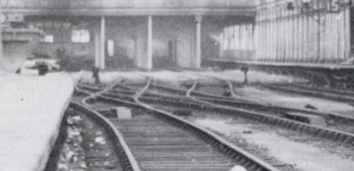
Hi Alex, A conundrum.  Looking at this photo of no.2 siding: Looking at this photo of no.2 siding:siding2.jpg  it is clear that the rail marked yellow is straight (and parallel to the walls), and that this switch is probably left-hand rather than the right-hand one in your draft design. However, in this photo (and the track plan you posted), it obviously isn't parallel with the walls, although on balance the impression gained is also of a straight turnout and a left-hand switch: siding2_1.jpg  Do the dates cover a significant track remodelling or the change in the number of tracks? Do you have any other pictures which might clarify things? regards, Martin. |
||||||||||
|
posted: 22 Sep 2008 14:41 from: Stumpytrain
click the date to link to this post click member name to view archived images |
John Lewis wrote:There were some interesting signals at teh end of platform 13. Yes, they're rather fabulous! Not as good as those on the end of Platform 15 though in my opinion. Stop signals in the same style as banner repeaters, presumably with a red band though! The picture shows those on the end of Platform 12 as well... banner_signals.jpg  Alex |
||||||||||
|
posted: 22 Sep 2008 14:45 from: Stumpytrain
click the date to link to this post click member name to view archived images |
Martin Wynne wrote:Hi Alex, I'm not aware of any track renewals between these photographs. Could it be an optical illusion caused by platform 15 curving away from the wall? Like so... siding2as.jpg  Personally I think the two pink lines are parallel and the two yellow lines are parallel. What do you reckon? In the mean time I'll try to collect together every photograph I have of the scissors! Alex |
||||||||||
|
posted: 22 Sep 2008 15:41 from: Martin Wynne
click the date to link to this post click member name to view archived images |
Stumpytrain wrote:I'm not aware of any track renewals between these photographs. Could it be an optical illusion caused by platform 15 curving away from the wall?Hi Alex, Hmm. I think you are right. I've now done what I should have done in the first place, and had a go at establishing the vanishing point for all the known horizontal parallel lines within the original building (yellow lines): siding2_2.jpg  Which makes it clear that I was wrong -- the no.2 siding track (pink line) doesn't continue straight through this turnout. There must be a curve in there between the end of the coach and the ground signal, although it's very difficult to see. However, I'm still inclined to say that the turnout itself is straight (and left-hand), because the near rails are clearly straight. (It's not possible for a curved object in a single plane to appear straight in a photograph.) This also corresponds to the impression from the photo of the scissors. regards, Martin. |
||||||||||
|
posted: 22 Sep 2008 18:01 from: Stumpytrain
click the date to link to this post click member name to view archived images |
Martin Wynne wrote:However, I'm still inclined to say that the turnout itself is straight (and left-hand), because the near rails are clearly straight. (It's not possible for a curved object in a single plane to appear straight in a photograph.) This also corresponds to the impression from the photo of the scissors. Martin, You are probably correct. The only reason I had it as a right hand was that the left hand route was the "normal" position and the right hand the "reverse." I've changed it to a left hand in Templot and it works a lot better. My latest box is attached if you're interested. Also, as promised are all the photographs of the turnouts relating to the scissors I've every seen... colin_maggs_bristol_old_station_02.jpg  http://www.alextrack.co.uk/library/images/railways/bristol_signalling/bristol_old_station_signal_box/colin_maggs_bristol_old_station_02_large.jpg harold_d_bowtell_old_station_down_midland.jpg  http://www.alextrack.co.uk/library/images/railways/bristol_signalling/bristol_old_station_signal_box/harold_d_bowtell_old_station_down_midland_xlarge.jpg nrm_650-59_1958.jpg  http://www.alextrack.co.uk/library/images/railways/bristol_signalling/bristol_old_station_signal_box/nrm_650-59_1958_large.jpg p_j_kelley_bristol_old_station.jpg  http://www.alextrack.co.uk/library/images/railways/bristol_signalling/bristol_old_station_signal_box/p_j_kelley_bristol_old_station_large.jpg real_photographs_6440.jpg  http://www.alextrack.co.uk/library/images/railways/bristol_signalling/bristol_old_station_signal_box/real_photographs_6440_large.jpg richard_hoskin_01.jpg  http://www.alextrack.co.uk/library/images/railways/bristol_signalling/bristol_old_station_signal_box/richard_hoskin_01_large.jpg t_nicholls_23_april_1963.jpg  http://www.alextrack.co.uk/library/images/railways/bristol_signalling/bristol_old_station_signal_box/t_nicholls_23_april_1963_large.jpg Alex |
||||||||||
| Attachment: attach_346_542_bristol_old_station_08_09_22_1253_06.box 512 | |||||||||||
|
posted: 22 Sep 2008 18:58 from: Martin Wynne
click the date to link to this post click member name to view archived images |
Hi Alex, That's a great collection of pictures, thanks for posting them. Especially this one: richard_hoskin_01.jpg I think there is enough there to have a go at gimping it to get the crossing angle. It seems clear that the diamond part is straight both ways, so it might be a good idea to create a standard straight scissors elsewhere first. Then shift and rotate it into place as a group. You can then adjust the turnouts and switches to the prevailing reverse curves at each end. The GWSG book has a drawing of a GWR scissors crossover in Fig. 46 on page 91. The angle isn't stated (unless I'm blind ), but I think it is 1:7.1/4 (and type 1 -- see below). That might seem an odd size, but there is a picture of a partial scissors at that angle on page 56, and the GWR tended to standardize components wherever possible.However, this one is obviously flatter than that, although the drawing and notes are a good guide to the arrangement of the fittings. The basic procedure to create an outline scissors crossover is: 1. start with a turnout of the required V-crossing angle, and TS track spacing centres. 2. do > turnout road > crossover 3. put the peg on TXP (CTRL-5) 4. do > snap to peg 5. tools > make mirror on peg 6. tools > make simple crossover 7. do > snap to peg 8. tools > make mirror on peg 9. store & background That works starting with a straight or curved turnout, and gets you all the essential rail alignments. After which you can create all the partial templates needed for the final design. If you start with a standard turnout the above procedure will most likely give you a type 1 scissors, with the V-crossings for the diamond in the turnout curves. However, it is much easier to construct a type 2 scissors, with the V-crossings for the diamond in extended crossing entry-straights on the turnouts. That produces a regular diamond with all its crossings of the same angle. To do that, start by extending the entry-straight on the first turnout. You can do that by mouse action in version 091c, which makes it much easier to see what you are doing and keep an eye on the radius. There is a bit of Jing video showing that mouse action in use at: http://screencast.com/t/q8zBFC9z and some notes about it at: http://www.rmweb.co.uk/forum/viewtopic.php?p=398910#p398910 regards, Martin. |
||||||||||
|
posted: 22 Sep 2008 19:50 from: Stumpytrain
click the date to link to this post click member name to view archived images |
Hi Martin, I've always considered myself to be disadvantaged compared to some prototype modellers in that I don't have many period photographs. But when I think about it I've actually managed to collect quite a few! It's a shame they were more interested in the locomotives and not the trackwork! Your method for creating scissors crossover is super quick. I've had a quick attempt at creating a GWR 1in9 scissors, grouping, moving and a little rotating. Of the type 1 variety as you explained but it looks quite impressive, if I do say so myself. 14a is still a right hand point, is that why I've ended up with what looks to be an un wanted reverse curve on the line between 14a and 12b? Also, the switch for 12b must be longer as on the plan and in the photographs the stretcher bar is another 6 timbers to the right. Thank you for your help so far! Alex |
||||||||||
| Attachment: attach_347_542_bristol_old_station_08_09_22_1449_03.box 477 | |||||||||||


| Posted: 6 Dec 2008 00:36 |
|
35th Message |
|
peterpeg click the date to link to this post click member name to view archived images spacer.gif 
|
maybe its been Harry Pottered!!... richard_t wrote: Although totally out of my time period and area, that last photograph is so atmospheric!
|
||
from:
Alan McMillan
| Edinburgh - United Kingdom |
click the date to link to this post

click member name to view archived images
Here is the box file of what I've done so far.
Alan
from:
Stumpytrain
| Totnes - United Kingdom |
click the date to link to this post
click member name to view archived images
Alan McMillan wrote:
Hi Alex
Here is the box file of what I've done so far.
Alan
Hi Alan,
Thank you so much for looking at my project. Sadly the box file only arrived minutes before I had to leave for work (I'm on nights this week) and Network Rail for some reason doesn't see the need to have Templot installed on its computers!
I will have a look when I get home in the morning. I can't wait!
Alex
from:
John Lewis
| Croydon - United Kingdom |
click the date to link to this post
click member name to view archived images
Thank you so much for looking at my project. Sadly the box file only arrived minutes before I had to leave for work (I'm on nights this week) and Network Rail for some reason doesn't see the need to have Templot installed on its computers!
Hence the delays to the WCML moderbisation?
from:
Stumpytrain
| Totnes - United Kingdom |
click the date to link to this post
click member name to view archived images
Hi Alex
Here is the box file of what I've done so far.
Alan
Top man! That's perfect, matches my scanned plan and photographs excellently. Right... time for bed!
Alex
from:
Alan McMillan
| Edinburgh - United Kingdom |
click the date to link to this post
click member name to view archived images
This is the latest progress. It's probably as much as I can do today - my other half wants me to paint the hall! I'll probably be able to finish it tomorrow or the day after. If you hide the pad labels, centrelines and guide marks, you'll get a better idea of what's been done.
Regards
Alan
from:
Alan McMillan
| Edinburgh - United Kingdom |
click the date to link to this post
click member name to view archived images
I've managed to get a bit more done this afternoon. The rails are finished. All I have to do now is the timbering.
Regards
Alan
from:
Stumpytrain
| Totnes - United Kingdom |
click the date to link to this post
click member name to view archived images
Hi Alex
I've managed to get a bit more done this afternoon. The rails are finished. All I have to do now is the timbering.
Regards
Alan
Wow, I'm gobsmacked. Thank you so much for your help, it looks fantastic. I'm still trying to work out if I'm looking forward to building that or not, it will look great though!
In case it effects the timbering, there is a single tongue trap point in the top left point coming out of No.2 siding. You can see it in the photograph here, just the to right of the generator:
http://www.alextrack.co.uk/library/images/railways/bristol_signalling/bristol_old_station_signal_box/nrm_650-59_1958_large.jpg
Thanks once again!
Alex
from:
Alan McMillan
| Edinburgh - United Kingdom |
click the date to link to this post
click member name to view archived images
I've noticed a couple of other things in that picture. The catch point on the track to the right of the generator, one track out from the platform also seems to have only one tongue. Also the far left turnout leading to the scissors appears to have a continuous check rail on it. I'll sort both out on the drawing.
Regards
Alan
from:
Alan McMillan
| Edinburgh - United Kingdom |
click the date to link to this post
click member name to view archived images
Here's the amended and additional catch points and continuous check rail.
Regards
Alan
from:
Alan McMillan
| Edinburgh - United Kingdom |
click the date to link to this post
click member name to view archived images
Here it is, finished!. The timbering under the scissors is a bit intensive and strange in places, but this is in order that all the crossings etc are properly supported. I hope it's all you were hoping it would be.
Regards
Alan
from:
Alan McMillan
| Edinburgh - United Kingdom |
click the date to link to this post
click member name to view archived images
Here is the amended box file as promised
Regards
Alan
from:
Stumpytrain
| Totnes - United Kingdom |
click the date to link to this post
click member name to view archived images
Thank you so much, its perfect! I hope to start work on building this right away, I have no excuse not to now!
I've turned the labels off so it's nice to look out and printed a few copies off now. What I was wondering is there any way of not printing the black line triangles (what are they) in order to make the plan clearer?
Cheers,
Alex
from:
Alan McMillan
| Edinburgh - United Kingdom |
click the date to link to this post
click member name to view archived images
Stumpytrain wrote:
Hi Alan,
Thank you so much, its perfect! I hope to start work on building this right away, I have no excuse not to now!
I've turned the labels off so it's nice to look out and printed a few copies off now. What I was wondering is there any way of not printing the black line triangles (what are they) in order to make the plan clearer?
Cheers,
Alex
Hi Alex
You're very welcome Alex - I'd like to see it when you have constructed it.
The black triangles are the start points for transition curves. As far as I am aware, if you go to Generator/Generator Settings and uncheck track centrelines, radial end marks and guide marks, then, again in generator, click Rebuild All Background, you'll get a template that is free of all that clutter. If not, I'm afraid you'd have to refer to Martin for that one. I'm passably good at using the programme but I've never had much experience with the printing side of things. My layout is not yet started!
Regards
Alan
PS There's another slightly modified box file in the Bristol thread. I found another bit of timbering that was not quite right to my eyes, so I had to fix it. Perfectionism is sometimes a curse!
from:
Stumpytrain
| Totnes - United Kingdom |
click the date to link to this post
click member name to view archived images
Anyway, today I made a little progress on starting the point work. After some fantastic assistance with the Templot track plan I've started preparing the PCB timbers.
track4_forum.jpg

There are some more photographs of the progress on my website here:
http://www.alextrack.co.uk/model_railways/bristol_old_station/track.shtml
Cheers,
Alex
from:
Alan McMillan
| Edinburgh - United Kingdom |
click the date to link to this post
click member name to view archived images
Good to see the track construction coming on. I went to your website to see more but all the picture links are dead. The other pages on the site are fine so it must just be that one.
Regards
Alan McMillan
from:
Stumpytrain
| Totnes - United Kingdom |
click the date to link to this post
click member name to view archived images
Thank you for letting me know about the broken links! It would help if I uploaded the right file...
 Anyway, it's all sorted now.
Last night I sweated the chair plates for one of the turnouts in place. Tedious work but it's starting to show a little more progress.
Alex
from:
Alan McMillan
| Edinburgh - United Kingdom |
click the date to link to this post
click member name to view archived images
It looks great!!
Keep up the good work.
Alan
from:
Stumpytrain
| Totnes - United Kingdom |
click the date to link to this post
click member name to view archived images
It looks great!!
Keep up the good work.
Cheers, Alan... your template is a real godsend though.
I've finished all the sleepers now.
track5_forum.jpg

Also chaired up half of the 'simple' crossover.
track6_forum.jpg

Alex
from:
Alan McMillan
| Edinburgh - United Kingdom |
click the date to link to this post
click member name to view archived images
Thanks - it was fun to do!
I'd love to build this myself, but not in 2mm - I'd end up with independently swivelling eyeballs!
Alan
from:
Stumpytrain
| Totnes - United Kingdom |
click the date to link to this post
click member name to view archived images
Hi Alex
Thanks - it was fun to do!
Well Bristol Old Station was intended as a trial for Bristol East Junction (my real passion!).
GWR_Track_635px.jpg

Let me know when you want to get started and I'll send you the background plan!

Alex
from:
Alan McMillan
| Edinburgh - United Kingdom |
click the date to link to this post
click member name to view archived images
412_250803_030000000.png

412_250803_310000000.png

Regards
Alan
from:
sm
| United Kingdom |
click the date to link to this post
click member name to view archived images
Hi Alex,
That's a great collection of pictures, thanks for posting them. Especially this one:
richard_hoskin_01.jpg
I think there is enough there to have a go at gimping it to get the crossing angle.
It seems clear that the diamond part is straight both ways, so it might be a good idea to create a standard straight scissors elsewhere first. Then shift and rotate it into place as a group. You can then adjust the turnouts and switches to the prevailing reverse curves at each end.
The GWSG book has a drawing of a GWR scissors crossover in Fig. 46 on page 91. The angle isn't stated (unless I'm blind
However, this one is obviously flatter than that, although the drawing and notes are a good guide to the arrangement of the fittings.
The basic procedure to create an outline scissors crossover is:
1. start with a turnout of the required V-crossing angle, and TS track spacing centres.
2. do > turnout road > crossover
3. put the peg on TXP (CTRL-5)
4. do > snap to peg
5. tools > make mirror on peg
6. tools > make simple crossover
7. do > snap to peg
8. tools > make mirror on peg
9. store & background
That works starting with a straight or curved turnout, and gets you all the essential rail alignments. After which you can create all the partial templates needed for the final design.
If you start with a standard turnout the above procedure will most likely give you a type 1 scissors, with the V-crossings for the diamond in the turnout curves. However, it is much easier to construct a type 2 scissors, with the V-crossings for the diamond in extended crossing entry-straights on the turnouts. That produces a regular diamond with all its crossings of the same angle.
To do that, start by extending the entry-straight on the first turnout. You can do that by mouse action in version 091c, which makes it much easier to see what you are doing and keep an eye on the radius. There is a bit of Jing video showing that mouse action in use at:
http://screencast.com/t/q8zBFC9z
and some notes about it at:
http://www.rmweb.co.uk/forum/viewtopic.php?p=398910#p398910
Hi Martin,
I stumbled across these instructions and found them easy to use, however how does one shorten the rail lengths on the crossover so they no longer cross over each other ?
Rgds,
StuartM
from:
ChrisC
| Watford - United Kingdom |
click the date to link to this post
click member name to view archived images
regards
ChrisC
Stumpytrain wrote:
Jim Guthrie wrote:It's only when you note the double use of the two platform faces that you realise the tremendous operating potential of the layout - it could take over from CJF's "Minories"
[Edit] Meant to ask what happened in the track layout just off the plan to the left?
Jim.
Jim,
I think it's a great track plan! As you can see it can be very flexible. The best feature in my opinion in the direct connection from No2 siding to platform 12, a photo of the 9.15 Bristol - Gloucester waiting to leave the siding can be seen here:
colin_maggs_bristol_old_station_01_large.jpg
Off to the left? Well, Bristol Old Station from the 1930s to 65 worked to Bristol East Signal Box. The lines controlled by Bristol East can be seen under a layer of paint in the top left hand corner of this photo of the signal box diagram:
illuminated_diagrams.jpg
So from Old Station, via Bristol East you could get to the LMS Gloucester line via Mangotsfield, Lawrence Hill for Severn Tunnel, Severn Beach, Coalpit Heath etc and North Somerset Junction for Bath and the North Somerset branch.
Alex
| Please read this important note about copyright: Unless stated otherwise, all the files submitted to this web site are copyright and the property of the respective contributor. You are welcome to use them for your own personal non-commercial purposes, and in your messages on this web site. If you want to publish any of this material elsewhere or use it commercially, you must first obtain the owner's permission to do so. |