Templot Club Archive 2007-2020
|
|||
| author | remove search highlighting | ||
|---|---|---|---|
|
posted: 4 Feb 2009 15:52 from: philchudley click the date to link to this post click member name to view archived images |
Hi All All the literature I have mentions the use of a fouling bar in conjugtion with facing point locks. These are quoted as typically being 50' in length. Despite numerous searches in my books, magazines, Internet, I have yet to find many photos of such fouling bars, and the ones I have found seem to be far short of 50'. This would apply to photos of mainline and branch lines. Would I be correct in assuming that fouling bars were largely superceeded by track circuits? This would seem to be reasonable for mainlines, but what about rural backwaters and branch lines? The period I am modelling (SR ex LSWR 1930's) branch line (similar in status to Swanage) So, if fouling bars were superceeded by track circuits, when did this occur, and by the mid thirties would most have gone? I would most appreciate your thoughts and expertise. Cheers Phil |
||
|
posted: 4 Feb 2009 16:26 from: micknich
click the date to link to this post click member name to view archived images |
If you contact me direct I will look through my old catolouges and text books. A 35ft lock bar seems more likerly than 50ft. If you have them some years ago Steve Hall wrote a good serious in "Model Railway Journal" from memory at least one lock bar shown in detal. Lock bars begain to be replaced by track circuits many years ago usualy on the more important lines first. Many a Branch still had Lock Bars when closed mid '60's. I don't think there are now any Lock Bars left on Network Rail. Mick Nicholson. | ||
|
posted: 4 Feb 2009 16:49 from: John Lewis
click the date to link to this post click member name to view archived images |
philchudley wrote: Despite numerous searches in my books, magazines, Internet, I have yet to find many photos of such fouling bars, and the ones I have found seem to be far short of 50'. This would apply to photos of mainline and branch lines. Fouling bars need to be longer than the distance between the inner wheels on the longest coach likely to use the line. With Maunsell coaches this inner wheelbase was 32 ft. In the case of Bulleid stock this was 38ft 6in, I believe, so I suspect fouling bars would be something like 40ft long. Was there a programme to fit longer bars with Bulleid's coaches (or BR Mk1?). If your line has GWR 70ft coaches (eg Weymouth) then they would have to be over 47ft. John |
||
|
posted: 4 Feb 2009 17:28 from: richard_t
click the date to link to this post click member name to view archived images |
philchudley wrote:Hi All A timely and useful thread. Although I model the 1980's I'd wondered why I'd not seen any fouling bars. One thing less to model for me |
||
|
posted: 5 Feb 2009 09:22 from: Howard
click the date to link to this post click member name to view archived images |
Mick Nicholson wrote: If you have them some years ago Steve Hall wrote a good serious in "Model Railway Journal"Issues 113 & 115. Howard. |
||
|
posted: 5 Feb 2009 15:51 from: Martin Wynne
click the date to link to this post click member name to view archived images |
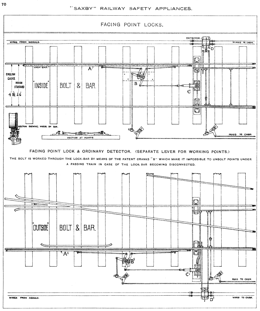
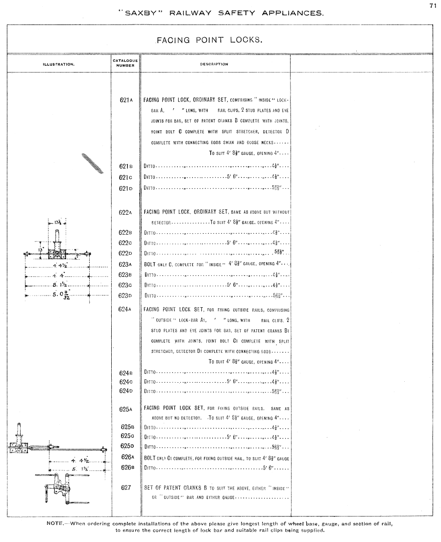
Mick Nicholson has kindly sent these two scans from the Saxby catalogue: saxby_fpl_1.png  saxby_fpl_2.png  Thanks Mick. Martin. |
||
|
posted: 5 Feb 2009 16:49 from: richard_t
click the date to link to this post click member name to view archived images |
Howard wrote:Mick Nicholson wrote:If you have them some years ago Steve Hall wrote a good serious in "Model Railway Journal"Issues 113 & 115. I've just scanned the article from issue 113, which is prototype information (where-as the article in 115 is 4mm implementation.). Mainly for my own use so I don't need to dig through my MRJ's to find it. It's a 12 page PDF (28MB), if anyone else wants a copy. |
||
|
posted: 5 Feb 2009 18:07 from: JFS
click the date to link to this post click member name to view archived images |
Re your comment about Track Circuits replacing fouling bars, I certainly know that at Midhurst (if that is rural enough) they did indeed replace a fouling bar with a short T/C when they rationalised to the single 'box. There were also numerous examples on main lines which were not otherwise track circuited at all (ie where Syke's Lock and Block was in use) I don't know about Swanage - but if you can get hold of / sight of the relevent copy of George Pryor's book of box diagrams, (now out of print, but try Amazon just in case) therein will surely be the answer. Regards, Howard |
||
|
posted: posted: 5 Feb 2009 19:32 from: R A Watson click the date to link to this post click member name to view archived images |
I have just had a quick look at the FASTLINE Videos Switch and Crossing Video Disc 2, and it has, in the maintenance of S & C section a BR training film which gives a "tutorial" on the construction and operation of F P L bars and associated equipment which will help your research. Whilst I must expres the usual "only an appreciative customer" comment I feel this series is a must have item for any user of this forum. Wally |
||
|
5 Feb 2009 19:32 from: rodney_hills
click the date to link to this post click member name to view archived images |
JFS wrote: (snipped) Hello, "S.B. Diagrams of the Great Western & Southern Railways by G.A. Pryer, Volume Two. S.R. lines in East Dorset" page 50 gives: Swanage (1899) - shows "MFB 5" (Mechanical Fouling Bar) in main line adjacent to turntable, away from pointwork. Swanage (1936) - shows post 30-06-1934 alterations which allowed trains to arrive at both platforms. TCs "A" over double slip, "B" over No.2 Platform entry points, "C" thence to outer crossover inclusive, "D" over main line straight road of outer crossover. Of the other diagrams in the same book, e.g. Verwood (1932) had one TC at the GF-worked south end. Two MFBs (14 & 15) at Hamworthy Jct (1898) , in advance of the "to Broadstone" junction points. Layout changed 1947, with TCs As all these MFBs have lever numbers and are depicted away from pointwork, they are perhaps a 'different animal'? Maybe MFBs located in pointwork are not shown on some SB diagrams, (eg Pryer's SRS ones) unlike TCs? Regards, Rodney Hills |
||
|
posted: 5 Feb 2009 20:46 from: Brian Lewis
click the date to link to this post click member name to view archived images |
richard_t wrote:I've just scanned the article from issue 113, which is prototype information (where-as the article in 115 is 4mm implementation.). Mainly for my own use so I don't need to dig through my MRJ's to find it. It's a 12 page PDF (28MB), if anyone else wants a copy. Err............. Have you received permission from the author - and the publisher? If not, what you are suggesting seems to be a violation of their respective IP rights..... Regards Brian Lewis |
||
|
posted: 5 Feb 2009 21:35 from: John Lewis
click the date to link to this post click member name to view archived images |
rodney_hills wrote:As all these MFBs have lever numbers and are depicted away from pointwork, they are perhaps a 'different animal'? Maybe MFBs located in pointwork are not shown on some SB diagrams, (eg Pryer's SRS ones) unlike TCs? What would be the function of a lever attached to a fouling bar? Surely the fouling bars attached to switches were not connected directly to the signal box themselves? John |
||
|
posted: 5 Feb 2009 21:57 from: micknich
click the date to link to this post click member name to view archived images |
A Fouling Bar and a Lock Bar are used for different purposes, though mechanically almost identical. A Lock Bar as shown in the drawing I posted ex S&F cat works in conjunction with the Facing Point Lock, bolt or plunger name depends on local terminology. It's purpose being to prevent the signalman withdrawing the lock and attempting to move the points with a train passing over them. The lockbar and bolt are worked by the same lever (Blue). A fouling bar and as the name suggests is laid down within the Fouling Point of converging lines and is again lever worked. The signalman being able to work the lever proves any engine or vehicles are clear of the "Fouling Point" and would not conflict/collide with traffic on an adjacent or converging line. A fouling or lockbar raises during the stroke of the respective lever. Obviously with a train stood on it this is not possible and the relevant interlocking between levers can't be freed. Today all is achieved by means of track circuits. Mick Nicholson. |
||
|
posted: 5 Feb 2009 22:11 from: rodney_hills
click the date to link to this post click member name to view archived images |
John Lewis wrote: rodney_hills wrote:As all these MFBs have lever numbers and are depicted away from pointwork, they are perhaps a 'different animal'? Maybe MFBs located in pointwork are not shown on some SB diagrams, (eg Pryer's SRS ones) unlike TCs?What would be the function of a lever attached to a fouling bar? Surely the fouling bars attached to switches were not connected directly to the signal box themselves? John, Hmm. Takes another look at Pryer Vol 2......... Swanage (1899) MFB 5 (the only MFB depicted) is beyond the heel end of facing points 6, which latter has FPL 5. but Hamworthy Jct (1898) has MFB 14 and MFB 15 in main and branch respectively beyond heel of facing junction points 12, which have FPL 11. Lever numbers 14 & 15 appear nowhere else on the diagram, which has a note that all spare levers were used up Feb 1901. No other MFBs. Regards, Rodney Hills |
||
|
posted: 5 Feb 2009 23:00 from: allanferguson
click the date to link to this post click member name to view archived images |
Locking bars were part of the Facing Point Lock mechanism, as pointed out by Mick Nicholson. Whenever the signalman moved the FPL lever the bar went up and down. A wheel flange would prevent this and therefore the movement of the FPL. In conjunction with the locking this ensured the points could not be moved while a train was standing on top of them. Therefore there would be a lever and rodding for the FPL, and another lever and rodding for the points. The gadgets referred to as MFB's sound to me more like treadles, which were designed to be depressed by wheels, and functioned rather like short track circuits. Glasgow Central had lots of them, in locations out of view of the signalmen, and there were operating instructions to ensure they were used, as in this extract from the Caledonian Railway Appendix to the WTT for 1915. What would be the function of a lever attached to a fouling bar? Surely the fouling bars attached to switches were not connected directly to the signal box themselves? |
||
| Attachment: attach_485_721_driver_on_fouling_bar.png 2525 | |||
|
posted: 6 Feb 2009 08:48 from: richard_t
click the date to link to this post click member name to view archived images |
Brian Lewis wrote:richard_t wrote:I've just scanned the article from issue 113, which is prototype information (where-as the article in 115 is 4mm implementation.). Mainly for my own use so I don't need to dig through my MRJ's to find it. It's a 12 page PDF (28MB), if anyone else wants a copy. Ah ... good point ... no I haven't so I respectfully withdraw my offer. It's a good issue mind you, so well worth seeking out. |
||
|
posted: 6 Feb 2009 12:26 from: Brian Lewis
click the date to link to this post click member name to view archived images |
richard_t wrote:Ah ... good point ... no I haven't so I respectfully withdraw my offer. It's a good issue mind you, so well worth seeking out.Well done Richard. I do feel sensitive about this, having 'rescued' some of my lost wax casting, which were given to a caster to be used as masters in the making of a pirated range of components. I hope you did not mind me mentioning this. Regards Brian Lewis |
||
|
posted: 6 Feb 2009 12:34 from: Ian Everett
click the date to link to this post click member name to view archived images |
Mick, I seem to remember a "Greek meets Greek" accident, within your current territory, caused by the unfortunate combination of timing of the moving of a facing point and positioning of the very same bars - albeit before the replacement of the signal box concerned? Ian Everett
|
||
|
posted: 6 Feb 2009 14:57 from: philchudley click the date to link to this post click member name to view archived images |
Many thanks to all, especially to Mike, most useful and valuable info. Have ordered the relevant back copies of MRJ (before the post of the PDF!) so have many directions for further investigations. Thanks again! Most appreciated |
||
|
posted: 6 Feb 2009 16:56 from: John Lewis
click the date to link to this post click member name to view archived images |
Ian Everett wrote: I seem to remember a "Greek meets Greek" accident, within your current territoryIs that what the Amricans call a "cornfield meet"? Ie a head-on collision. John |
||
|
posted: 6 Feb 2009 19:33 from: micknich
click the date to link to this post click member name to view archived images |
Ian was ref to a collision at Hull Paragon Feb 1927. By coincidence two ex NER 4-4-0's of the same class meet head on and were both written off. For some reason the book author captioned the picture "Greek meets Greek". Yes, our Yankie Cousins do ref to an head on smash as a "Cornfield Meet" but usually on a single line. Mick Nicholson. | ||
|
posted: 6 Feb 2009 20:37 from: John Lewis
click the date to link to this post click member name to view archived images |
What happened at slip (compound - GWR) crossings? There would appear to be no room for a facing point locking bar because of the closeness of the slip switches and the common crossings and their associated check rails. | ||
|
posted: 6 Feb 2009 20:44 from: micknich
click the date to link to this post click member name to view archived images |
See pages from S&F cat above. Mick. | ||
|
posted: 6 Feb 2009 21:45 from: John Lewis
click the date to link to this post click member name to view archived images |
I see what you mean - I had not taken that in. Thank you john |
||
|
posted: 7 Feb 2009 12:04 from: micknich
click the date to link to this post click member name to view archived images |
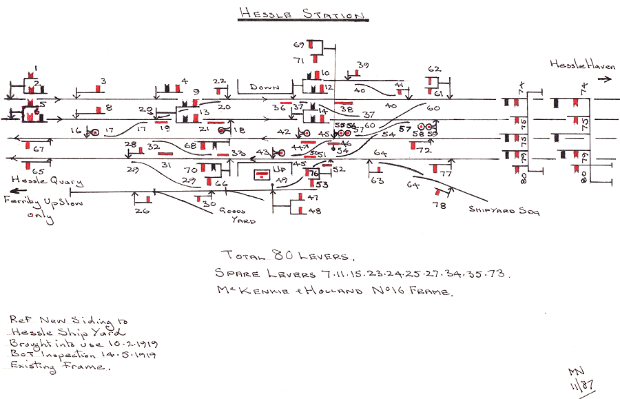
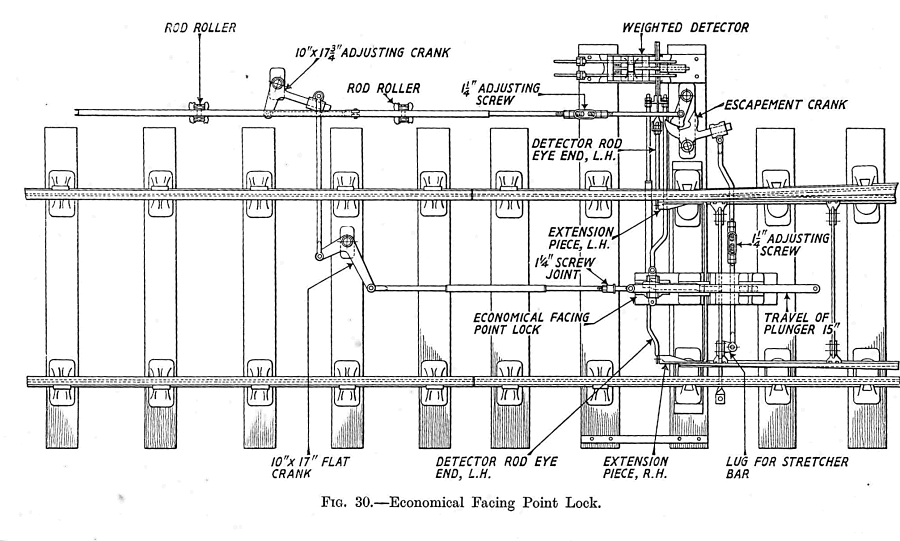
The attached may help to explain Mechanical Fouling Bars, examples shown are Down Slow No38, Down Fast No21, Up Fast No44 and Up Slow No31 and 50. I think they are self explanatory, but any queries please feel free to ask. hessle_signalling.gif  Below is an "Economical Facing Point Lock". It's from a pre-war LNER text book. There is no "Lockbar" in this instance. economical_fpl.png  Mick. |
||
| Please read this important note about copyright: Unless stated otherwise, all the files submitted to this web site are copyright and the property of the respective contributor. You are welcome to use them for your own personal non-commercial purposes, and in your messages on this web site. If you want to publish any of this material elsewhere or use it commercially, you must first obtain the owner's permission to do so. |