Hi Michael,
Can I make a suggestion?
S Scale chairs and timber base for testing
Make a fresh start in Templot then:-
Gauge > 22.45 S
Then [plain track], then [curve] , click on the blue radius in mm text to get a pop-up window:-
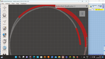
replace the 3143.25 with a / character and keep pressing <cr> until you get the trackpad back with a section of straight track, then click the [legth] button to shorten the template until the result fits within your build plate
Real > chairing > experimental chairing, and you should get this:-
click the [3D] to get the "experimental 3D" pop-up if it is not already displayed.
ensure all three tickboxes ticked
click on the colour box so that we can choose a different colour for the template that we are about to store.
In this example I am going to click the next colour along the bottom next to the existing colour, and then click [ok]
This allows us to to select a different colour for each timbering template brick we save.
Perform your favourite method of "store and background", for example just click on the buttonat the top with the two adjacent red down arrows.
This screen pops up:-
click "shwo storage box" to get this:-
note the colour, then click [show box list] button to get this:-
This will list all the templates that you have stored so far, and note that each template will display its chosen colour on the right hand side just before the identifier (PL001 in this case)
Close this window
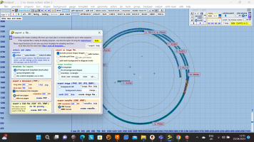
Now click on the [DFX/ STL file export] button that is on the bottom of the 3D pop-up.
This displays the export dialogue screen:-
In the group box in the top left hand corner I have ticked the "timbering brick only" radio button.
Note the colour in the box adjacent to "brick colour".
This means that all background templates (and shapes for that matter) that have been stored with this colour will be exported.
In the group box with the yellow background tick the [timbers only] button.
This will set all the pararmeters on tis screen so that just the timbering brick will be output, ie no chairs, but there will be sockets for the chairs.
In the "puce" group box in bottom left hand select the radio button for the type of print you will be performing
Rail
When you come to print "chairs only", you will need to have selected the correct rail profile from the pre-sets available, or if not available click on the [set custom rail] button in the top right hand box.
Now key in a description that is relevant, here is one I have made up:-
when you click [ok] you will get the "3D custom rail section dialogue" box, which will have values that default to BS-95R section scled to your chosen scale (i think, Martin might correct me here).
ANyway I would try the defaults first, unless you have already got your micrometer out.
I could not find values on the S society webiste for the rail they supply.
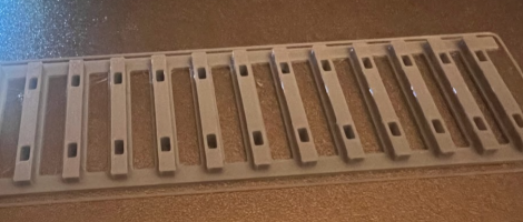
I would recomend that you try printing a section of plain straight timbering brick, and a set of corresponding S1 chairs to check the fit of your rail.
By print i mean :-
Export the STL from Templot, fix using the link in the bottom right corner, then slice with your slicer & print. No CAD involved (other than you might want to view the files.
If you need to adjust the rail section parameters in templot, then feed the info back to the forum so that Martin ahs the option of adding a pre-defined S scale rail to Templot, as this would then be very useful for those users of Templot who only ahve Templot and dont have access to CAD software like yourself.
I hope this helps
Steve
 Search
 Thanks.
")