 Search
Templot Club forums powered for Martin Wynne by XenForo :
TEMPLOT 3D PLUG TRACK - To get up to speed with this experimental project click here. To watch an introductory video click here. See the User Guide at Bexhill West.
-
The Plug Track functions are experimental and still being developed. Some of the earlier pages of this topic are now out-of-date.
For an updated overview of this project see this topic. For some practical modelling aspects of using Plug Track see Building 3D Track.
The assumption is that you have your own machines on which to experiment, or helpful friends with machines. Please do not send Templot files to commercial laser cutting or 3D printing firms while this project is still experimental, because the results are unpredictable and possibly wasteful.
Some pages of this and other topics include contributions from members who are creating and posting their own CAD designs for 3D printing and laser-cutting. Do not confuse them with Templot's own exported CAD files. All files derived from Templot are © Martin Wynne. -
The Plug Track functions are experimental and still being developed.
For an updated overview of this project see this topic. For some practical modelling aspects of using Plug Track see Building 3D Track.
The assumption is that you have your own machines on which to experiment, or helpful friends with machines. Please do not send Templot files to commercial laser cutting or 3D printing firms while this project is still experimental, because the results are unpredictable and possibly wasteful.
Some pages of this and other topics include contributions from members who are creating and posting their own CAD designs for 3D printing and laser-cutting. Do not confuse them with Templot's own exported CAD files. All files derived from Templot are © Martin Wynne.
You are using an out of date browser. It may not display this or other websites correctly.
You should upgrade or use an alternative browser.
You should upgrade or use an alternative browser.
00-SF Princes Risborough
- Thread starter Terry Downes
- Start date
Quick reply >

_______________
message ref: 6148

_______________
message ref: 6149
_______________
message ref: 6150
_______________
message ref: 6151
_______________
message ref: 6152
_______________
message ref: 6153
Hi Terry,
If you can join me right now on Zoom I can show you. Or if you say a later time today I will try to be there. Access link at:
https://85a.uk/templot/club/index.php?threads/zoom-meetings-access-links.620/latest
Everyone else welcome if they wish.
cheers,
Martin.
_______________
message ref: 6154
_______________
message ref: 6155
_______________
message ref: 6178
_______________
message ref: 6181
_______________
message ref: 6182
_______________
message ref: 6184
_______________
message ref: 6187
_______________
message ref: 6189
_______________
message ref: 6191
_______________
message ref: 6192
_______________
message ref: 6194
_______________
message ref: 6195
_______________
message ref: 6198
_______________
message ref: 6200
_______________
message ref: 6201
_______________
message ref: 6202
Hi Tony,
That may not be wise!")
I have just been reading this post from Judi in this topic:
https://85a.uk/templot/archive/topics/topic_3068.php#p21821
which may or may not be relevant in this case.
cheers,
Martin.
_______________
message ref: 6208
_______________
message ref: 6253
_______________
message ref: 6254
_______________
message ref: 6397
_______________
message ref: 7202
_______________
message ref: 7203
_______________
message ref: 10408

_______________
message ref: 10482
- Location
- Buckinghamshire, UK
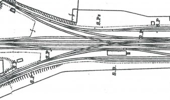
I have laid this station out many times over the past year and after starting several times and watching several zoom meetings I feel I need to actually pin the layout down and start constructing track etc. I'm modelling in 00-SF and starting at the north end crossover/divergence of two branch lines as I feel that once this crossover is sorted the rest should fall into place.
Can anyone advise whether the following template geometry would be good or needs amending before I get into the detail.
1. are semi-curved C10 good for a running line crossing? I used C10 as it seemed closest when overlaying on the 1921 scale map. I used semi-curved to give me a nice smooth curve from the mainlines to the diverging branch lines.
2. any advice on generating the middle crossover rails etc? I have used 6'6"" mainline centres and 7' other centres as this seemd right but, I'm open to advice.
message ref: 6148
Martin Wynne
Admin
- Location
- West of the Severn UK
- Info
- .
Enjoy using Templot?
 Thanks.
Please do not send requests for help direct to me via email.
Post your questions on the forum where everyone can see them and add
helpful replies.
@Terry Downes
Hi Terry,
Looking good.
But you have to be careful with the track spacing through scissors crossovers, because you can easily make it impossible to check all the V-crossings properly. As the main lines are straight, I can't see any reason not to have them at 6ft way (not ctrs as you marked), which would probably improve the checking. As it is I can see there may be checking problems:

But it's impossible to say for sure without your BOX file (can you attach it? Or a close zoomed-in screenshot would do). Generally for scissors you have to stick to 6ft way, or widen it a lot more than 6", to be able to fit all the check rails. But being in 00 changes that to some extent.
Yes C-10 turnouts are fine. There will be a speed restriction anyway for the curve, and only branch trains will be using the turnout roads.
is this going to be plug track on your laser-cut plywood?
cheers,
Martin.
Hi Terry,
Looking good.
But you have to be careful with the track spacing through scissors crossovers, because you can easily make it impossible to check all the V-crossings properly. As the main lines are straight, I can't see any reason not to have them at 6ft way (not ctrs as you marked), which would probably improve the checking. As it is I can see there may be checking problems:
But it's impossible to say for sure without your BOX file (can you attach it? Or a close zoomed-in screenshot would do). Generally for scissors you have to stick to 6ft way, or widen it a lot more than 6", to be able to fit all the check rails. But being in 00 changes that to some extent.
Yes C-10 turnouts are fine. There will be a speed restriction anyway for the curve, and only branch trains will be using the turnout roads.
is this going to be plug track on your laser-cut plywood?
cheers,
Martin.
message ref: 6149
- Location
- Buckinghamshire, UK
Hi Martin, box file attached. Yes, I'm planning on using plug track but not sure of final construction yet. Once I have this area laid out I will re-try laser cut timbers on my laser cutter but will also like to try FDM printed timbers with resin chairs as well as full resin timbers/chairs with some loose pegs etc.
Attachments
message ref: 6150
Martin Wynne
Admin
- Location
- West of the Severn UK
- Info
- .
Enjoy using Templot?
Thanks.
Please do not send requests for help direct to me via email.
Post your questions on the forum where everyone can see them and add
helpful replies.
@Terry Downes
Hi Terry,
Thanks for the BOX file. I have put a V-crossing on it to see the checking:

As you can see, it would be impossible to fit the required check rails at X. Derailments would be very likely.
At A it is borderline, but probably ok. Only at B is there full adequate checking from the opposite wing rail.
I will see what I can do to improve it.
cheers,
Martin.
Hi Terry,
Thanks for the BOX file. I have put a V-crossing on it to see the checking:
As you can see, it would be impossible to fit the required check rails at X. Derailments would be very likely.
At A it is borderline, but probably ok. Only at B is there full adequate checking from the opposite wing rail.
I will see what I can do to improve it.
cheers,
Martin.
message ref: 6151
Martin Wynne
Admin
- Location
- West of the Severn UK
- Info
- .
Enjoy using Templot?
Thanks.
Please do not send requests for help direct to me via email.
Post your questions on the forum where everyone can see them and add
helpful replies.
p.s. Terry,
Your tracks at 7ft way are breaking the BOT rules. Alongside double-track at 6ft way, they should be at 10ft way, or an absolute minimum of 9ft way if restricted by bridges, structures, etc.
This is to ensure that train crew can safely get down to the ground if the train becomes stationary for any reason.
This means that multiple tracks are usually in pairs, alternating 6ft way and 10ft way between them.
But modellers are frequently forced to break the rule, simply to fit tracks in the available space. Provided it looks significantly wider than normal double track, it usually looks the part.
cheers,
Martin.
message ref: 6152
- Location
- Buckinghamshire, UK
Hi Martin, I have re-visited the scaling of my scanned 1921 map and now believe that the running line tracks are closer to 7ft-6in and the alongside tracks are very close to 10ft as you suggested by BoT. Therefore, I have re-built my plan with these track gauges and attached box file. I would like to add a V-crossing to review the checking as you did previously but, I'm unable to locate the necessary function/process. A little guidance on this would be great if you get 10 mins.
Attachments
message ref: 6153
Martin Wynne
Admin
- Location
- West of the Severn UK
- Info
- .
Enjoy using Templot?
Thanks.
Please do not send requests for help direct to me via email.
Post your questions on the forum where everyone can see them and add
helpful replies.
@Terry DownesHi Martin, . A little guidance on this would be great if you get 10 mins.
Hi Terry,
If you can join me right now on Zoom I can show you. Or if you say a later time today I will try to be there. Access link at:
https://85a.uk/templot/club/index.php?threads/zoom-meetings-access-links.620/latest
Everyone else welcome if they wish.
cheers,
Martin.
message ref: 6154
Martin Wynne
Admin
- Location
- West of the Severn UK
- Info
- .
Enjoy using Templot?
Thanks.
Please do not send requests for help direct to me via email.
Post your questions on the forum where everyone can see them and add
helpful replies.
@Terry Downes
Hi Terry,
Here is the BOX file that we were working on earlier.
I will post the zoom recording in a few moments.
Now at: https://85a.uk/templot/club/index.php?threads/scruff-zoom-recordings.643/
cheers,
Martin.
Hi Terry,
Here is the BOX file that we were working on earlier.
Now at: https://85a.uk/templot/club/index.php?threads/scruff-zoom-recordings.643/
cheers,
Martin.
Attachments
message ref: 6155
- Location
- Buckinghamshire, UK
Can anyone advise/suggest how I should arrange timbers around the highlighted middle crossing. I don't think I should move the centre crossing timbers as they are positioned correctly. I can't move the underlying turnout timbers (shown with a red line through them) as they are positioned correctly for the top and bottom turnout v-crossings. So, I'm guessing I will have to split/splice timbers say along the green lines?

message ref: 6178
- Location
- Buckinghamshire, UK
Martin Wynne
Admin
- Location
- West of the Severn UK
- Info
- .
Enjoy using Templot?
Thanks.
Please do not send requests for help direct to me via email.
Post your questions on the forum where everyone can see them and add
helpful replies.
@Terry Downes
Hi Terry,
John's suggestion is good. A few 14" timbers would help a lot.
Some points to bear in mind:
Most crossing chairs are 8" wide. Standard timbers are 12" wide. Timbers can therefore be moved under them by up to 2" maximum each way. In Templot each click on the forward and back buttons moves the timber 1". One click is therefore fine, 2 clicks and you need to be careful.
On 14" timbers that becomes 2 clicks fine, 3 clicks be careful.
However, L1 bridge chairs are 11" wide, so if the chairing requires some of those, the scope for moving the timbers under them is much reduced. If you can't get timber under an L1 bridge chair, you can resort to using a half-bolted chair instead. (In a model you can represent those by cutting them from a P slide chair.)
Here's a possible solution using only 12" timbers:

When I have got the plug track done, it will be possible to have only the chairs showing on a separate duplicate template, so that they don't move as you shove the timbers under them. Not there yet.
cheers,
Martin.
Hi Terry,
John's suggestion is good. A few 14" timbers would help a lot.
Some points to bear in mind:
Most crossing chairs are 8" wide. Standard timbers are 12" wide. Timbers can therefore be moved under them by up to 2" maximum each way. In Templot each click on the forward and back buttons moves the timber 1". One click is therefore fine, 2 clicks and you need to be careful.
On 14" timbers that becomes 2 clicks fine, 3 clicks be careful.
However, L1 bridge chairs are 11" wide, so if the chairing requires some of those, the scope for moving the timbers under them is much reduced. If you can't get timber under an L1 bridge chair, you can resort to using a half-bolted chair instead. (In a model you can represent those by cutting them from a P slide chair.)
Here's a possible solution using only 12" timbers:
When I have got the plug track done, it will be possible to have only the chairs showing on a separate duplicate template, so that they don't move as you shove the timbers under them. Not there yet.
cheers,
Martin.
message ref: 6181
- Location
- Buckinghamshire, UK
Thanks John & Martin, I will have a go at using a few 14" timbers.
message ref: 6182
Tony W
Member
- Location
- North Notts
My solution to that would be to adjust the track spacing very slightly to get the timbers to overlap exactly. I presume you have the same situation at the other end of the formation.
Regards
Tony.
Regards
Tony.
message ref: 6184
Last edited:
Tony W
Member
- Location
- North Notts
Hi Terry.
Attached is my first attempt at a solution. Widening the track spacing moved things in the wrong direction, so I tried reducing the track spacing fractionally (about 0.3mm) until I got the timbers to align, but the timbering at the other end with the three diamonds looks like being a real headache although there must be a solution as the real thing must have met the same problem.
Regards
Tony.
Attachments
message ref: 6187
Tony W
Member
- Location
- North Notts
Having set the challenge, I thought I would have a go myself. I don't think this is the only solution to the timbering conundrum, but it should be workable. I have adjusted the checkrails, but the running rails still need sorting out at the crossings.
Regards
Tony.
Regards
Tony.
Attachments
message ref: 6189
Tony W
Member
- Location
- North Notts
Hi Hayfield.
I did consider straightening the timbers under the diamonds, but could foresee problems trying retain all the special chairs where they need to be.
Regards
Tony.
I did consider straightening the timbers under the diamonds, but could foresee problems trying retain all the special chairs where they need to be.
Regards
Tony.
message ref: 6191
Martin Wynne
Admin
- Location
- West of the Severn UK
- Info
- .
Enjoy using Templot?
Thanks.
Please do not send requests for help direct to me via email.
Post your questions on the forum where everyone can see them and add
helpful replies.
@Tony W
Hi Tony,
I know this is 00, so it's not possible to follow prototype dimensions. But it should be possible to follow prototype methods. For example it would be very rare for the prototype to vary the track spacing solely to improve the timbering layout. The local gang might do that when laying out a few sidings in a yard. But for a junction layout designed on a drawing board, it is important for the track spacing "way" dimension to be easily laid out on site, and later easily checked for movement. To that end it would usually be a round figure to the nearest inch or maybe half inch.
Terry set the spacing to give a prototype way dimension of 7ft-6in, which strikes me as entirely reasonable and a good match to the map. You changed it to 7ft-4.5/64" -- and I just don't believe it.
Also Terry had the switch toes staggered in the prototype fashion, to avoid conflicts in the drive rodding:

whereas you have put them in line. If there are long timbers across two turnouts of the same angle, the normal practice would be to stagger them by one timber space.
When difficulties arise in laying out the timbering, the prototype method would be to change the crossing angles and/or radii where necessary to get the chairing and checking to fit. Also there is no particular requirement for long timbers to be dead square-on across the formation, a small skew either way is acceptable if it simplifies the timbering.
Terry is now wishing he had never asked.
cheers,
Martin.
Hi Tony,
I know this is 00, so it's not possible to follow prototype dimensions. But it should be possible to follow prototype methods. For example it would be very rare for the prototype to vary the track spacing solely to improve the timbering layout. The local gang might do that when laying out a few sidings in a yard. But for a junction layout designed on a drawing board, it is important for the track spacing "way" dimension to be easily laid out on site, and later easily checked for movement. To that end it would usually be a round figure to the nearest inch or maybe half inch.
Terry set the spacing to give a prototype way dimension of 7ft-6in, which strikes me as entirely reasonable and a good match to the map. You changed it to 7ft-4.5/64" -- and I just don't believe it.
Also Terry had the switch toes staggered in the prototype fashion, to avoid conflicts in the drive rodding:
whereas you have put them in line. If there are long timbers across two turnouts of the same angle, the normal practice would be to stagger them by one timber space.
When difficulties arise in laying out the timbering, the prototype method would be to change the crossing angles and/or radii where necessary to get the chairing and checking to fit. Also there is no particular requirement for long timbers to be dead square-on across the formation, a small skew either way is acceptable if it simplifies the timbering.
Terry is now wishing he had never asked.
cheers,
Martin.
message ref: 6192
John Lewis
Member
- Location
- Selsdon, England
I have a copy of a GWR document dated 14th November 1921 that states "Our distance between centres of adjacent running rails is 11'-2½" which gives 2'-2½" clear between carriages of 9'-0"stock and 1'-8½" clear between carriages of 9'-6" stock." [The last dimension probably accounts for 9ft 6in wide coaches having mostly recessed doors.]
The accompanying drawing makes it clear that the 11ft 2½in dimension is measured from the centre of the adjacent tracks. (Attached - I hope it can be read). The 11ft 2½in dimension is near the top of the coaches.

The accompanying drawing makes it clear that the 11ft 2½in dimension is measured from the centre of the adjacent tracks. (Attached - I hope it can be read). The 11ft 2½in dimension is near the top of the coaches.
message ref: 6194
Martin Wynne
Admin
- Location
- West of the Severn UK
- Info
- .
Enjoy using Templot?
Thanks.
Please do not send requests for help direct to me via email.
Post your questions on the forum where everyone can see them and add
helpful replies.
@John Lewis
Thanks John.
That corresponds with the GWR permanent-way drawings showing 6ft-6in between adjacent gauge faces. With BS-95R bullhead rail, that gives a "6ft way" of 6ft-0.1/2in between the rails, being half an inch wider than all other companies. The GWR just had to be different in all things.
That is however the minimum track spacing. It can be wider where needed, and often is where the line was originally laid to broad gauge.
cheers,
Martin.
message ref: 6195
Martin Wynne
Admin
- Location
- West of the Severn UK
- Info
- .
Enjoy using Templot?
Thanks.
Please do not send requests for help direct to me via email.
Post your questions on the forum where everyone can see them and add
helpful replies.
@Terry Downes @Tony W
Hi Terry, Tony,
This has been driving me nuts. So I went back to first principles. Rescaled the map. Established that the best track spacing fit is actually 8ft way. Established that the best turnout fit to the branch curves is actually C-11.
I then staggered the turnouts by exactly one timber space (30") so that long square-on timbers can fit across exactly.
And the middle V-crossing turned out to be 1:5.13 and positioned exactly on one of the timbers:


And all nicely checked.
This is of course just luck, because this is 00-SF so it can't be expected to match the prototype very closely.
I will look at the other end of the diamond later.
cheers,
Martin.
Hi Terry, Tony,
This has been driving me nuts. So I went back to first principles. Rescaled the map. Established that the best track spacing fit is actually 8ft way. Established that the best turnout fit to the branch curves is actually C-11.
I then staggered the turnouts by exactly one timber space (30") so that long square-on timbers can fit across exactly.
And the middle V-crossing turned out to be 1:5.13 and positioned exactly on one of the timbers:
And all nicely checked.
This is of course just luck, because this is 00-SF so it can't be expected to match the prototype very closely.
I will look at the other end of the diamond later.
cheers,
Martin.
message ref: 6198
- Location
- Buckinghamshire, UK
Martin and All, Sorry I have not responded but, I’m currently away for a week in the Spanish Sun. I thought I would check my emails and wow… this topic has grown some. Thanks for all the suggestions and advice I’m looking forward to getting back into it later next week. Martin, when you say you have rescaled the map, did you download/acquire a different map with a true scale or did you manage to re-scale what I had scanned from a book?
message ref: 6200
Tony W
Member
- Location
- North Notts
Hi Martin.
I bow to your superior knowledge.
Regards
Tony.
I bow to your superior knowledge.
Regards
Tony.
message ref: 6201
Martin Wynne
Admin
- Location
- West of the Severn UK
- Info
- .
Enjoy using Templot?
Thanks.
Please do not send requests for help direct to me via email.
Post your questions on the forum where everyone can see them and add
helpful replies.
@Terry Downes
Hi Terry,
I first loaded the tiled georeferenced map from the NLS. This is the 1897 map which doesn't include the main line to Bicester:
https://maps.nls.uk/geo/explore/#zoom=18.6&lat=51.71994&lon=-0.84410&layers=168&b=8
This established the correct scaling for 4mm/ft.
Unfortunately the later 1919 map is not avaiIable georeferenced, which makes scaling the NLS sheets tricky:
https://maps.nls.uk/view/104182820
So I made a screenshot from that, loaded it as a picture shape, set it temporarily transparent, and scaled it over the 1897 map until it matched exactly.
Then deleted the 1897 map.
That's the usual method to scale scanned maps where you don't have any scaling information for the scan. Find a map which you can scale, set the unknown one transparent, and align it over the first one. We can do that in a Zoom meeting if anyone is interested? Templot includes several options for the scaling origin to make it easy.
cheers,
Martin.
message ref: 6202
Martin Wynne
Admin
- Location
- West of the Severn UK
- Info
- .
Enjoy using Templot?
Thanks.
Please do not send requests for help direct to me via email.
Post your questions on the forum where everyone can see them and add
helpful replies.
@Tony WHi Martin.
I bow to your superior knowledge.
Regards
Tony.
Hi Tony,
That may not be wise!
I have just been reading this post from Judi in this topic:
https://85a.uk/templot/archive/topics/topic_3068.php#p21821
which may or may not be relevant in this case.
cheers,
Martin.
message ref: 6208
- Location
- Buckinghamshire, UK
Hi Martin, could I possibly grab a copy of the box file and map/shape file if you still have them? I should be getting back into this over the next few days...@Terry Downes
Hi Terry,
I first loaded the tiled georeferenced map from the NLS. This is the 1897 map which doesn't include the main line to Bicester:
https://maps.nls.uk/geo/explore/#zoom=18.6&lat=51.71994&lon=-0.84410&layers=168&b=8
This established the correct scaling for 4mm/ft.
Unfortunately the later 1919 map is not avaiIable georeferenced, which makes scaling the NLS sheets tricky:
https://maps.nls.uk/view/104182820
So I made a screenshot from that, loaded it as a picture shape, set it temporarily transparent, and scaled it over the 1897 map until it matched exactly.
Then deleted the 1897 map.
That's the usual method to scale scanned maps where you don't have any scaling information for the scan. Find a map which you can scale, set the unknown one transparent, and align it over the first one. We can do that in a Zoom meeting if anyone is interested? Templot includes several options for the scaling origin to make it easy.
cheers,
Martin.
message ref: 6253
Martin Wynne
Admin
- Location
- West of the Severn UK
- Info
- .
Enjoy using Templot?
Thanks.
Please do not send requests for help direct to me via email.
Post your questions on the forum where everyone can see them and add
helpful replies.
@Terry Downes
Hi Terry,
Sure, attached below.
But I haven't done any more with it since posting it, so over to you to complete the diamonds.
cheers,
Martin.
Hi Terry,
Sure, attached below.
But I haven't done any more with it since posting it, so over to you to complete the diamonds.
cheers,
Martin.
Attachments
message ref: 6254
Tony W
Member
- Location
- North Notts
If the track centers are different then there is no choice but to start from scratch.
Regards
Tony.
Regards
Tony.
message ref: 6397
- Location
- Buckinghamshire, UK
Hi Martin, could You possibly fix a large stl file for me? its too large to attach or to fix via online fixer.
message ref: 7202
Martin Wynne
Admin
- Location
- West of the Severn UK
- Info
- .
Enjoy using Templot?
Thanks.
Please do not send requests for help direct to me via email.
Post your questions on the forum where everyone can see them and add
helpful replies.
@Terry Downes
Hi Terry,
Sure. Just send it to me as before.
Or see instead:
https://85a.uk/templot/club/index.php?threads/experimental-plug-track-continued.673/post-7205
cheers,
Martin.
Hi Terry,
Sure. Just send it to me as before.
Or see instead:
https://85a.uk/templot/club/index.php?threads/experimental-plug-track-continued.673/post-7205
cheers,
Martin.
message ref: 7203
Martin Wynne
Admin
- Location
- West of the Severn UK
- Info
- .
Enjoy using Templot?
Thanks.
Please do not send requests for help direct to me via email.
Post your questions on the forum where everyone can see them and add
helpful replies.
@Terry Downes
Hi Terry,
Recent discussions in this topic have been about Templot and plug track generally, rather than specific to Princes Risborough. So I'm going to move them to the plug track topic, before replying to your latest post.
cheers,
Martin.
Hi Terry,
Recent discussions in this topic have been about Templot and plug track generally, rather than specific to Princes Risborough. So I'm going to move them to the plug track topic, before replying to your latest post.
cheers,
Martin.
message ref: 10408
Justme Igor
Member
- Location
- Westwoud The Netherlands
Those would be the same problems as i would encounter when i am going to build my Amsterdam central in 1932.
Thanks for posting was a good learning curve.
Yes some things are difficult.
Thanks for posting was a good learning curve.
Yes some things are difficult.
message ref: 10482
Related topics
- Replies
- 18
- Views
- 3K
- Replies
- 2
- Views
- 4K