NEXT ZOOM MEETING - All welcome - The next Templot Club Zoom meeting is on Wednesday 29th March 2023 at 8pm UK time (20:00 BST - 19:00 UTC). How to take part: click here.

TEMPLOT 3D PLUG TRACK - To get up to speed with this project click here.

  • The Plug Track functions are experimental and still being developed. Some of the earlier pages of this topic are now out-of-date.

    For an updated overview of this project see this post.   For some practical modelling aspects of using Plug Track see The Book of Plug Track.

    The assumption is that you have your own machines on which to experiment, or helpful friends with machines. Please do not send Templot files to commercial laser cutting or 3D printing firms while this project is still experimental, because the results are unpredictable and possibly wasteful.

    Some pages of this and other topics include contributions from members who are creating and posting their own CAD designs for 3D printing and laser-cutting. Do not confuse them with Templot's own exported CAD files. All files derived from Templot are © Martin Wynne.

Building Yeovil Pen Mill in EM.

Quick reply >

Andrew Duncan

Member
Thread starter
Location
Reigate
My progress this weekend so far is to have taken baseboard no6 up to the house in an attempt to finish the point work that you can see below the length of flexible track in the photo on the previous post. This will allow running through the station going north, across the flap, and into the fiddleyard.

So here's the baseboard back on the end of the kitchen table again. It hasn't been here I think for over a year. It will be very good to get this finished once and for all! But don't hold your breath ....I managed to make two joggles for the goods shed road off the up mainline and that's about it apart from locating all my track building kit which in the ensuing time had been scattered to the four winds.
It's a bit like an old friend returning to a familiar place, rather nice...

[Yeovil Brd 6 North  (1).jpg


If I make more progress tomorrow and its worth talking about, I'll let you know.
Kind regards
Andrew
 
_______________
message ref: 235
Last edited:

Andrew Duncan

Member
Thread starter
Location
Reigate
Hello Everyone
I've made a little progress this weekend and thought I'd show you how I hinge the loose heeled switches.
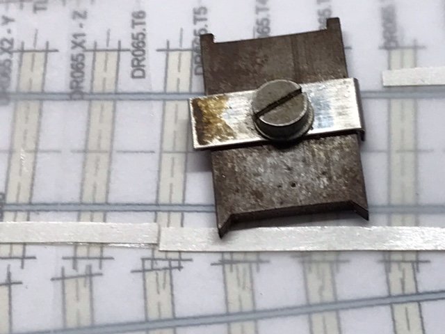
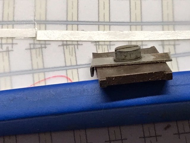
I'm using 1mm thick double sided copper paxolin. Holes drilled 2.5 or 3mm for the hinge bolts to pass through. I countersink these to avoid solder getting too close to the thread ...

Yeovil lose heeled switch (4).jpg


On the underside, I place a 10BA nut held roughly in place with the 10BA bolt, pre-oiled to prevent soldering everything up solid. Apply the merest smidgen of Power Flux paste from a syringe. Tiny amount each side of the nut.
Yeovil lose hinged switch (1).jpg


Apply a minimum of solder to nut and the job is done usually without soldering bolt to nut.

Yeovil lose hinged switch (2).jpg


Once I've two nuts soldered to the underside of the timber I turn it right way up and superglue in position where I've previously drilled two holes right through the baseboard so the bottom ends of the bolts can have track feeds attached to feed the switches themselves. Here one bolt has been screwed all the way down and protrudes below base board for the feed. The other is waiting to be screwed down. I gap the timbers, top and bottom, twice to be on the safe side and test them for shorting, before installing.

Yeovil lose hinged switch (6).jpg


Kind regards
Andrew
 
_______________
message ref: 300
Last edited:

Paul Boyd

Member
Location
Loughborough, UK
That’s a very well timed post, Andrew. I’ve been pondering how best to do this for a 3-way stub turnout, and this will work for me very well indeed. Thanks!
 
_______________
message ref: 301

Andrew Duncan

Member
Thread starter
Location
Reigate
That’s a very well timed post, Andrew. I’ve been pondering how best to do this for a 3-way stub turnout, and this will work for me very well indeed. Thanks!
Hello Paul
I'm glad it helped, and I know that I should know the answer to this question, but what is a stub turnout?
Andrew
 
_______________
message ref: 302

Paul Boyd

Member
Location
Loughborough, UK
I'm glad it helped, and I know that I should know the answer to this question, but what is a stub turnout?
To grab a quick screenshot, it's one of these! The red rails are the loose heel blades which are simply moved to the appropriate exit track. (I've just discovered that you need to click the "View media item" after clicking the picture otherwise it's too fuzzy)

Capture.PNG
 
_______________
message ref: 303

Andrew Duncan

Member
Thread starter
Location
Reigate
and here the most northerly turnout in the station under construction. I tried doing the crossing itself in situ, but it isn't as good as building directly on a copy paper plan, giving them a good wash and brush up in the sink before installing. So I shall go back to my previous method for the last two turnouts. I can't believe that I'm that close to completing turnout construction for the station itself....!

Yoevil north T out (1).jpg


That's it for tonight
Kind regards
Andrew
 

Attachments

  • [Yeovil Brd 6 North  (1).jpg
    [Yeovil Brd 6 North (1).jpg
    734.9 KB · Views: 181
_______________
message ref: 304

Andrew Duncan

Member
Thread starter
Location
Reigate
To grab a quick screenshot, it's one of these! The red rails are the loose heel blades which are simply moved to the appropriate exit track. (I've just discovered that you need to click the "View media item" after clicking the picture otherwise it's too fuzzy)
Hello Paul
Thank you for the explanation. So you'll hinge at the far left-hand end of the red rails I take it? Not sure why I say this but might it be too sharp a deviation? Having written this, I suppose it's the same as my use? Except that with my application I only have to get one rail in good alignment, and the one not in use is out of alignment it but doesn't matter of course. I'm probably concerned needlessly.
Kind regards
Andrew
 
_______________
message ref: 305
Location
Up North
Hi Andrew,
Nice job with the loose heel pivots. I did see the same thing at track making demo a few years back but he used smaller bolts ( can't remember the size ) that were not visible once the rail was soldered on top. He did admit to thinking that maybe a larger size bolt would be more robust in the long run so maybe you have it spot on. I guess the cosmetic chair on top will hide the bolt though ?

I have been doing a few track items today. Batch filing of frogs common crossings and switch rails in code 82 flat bottom rail for some US project I have in mind. I also milled down some copperclad to use in the turnouts as thin copperclad strips are hard to find and expensive if you do.

Rob
 
_______________
message ref: 306

Andrew Duncan

Member
Thread starter
Location
Reigate
Hi Andrew,
Nice job with the loose heel pivots. I did see the same thing at track making demo a few years back but he used smaller bolts ( can't remember the size ) that were not visible once the rail was soldered on top. He did admit to thinking that maybe a larger size bolt would be more robust in the long run so maybe you have it spot on. I guess the cosmetic chair on top will hide the bolt though ?

I have been doing a few track items today. Batch filing of frogs common crossings and switch rails in code 82 flat bottom rail for some US project I have in mind. I also milled down some copperclad to use in the turnouts as thin copperclad strips are hard to find and expensive if you do.

Rob

Hello Rob
Thanks and yes I could use a smaller size of bolt and yes it would be neater, or infact turn down the head a bit which would do the same thing probably, and you know, the perfectionist in me thinks "yes what a good idea". But did I do it? No. I suppose I'm a bit of a bodger as well at heart. When I see \ read the attention to detail that many go to, John(Hayfield) and Tony come to mind, and there are many others, who will go to great lengths to model the track in the correct length panels and make sure that exactly the correct chair is used in the right position in the point work, and I do actually identify quite strongly with that level of commitment. But I am building a largish layout by myself and am trying to create a picture of how the place looked in 1922. The picture is by no means a photograph, it's more like an impressionist painting (trust Monet, Manet at al will forgive me!) and I know that if I'd been unable to get the correct two bolt chairs, then I'd have used 3 bolt instead and actually that wouldn't have worried me too much. Partly because my eyes aren't that good these days and partly because it I'm a broad brush stroke sort of bloke. I'm happily using C&L flexi track and I doubt that's correct for GWR 1920's but it doesn't worry me.

What would concern me though is bullhead rail soldered/attached directly to the sleeper, because that, to my eye, really does show. The elegant rather delicate look of bullhead track makes the most huge difference to the look of the layout I think, and although the rail is only raised a smidgen over half a mil off the sleeper, it matters a lot to me that it's there (the gap).

Writing about this rather gungho, lackadaisical approach on this, a track building forum, is possibly a risky strategy, but I'm not really telling you Rob, or any of you who have observed my antics for the last 7 years, anything you didn't already know. You have always been kind and constructive in your criticism and I've had loads of encouragement, friendship and humour that continues to make it hugely enjoyable.

Well, that was a longer answer than either of us was expecting I'll wager! Does the cosmetic chair cover the bolt head....yes sort of, in a bodgerish sort of way...don't look too close!

Milling copper paxolin. What for exactly and do you have a picture or two..?

Kind regards
Andrew
 
_______________
message ref: 312
Location
Up North
Andrew,
In some situations I like to have thinner than normal sleepers, think of goods yards/overgrown sidings etc, to give the impression that the truck is almost buried in the ground. Using a 'standard' sleeper depth means more work in raising the level of the surrounding levels to get the track to bed down as I wish. No pictures yet but maybe at some point.

I like to use plastikard sleepers cut from sheets - you get a lot per sheet - is the easiest way to approach it and 0.5mm ( 0.020" in old money ) is a good compromise thickness. You can't buy ( unless you know otherwise ? ) PCB in this size strips so last night was about milling down some 1.06mm strips to 0.5mm. I use a small jig that has a plastikard top and strips of 0.4mm plastikard set so they hold the original PCB strips in place under the cutter. It is fairly quick to do once the jig is made and the results are good although the cutting forces mean the strips come out with a pronounced curve. They form back flat by running them through the fingers.

It is similar to the principle of a router table for shaping wood, I was going to have the PCB strips fixed down and move the cutter over them but just feeding the PCB strips under the cutter whilst being guided by the plastikard strips is easier. The sleepers are double sided fibreglass rather than paxolin which I think would be weak in this thickness.

I am with you all the way with your layout. It must seem like work progresses slowly sometime with no end in sight. A little time saved here and there can help you to get though a little quicker. As you know I do so enjoy reading and seeing your progress.

Rob
 
_______________
message ref: 313

Andrew Duncan

Member
Thread starter
Location
Reigate
Andrew,
In some situations I like to have thinner than normal sleepers, think of goods yards/overgrown sidings etc, to give the impression that the truck is almost buried in the ground. Using a 'standard' sleeper depth means more work in raising the level of the surrounding levels to get the track to bed down as I wish. No pictures yet but maybe at some point.

I like to use plastikard sleepers cut from sheets - you get a lot per sheet - is the easiest way to approach it and 0.5mm ( 0.020" in old money ) is a good compromise thickness. You can't buy ( unless you know otherwise ? ) PCB in this size strips so last night was about milling down some 1.06mm strips to 0.5mm. I use a small jig that has a plastikard top and strips of 0.4mm plastikard set so they hold the original PCB strips in place under the cutter. It is fairly quick to do once the jig is made and the results are good although the cutting forces mean the strips come out with a pronounced curve. They form back flat by running them through the fingers.

It is similar to the principle of a router table for shaping wood, I was going to have the PCB strips fixed down and move the cutter over them but just feeding the PCB strips under the cutter whilst being guided by the plastikard strips is easier. The sleepers are double sided fibreglass rather than paxolin which I think would be weak in this thickness.

I am with you all the way with your layout. It must seem like work progresses slowly sometime with no end in sight. A little time saved here and there can help you to get though a little quicker. As you know I do so enjoy reading and seeing your progress.

Rob
Hello Rob
Ah I see now what you want it for. I recall a couple of years ago you and Nigel and one or two others suggested that approach to me for the sidings on Yeovil. I didn’t apply it because I’d already laid a good proportion of them but thought it was a good idea for the very reason you’ve talked of. And in fact I’m still going to have to build up the ground level more because the sleeper depth in the goods areas.

So thanks for the explanation and the photos and the kind comments. All very much appreciated and encouraging.

Would I be pushing my luck in asking for a track plan of the proposed layout?

kind regards
Andrew

PS. Love your vernier gauge, looks expensive and rather swish in its simplicity
 
_______________
message ref: 315

Martin Wynne

Admin
Location
West of the Severn UK
Info
.
Enjoy using Templot?
Thanks.

Please do not send requests for help direct to me via email.

Post your questions on the forum where everyone can see them and add
helpful replies.
PS. Love your vernier gauge, looks expensive and rather swish in its simplicity

To be excessively pedantic for a moment, it is not a Vernier gauge. :)

Any form of caliper gauge tends to be called a "Vernier" but actually that term applies only to calipers which use Vernier graduations for accurate measurement:

vernier_scale.png


The Vernier scale was invented by Pierre Vernier in 1631. The basic idea is that 9 divisions on the main scale are divided into 10 divisions on the sliding scale. You can then estimate tenths of a main division by seeing where there is alignment with the sliding scale:

vernier_scale_ani.gif

CC BY-SA 3.0

More info: https://en.wikipedia.org/wiki/Vernier_scale

What Rob has is called a Dial Caliper. It works by running a small pinion gear along a toothed rack. Much easier to read than a Vernier Caliper, especially in dim light. But having small moving parts it tends to be easily clogged up when working in dusty or swarfy conditions around machine tools. The Vernier Caliper has no moving parts other than the main slider and tends to be indestructible.

Nowadays of course most folks use a Digital Caliper instead, and hope the world supply of batteries never runs out.

Martin.
 
_______________
message ref: 318
Location
Up North
Hi Andrew,
No I don't have any track/layout plans just yet. Watch this space as they say.

The caliper you see is one of these :
1611685551272.png


I think it was around £25.00 but the Ebay sellers don't seem to have any these days. It is marked in 0.01mm graduations which is probably not required for most of the things we are doing - it does correspond to approx 0.0004" in imperial. I also have a metric one that has 2mm per dial revolution on the other workbench which of course reads in 0.02mm increments..

As has been said on here before the issue with digital ones is that they don't properly power off when you press the off button - they just turn the display off. I got frustrated by the number of times I had to scramble around for a battery before I could take a measurement. if you have a digital one and want to know if is does properly power down just see if it remembers the reading after you power it off and back on - if it does then it didn't actually power all the way down.

Rob
 
_______________
message ref: 319

Andrew Duncan

Member
Thread starter
Location
Reigate
To be excessively pedantic for a moment, it is not a Vernier gauge. :)

Any form of caliper gauge tends to be called a "Vernier" but actually that term applies only to calipers which use Vernier graduations for accurate measurement:

View attachment 206

The Vernier scale was invented by Pierre Vernier in 1631. The basic idea is that 9 divisions on the main scale are divided into 10 divisions on the sliding scale. You can then estimate tenths of a main division by seeing where there is alignment with the sliding scale:

View attachment 207
CC BY-SA 3.0

More info: https://en.wikipedia.org/wiki/Vernier_scale

What Rob has is called a Dial Caliper. It works by running a small pinion gear along a toothed rack. Much easier to read than a Vernier Caliper, especially in dim light. But having small moving parts it tends to be easily clogged up when working in dusty or swarfy conditions around machine tools. The Vernier Caliper has no moving parts other than the main slider and tends to be indestructible.

Nowadays of course most folks use a Digital Caliper instead, and hope the world supply of batteries never runs out.

Martin.
Hello Martin
I stand educated! Thank you and thank you for such a clear beautifully illustrated reply. Very clear.
Kind regards
Andrew
 
_______________
message ref: 321

Andrew Duncan

Member
Thread starter
Location
Reigate
Hi Andrew,
No I don't have any track/layout plans just yet. Watch this space as they say.

The caliper you see is one of these :
View attachment 210

I think it was around £25.00 but the Ebay sellers don't seem to have any these days. It is marked in 0.01mm graduations which is probably not required for most of the things we are doing - it does correspond to approx 0.0004" in imperial. I also have a metric one that has 2mm per dial revolution on the other workbench which of course reads in 0.02mm increments..

As has been said on here before the issue with digital ones is that they don't properly power off when you press the off button - they just turn the display off. I got frustrated by the number of times I had to scramble around for a battery before I could take a measurement. if you have a digital one and want to know if is does properly power down just see if it remembers the reading after you power it off and back on - if it does then it didn't actually power all the way down.

Rob
Hello Rob
Shame about the track plan, I'll remind you from time to time if I may? Might be a late "new years" resolution for you....?

Anyway thanks for the explanation as to why my digital ones run their batteries down so quickly. Not showing off you understand, but I've got three, two pretty accurate and one not so, and the two I use with some regularity both run their batteries down within the year certainly. But as long as Martin's scary scenario doesn't come to pass, then I'll be ok...
Andrew
 
_______________
message ref: 322
Top