Templot Club forums powered for Martin Wynne by XenForo :

TEMPLOT 3D PLUG TRACK - To get up to speed with this experimental project click here.   To watch an introductory video click here.   See the User Guide at Bexhill West.

  • The Plug Track functions are experimental and still being developed. Some of the earlier pages of this topic are now out-of-date.

    For an updated overview of this project see this topic.   For some practical modelling aspects of using Plug Track see Building 3D Track.

    The assumption is that you have your own machines on which to experiment, or helpful friends with machines. Please do not send Templot files to commercial laser cutting or 3D printing firms while this project is still experimental, because the results are unpredictable and possibly wasteful.

    Some pages of this and other topics include contributions from members who are creating and posting their own CAD designs for 3D printing and laser-cutting. Do not confuse them with Templot's own exported CAD files. All files derived from Templot are © Martin Wynne.
  • The Plug Track functions are experimental and still being developed.

    For an updated overview of this project see this topic.   For some practical modelling aspects of using Plug Track see Building 3D Track.

    The assumption is that you have your own machines on which to experiment, or helpful friends with machines. Please do not send Templot files to commercial laser cutting or 3D printing firms while this project is still experimental, because the results are unpredictable and possibly wasteful.

    Some pages of this and other topics include contributions from members who are creating and posting their own CAD designs for 3D printing and laser-cutting. Do not confuse them with Templot's own exported CAD files. All files derived from Templot are © Martin Wynne.

Experimental 3D plug track - up to version 244c

Quick reply >
Hi Martin,
Your spot on, we normally change our clocks either a week or two weeks after the UK but we are going in the opposite direction.
IE as you move into BST we are coming out of NZST and visa versa.
Given you feeling much better, which I am glad to here. I will set my alarm and be in attendance. This time I will just listen I promises :)
Cheers
Phil
PS I got some very weird results last night when trying to rotate a tiled map image. It may have some thing do with going out for a meal with my wife, and having a bottle of very good pinot noir, something NZ excels at.
 
_______________
message ref: 6347
Hi Martin,
Your spot on

@Phil G

I'm now totally confused! For your reference the time now in the UK is 12:15 , so you can work out the difference. The Zoom meeting will start in 7 hours 45 minutes from now.

cheers,

Martin.
 
_______________
message ref: 6348
Hi Phil,
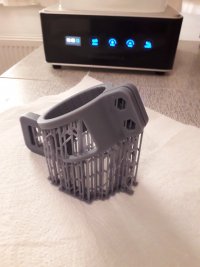
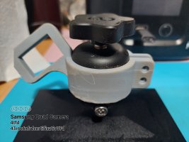
With reference to Mars 3 drip bracket, I found this on thinguverse & printed it in resin:_
20230415_080440.jpg
Took nearly 5 hours, cost £1.37
Tested ok:-
20230415_102202.jpg
The benefit of this design is that it stays clamped to build plate so much easier to slide build plate off and on the printer bracket less faff than themars2 supplied Bracket.
Will post a link later when have laptop o
Steve.
 
_______________
message ref: 6365
Hi Steve,
That looks fantastic.
Was it supposed to be printed on an FDM printer? As I found a file similar to that on Thinguverse, but it was for a FDM machine, even though it was a STL file type. I had not made the connection that a STL designed for FDM could also be made to work on a resin printer.
Cheers
Phil
 
_______________
message ref: 6366
Hi Phil,
I believe it is designed for resin printing, there are 3 files, I downloaded the chitubox project one which already had supports, then opened in chitubox, at first it looks too large but that is just perspective view.
All I did was slice, save & print.
Be patient as it does not look as though it is printing properly, because of the nest if supports it is not easily visible, but it does, after washing I removed supports before curing.
Steve
 
_______________
message ref: 6368
 
_______________
message ref: 6369
Here is the link
https://www.thingiverse.com/thing:3895021

That is for version 5 that I printed, but he has a version 9 as well.

designer is psdesign and he has lots of other thingi's

As i have 2 build plates I am going to print a second one.

removing the supports from around the bolt holes was a bit fiddly but the bracket certainly works, just got to give it a couple of scoosh coats!
Steve
 
_______________
message ref: 6370
Here is the link
https://www.thingiverse.com/thing:3895021

That is for version 5 that I printed, but he has a version 9 as well.

designer is psdesign and he has lots of other thingi's

As i have 2 build plates I am going to print a second one.

removing the supports from around the bolt holes was a bit fiddly but the bracket certainly works, just got to give it a couple of scoosh coats!
Steve
@Steve_Cornford

Hi Steve,

This one:

https://www.thingiverse.com/thing:4430372

seems to a development of that with a slight additional twist in the holder so that one corner of the plate is lower than the other.

cheers,

Martin.
 
_______________
message ref: 6373
Hi Phil,
3895021 is the one I printed, if you read the comments he printed it on a Mars printer, the picture looks like red resin to me.
I just downloaded the 2nd file in list, opened in chitubox , sliced , saved & printed.
Martin has found a slightly different that might be better.
 
_______________
message ref: 6374
_______________
message ref: 6375
Well I am 4 hours 18 mins into printing the v9 drip bracket, only another 1 hour 27 mins to go!

It's the tallest print I have done so far, just hope I have enough IPA to fully immerse it in the wash tank!
 
_______________
message ref: 6380
.
Having messed up badly in 237c I'm trying to get back on track for 238a.

A lot of tickboxes have been removed from here:

dxf_238a.png


and reappeared here:

jaws1_238a.png


I unticked the option above to have an inner gauge jaw on all S1 chairs on this template, or an outer jaw on all S1J joint chairs on this template:

jaws_238a.png

What's the good of that? Well not much, normally those 2 columns would be left all ticked. But the new mechanism recreates the previous option to omit individual chair jaws. That might be useful in some complex formations where you want a short partial template with a blank chair base onto which individual cosmetic jaws can be glued after construction. It's going to be a long time before every possible special chair is directly available within plug track.

I'm hoping get 238a done this week. But this time it won't be released until I have tested it thoroughly!

cheers,

Martin.
 
_______________
message ref: 6382
I'm looking to print off a trial section of the crossover and I would like to try breaking the formation down into say 130 x 130 sections. I think I need to utilise the 'brick' function with joining clips etc. Can anyone point me in the right direction for some basic instructions, scruff vid or post thread?
 
_______________
message ref: 6384
@Terry Downes

Hi Terry,

This topic covers the timbering bricks (7 pages):

https://85a.uk/templot/club/index.php?threads/extracting-a-3d-timbering-brick-from-a-track-plan.295/

The experimental functions changed a lot during the course of that topic, so you need to read all of it to be up to date on them.

These menus on the background shapes dialog contain most of the brick functions:

con_clips.png


But I can't remember ever properly writing it all up, sorry.

If I could just get the turnout chairing finished, I can go back and sort out all this stuff that got left half-finished along the way, and write some proper plug track instructions.

Ask again if anything is unclear. @Paul Boyd is our official bricklaying correspondent. :)

cheers,

Martin.
 
_______________
message ref: 6385
Ask again if anything is unclear. @Paul Boyd is our official bricklaying correspondent. :)
Who, me? :)

It's been a while since I did the bricks, and now that I've changed the gauge I'm going to have to start again but hopefully with the benefit of experience! I never did get to write up my notes properly, but I've attached my scribbles to this post which I hope will be a good reference - it's just as I scribbled it, warts and all. These notes were out of date even as I was writing them (I do believe this whole area might be experimental!). The link posted in the previous message is the one I would have posted as well.

The bricks I made were not intended to be used with plug track so don't have sockets, other than blind "rail head" sockets to act as a guide. I've also attached box files and shape files - I wouldn't normally separate bricks out of the box file but I thought it might make things a little clearer. In the shapes file, the big squares represent my print area. That would be the first thing I sort out, allowing overlap for the clips. It's then a case of making bricks using lots of pretty colours! It's best to use colours from the default palette to make it easier to select by colour, and also to have adjacent bricks in contrasting colours.

Hopefully this will be of some help.

Cheers,
Paul
 

Attachments

  • Notes.txt
    8.2 KB · Views: 72
  • bricks_2023_04_17_2116_26.box
    168.4 KB · Views: 69
  • group_2023_04_17_2117_34.box
    217.9 KB · Views: 63
  • pen_y_bwlch_23_04_17_2121_43.bgs3
    37.9 KB · Views: 67
  • 2022-05-14_17-19-10_PJM0444.HEIC
    1.9 MB · Views: 67
_______________
message ref: 6386
@Paul Boyd

Hi Paul,

Many thanks for taking the trouble to post all that. I had forgotten most of it myself. :)

By the way, have you tried Cura in the latest Windows 11 update? The pop-ups from the Settings Guide now instantly obliterate the setting you are trying to change, making it impossible to change anything. I do wish Microsoft would learn that if it ain't broke, don't fix it. Sigh.

The solution is to go in Cura to Extensions > Settings Guide > Preferences and untick this cryptic box :

cura_settings_guide_popups.png


Don't ask how long it took me to find this. Another chunk of my life I will never get back. Thanks Microsoft :(

You can still get the Settings Guide when you want it by right-clicking on a setting.

cheers,

Martin.
 
_______________
message ref: 6387
Hi, can You advise whether I'm doing something wrong? I have just created a small section of template for test printing of various methods etc. but, the timber which holds the switch soleplate seems to be missing within the Templot screen and does not appear within exported stl file.
1681816404117.png

1681816497421.png

Terry
 
_______________
message ref: 6389
@Terry Downes

Hi Terry,

You are not doing anything wrong. This is another bug in 237c.

Although it can't really be called a bug because the whole thing is an experiment -- stuff gets tried as a proof of concept and not necessarily fully implemented until later, or changed from one version to the next.

In the meantime, you can prevent the problem by not having the soleplate function enabled. Switch it off by setting the combo to blank (right-click on it):

dxf_soleplates.png


Then click rebuild now before exporting. Hopefully that should work.

I will try to make sure it is working again in 238a.

The long and the short of it is that I should not have released 237c when I did. But that would now mean 5 months since the last update, and the longer I leave it the more and more difficult it becomes to release an update, because it needs so much testing and checking.

cheers,

Martin.
 
_______________
message ref: 6390
Thanks Martin, that fixed it.
But, I do wish You would stop apologising and beating yourself up all the time about bugs and being experimental. I for one truly appreciate your knowledge, skills, advise and time with this extremely impressive and thoroughly enjoyable software. And best of all its free!
I actually think You should consider releasing more often and let the users discover the 'bugs' as this would relieve the pressure off Your shoulders.
Stay positive and keep up the great work. Terry
1681820236414.png
 
_______________
message ref: 6391
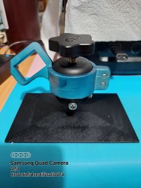
Hi Steve,
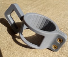
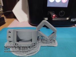
I went with the one Martin highlighted as its angled in both directions,
please see photos note. I have not quite mastered a scooch of paint as you can see
 

Attachments

  • 20230416_210315.jpg
    20230416_210315.jpg
    3.7 MB · Views: 80
  • 20230416_211545.jpg
    20230416_211545.jpg
    4 MB · Views: 71
  • 20230419_002049.jpg
    20230419_002049.jpg
    1.9 MB · Views: 70
  • 20230419_002148.jpg
    20230419_002148.jpg
    2.1 MB · Views: 78
_______________
message ref: 6392
The solution is to go in Cura to Extensions > Settings Guide > Preferences and untick this cryptic box :
Hi Martin

Now you mention it, I did find that but can't remember now how or if I got around it! Thanks for finding that setting though. Programmers who work for these big corporations seem to have to keep churning out code to keep their jobs, but there doesn't seem to be anyone testing it!

Cheers,
Paul
 
_______________
message ref: 6394
@Martin Wynne some time back in the old Templot forum, you very kindly produced a REA specification scissor as I was having issues similar to @Terry Downes. It was also because I had 'assumed' it was a standard 6ft, when in fact (IIRC it's supposed to be 6ft6 or 7ft between the inner rails).

If you still have that on your computer, perhaps it would help Terry? I'm afraid I lost my copy when I replaced the HDD, though I have a PDF of it if that might help.
@Derek @Terry Downes

Hi Derek,

It doesn't ring any memory bells -- but then very little does nowadays. :(

I rarely delete anything, so I should still have it somewhere. Most likely on an old disk drive. I have lots of old drives which are not currently connected to my computer. If you can give me some idea of the date, I can connect one up and see if I can find it.

But whether it will be much help to Terry I'm not sure. Generally it takes less time to start from the beginning than spend ages trying to find and adapt something from years ago.

cheers,

Martin.
 
_______________
message ref: 6396
.
For 238a I have moved several tickbox options from the DXF dialog to this menu, where they are template-specific.

If you untick them, you get an explanation and a chance to change your mind:

no_keys.png


In this case, this option makes it easier to create a scenic pile of chairs stacked outside a p.w. hut for example, or as a wagon load. Such items look a bit daft if they have keys in the chairs. Likewise if they have chair screws in them. We can remove the screw heads, but more work is needed on the screw holes: :)

no_keys1.png


cheers,

Martin.
 
_______________
message ref: 6410
Hi Martin, Just a thought... and I do NOT want to distract You from your imminent release... but, within earlier releases 'I think' you were able to include S1 chairs in the missing crossing/vee areas. Am I imagining this? I know its not prototypical but, I was wondering whether the imminent release would have an option to include/exclude these incorrect chairs or holes or loose jaws as an interim to a full compliment of chairs etc?
1682179080099.png
 
_______________
message ref: 6414
@Terry Downes

Hi Terry,

I could put them back, but I'm mystified why you want them? They are completely unusable in any way to produce usable track. They caused a lot of trouble to folks wasting time and money laser-cutting for them and so forth. I couldn't understand why anyone would do that, and rather late in the day I removed them until I have the proper chairs done.

Essentially Templot puts an S1 chair everywhere until told to put something else. I was dismayed to find that folks couldn't grasp that when I kept saying the whole thing was still experimental, and seeing the obviously wrong chairs in some places.

Just as an example, all the chairs I have done so far have been square-on to the running rail. Those crossing chairs are different -- they are skewed square to the centre-line of the crossing, and not square to either of the rails.

cheers,

Martin.
 
_______________
message ref: 6415
Hi Martin,
I certainly don't want to distract you from working on 238A,
However your comments to Terry really got me thinking, I have always been of the view you were going to have to make chairs Y,X A,B and C, all cosmetic given there is nothing we can do to grip these to the rails. I.e. there is no key to lock the rail web in place.

On the prototypical railway this issue is addressed by bolting the rails directly together, all be it with cast spacer units. and in the case of the A chair the rail tip looks to bolt though the chair and into the timber.

In a somewhat ironic way the old rivet to timber and solder the rail the rivet, thus holding timber and rail directly are a good way of ensuring the crossing vee can't move overtime. Or do have you some very cleaver trick up your sleeve to address this dilemma?
Cheers
Phil,
 

Attachments

  • close up of 1 in 8 vee with chair detail.jpg
    close up of 1 in 8 vee with chair detail.jpg
    229.1 KB · Views: 61
_______________
message ref: 6418
@Phil G

Hi Phil,

I'm working on some ideas for the crossing chairs and spacer blocks. I don't want to say too much until I have properly tested them. I'm hoping that there will be no need to solder the vee point and splice rails together -- as on the Finetrax kits (on 3D-printed bases) for example. Provided they have been accurately filed (in the FDM filing jigs?) it should be possible to install them one at a time -- it's true that if soldered up as a one-piece vee it would be very difficult to fit the plug track chairs.

An obvious issue is that we can't use the prototype dimensions because of the wider than scale flangeway gaps, even in P4.

cheers,

Martin.
 
_______________
message ref: 6419
Hi Martin,
Thanks for the reply,
I thought you my have some ideas up your sleeve. Having had a look at the finescale website, he looks to be doing it, by not being truly prototypical, (which at any scale there has to be a compromise), but instead doing it by creating a constringed path for the vee point and the splice rail to slide into, a bit like a locating jig if you like. Which if you did that would have to cover at least the A and B chairs, maybe even the A, B and C chairs,
A key point to his system however, seems to be that the turnout timbers (made from plastic) are pre spaced and bound to each other (same as PECO points for example) that will add positively to the the required strength of the system will it not?
He also talks about super gluing one or two rails on completion, which presumably would also include the wing and check rails given how short they are. so I am assuming the same for the vee point and slice rails.
Are you also thinking about using super glue?

It would also mean every different crossing angle has to generate a different A B and C combination. Thinking about that's true of any system, but the implication are more so. You would also need to create a jig for every crossing angle Templot generated.
Are you planning to do this by using variables inside the Templot programme? Or will it be more of a case of just calling up the required preformed jig (designed) angle. IE more like a library of know jig angles? if the latter I would be very willing to help with that.
cheers
Phil,
 
_______________
message ref: 6420
It would also mean every different crossing angle has to generate a different A B and C combination. Thinking about that's true of any system, but the implication are more so. You would also need to create a jig for every crossing angle Templot generated.
Are you planning to do this by using variables inside the Templot programme?
@Phil G

Hi Phil,

I'm not sure what you mean there? Every single thing in Templot is generated from variables inside the Templot program. If you design a 1:7.38 V-crossing, that's what plug track will generate the chairs for, and a matching filing jig if you want one.

I am primarily thinking about a solution for FDM printing and CNC milling. Because those are the machines I have here and can test ideas on. How it will work for laser-cutting I'm not so sure, because as far as I know on home machines it is not possible to do even 2.5D work. I confess that I have been rather wrong-footed in the last few months with so much interest in laser-cutting. I assumed originally that FDM printing is so much more user-friendly and affordable than laser-cutting that the majority of plug track users would be going that way. I just don't see a laser cutter in every typical modellers home workshop in the way 3D printing is going, but maybe I'm wrong?

To continue this project I may have to get a laser-cutter myself, but I'm not attracted to the idea. I shall have to find a safe place for it, and build extraction fans and suchlike. A machine which produces clouds of smoke and flames and can blind you if you forget to put the red glasses on is not something I would look forward to working on nowadays. 40 years ago it would have been meat and drink to me, but not now. Also there is the cost of materials to consider, every plywood test print costing money. I have a large box full of scrap test FDM timbering bases. All of which came from a couple of still unfinished reels of filament. How much they would have cost if made from sheets of plywood I don't know, but I know it wouldn't be cheap.

It's just not possible to progress this project without making test prints myself and getting the results immediately. Trying to develop ideas if you have to send tests off to someone else, laboriously trying to explain exactly what you want, waiting ages for the results, and paying for them, is not a cheap fun hobby -- it's too much like working life.

cheers,

Martin.
 
_______________
message ref: 6422
Martin this is great - I am going to print off some chairs this morning on my anycubic....is there an STL for a test Sleeper Section. Appologies in advance if I am missing the obvious.
 
_______________
message ref: 6423
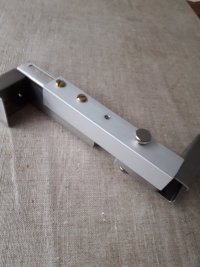
Hi Phil, hopefully you have had time to test the 3D printed drip bracket for your Mars printer.
During the zoom meeting I think you also mentioned the volume of IPA you were getting through.

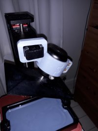
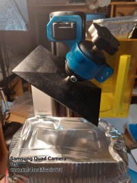
To reduce the amount required to cover the build plate in the Mercury wash, o added an extension to the metal bracket so that the build plate can sit lower in the wash so that I can get away with only 1 litre .
20230423_092447.jpg
It is made from a piece of 20mm by 20mm aluminium angle about 12 cm long, with several holes drilled to allow a couple of M4 nuts & bolts to join the two original parts of the bracket.
Steve
 
_______________
message ref: 6424
Back
Top