Templot Club forums powered for Martin Wynne by XenForo :

TEMPLOT 3D PLUG TRACK - To get up to speed with this experimental project click here.   To watch an introductory video click here.   See the User Guide at Bexhill West.

  • The Plug Track functions are experimental and still being developed. Some of the earlier pages of this topic are now out-of-date.

    For an updated overview of this project see this topic.   For some practical modelling aspects of using Plug Track see Building 3D Track.

    The assumption is that you have your own machines on which to experiment, or helpful friends with machines. Please do not send Templot files to commercial laser cutting or 3D printing firms while this project is still experimental, because the results are unpredictable and possibly wasteful.

    Some pages of this and other topics include contributions from members who are creating and posting their own CAD designs for 3D printing and laser-cutting. Do not confuse them with Templot's own exported CAD files. All files derived from Templot are © Martin Wynne.
  • The Plug Track functions are experimental and still being developed.

    For an updated overview of this project see this topic.   For some practical modelling aspects of using Plug Track see Building 3D Track.

    The assumption is that you have your own machines on which to experiment, or helpful friends with machines. Please do not send Templot files to commercial laser cutting or 3D printing firms while this project is still experimental, because the results are unpredictable and possibly wasteful.

    Some pages of this and other topics include contributions from members who are creating and posting their own CAD designs for 3D printing and laser-cutting. Do not confuse them with Templot's own exported CAD files. All files derived from Templot are © Martin Wynne.

Experimental 3D plug track - up to version 244c

Quick reply >
Hi Martin,

It's not often that you can't knock a key in, and end up with more than a couple of inches or so, sticking out, it has been unknown to knock a key straight through, in which case we hope that a spring key will do the job. Obviously not an option before spring keys became available.
@Phil O

Thanks Phil.

But note that the 2.5" projection mentioned above is the maximum. Templot randomises the amount projecting up to that limit, so that the majority of keys will actually be less than that. Some a lot less.

That's why the software picked up only a few of them needing additional supports. With a reduced maximum it will be a lot fewer, and hopefully none. But if there are any, it can be prevented by reducing the maximum limit further. Every setting can be changed by the user in Templot. Apart from the ones which can't. :)

In the larger scales it might be necessary to allow the supports, and break them off each chair before use. In which case you might just as well leave a longer projection anyway. Or I might be able to modify the bottom edge of the key so that the projecting part will print without needing supports. There is so much still to try and do in this project. I wonder if anyone has noticed that already the keys on the loose jaws differ from those on the fixed slide-on chairs.

cheers,

Martin.
 
_______________
message ref: 6474
Bit of work to do on printer settings to get the chairs to be a nice snug fit......also I need to try and set the custom settings for the S Scale society prefered code 87 rail. I chose the scale profile and it is too tight.....but these are things I can play with.....great system!

Screenshot 2023-04-25 203719.png
 
_______________
message ref: 6475
@Michael Woods

Hi Michael,

I can't be sure from your photo, but your chairs seem to have the rail seat missing (the red component here):

s1_cad.png

The seat supports the underside of the rail. Without it, the rail will be hanging in fresh air on the jaws and the key, and you won't be able to firm the chairs into the sockets. The settings are on the DXF dialog. However, it is all change in update 238a which I hope to have on the server this week, maybe tomorrow.

So it will just be confusing if I explain any more now.

I should have explained that model rail section never matches the prototype exactly, the web thickness is almost always over-scale. You could start by increasing that.

cheers,

Martin.
 
_______________
message ref: 6476
_______________
message ref: 6479
@Phil G

I'm hoping to release 238a today in time for the Zoom meeting tonight.

It's going to be a close shave because I have other things on the go today. But if I don't make it there will be no point in talking about plug track in the Zoom meeting today because there are a lot of changes coming in 238a to fix the pig's ear I made of 237c.

Phil, I'm going to take your advice and throw 238a out of the door as-is, for everyone else to find the bugs. :) I'm sure there are some, but I just don't have time at present to test everything exhaustively myself, and until it is out of the door I can't get on with the crossing chairs.

cheers,

Martin.
 
_______________
message ref: 6481
.
Program update 238a is now on the server.

Restart Templot to update.

Martin.
 
_______________
message ref: 6483
_______________
message ref: 6490
@Terry Downes

Hi Terry,

In the Zoom meeting you wanted the wrong chairs to run through the crossing?

You can do that if you change to the all L1 bridge chairs option:

terry_all_bridge2.png


terry_all_bridge1.png


That option is of course intended only for plain track on waybeams, and it's a bug that it works on a turnout and plain sleepers. Or at least it is at present, it wouldn't be a bug if I make it apply only to replacing S1 and S1J chairs, and only on timbers, through a turnout. Not that I can see any reason why anyone would want such a thing, but they might do.
edit: I have seen pointwork using bridge chairs on waybeams adjacent to a water column, so that drains can be provided between the rails for any overflows. Would be an interesting detail to model.

You can do the same thing using the all SC fictional chairs option, but in that case another bug means you don't get any chair jaws, just the chair bases. But you do get longer sockets more suited to the location.

To make practical use of this you would need to create several partial templates, with timbers shortened so that the sockets don't conflict:

terry_all_bridge3.png


For some reason the check rail chairs aren't being replaced, so that's another bug.

These are the sort of bugs I would have found if I had delayed 238a to do more testing. No doubt there are more.

I can't see any practical use for the above, even the sockets will conflict through the crossing and not draw properly into the timbers, but it's what you asked for. :)

cheers,

Martin.
 
_______________
message ref: 6494
.
There was some talk in the Zoom meeting about cutting the chairs from the raft. Here is the diagram I mentioned (I was referring to the raft as a "skate" at the time I posted it):

index.php


index.php


The edge rebate along the underside of the raft is intended to aid prising it from the build plate.

It's very advisable to have only 2 rows of chairs on a raft. On the left above you can see where I have broken a raft in half in order to get at the middle chairs with the cutters. Multiple rafts can easily be cloned on the printer build plate, using the slicer software.

If the plug doesn't cut cleanly from the support pyramid, the chair can be dropped into a loose-fitting socket on a spare timber, and given a rub across the underside with a file, to ensure it won't bottom in its destination socket before it is fully home.

cheers,

Martin.
 
_______________
message ref: 6500
In that diagram the rebate at the top of the pyramid looks quite pronounce, very similar to the base plate overhang above the plug. When I printed some Check chairs it did not seem so pronounced. Is it possible that the default parameter has the wrong value?
 
_______________
message ref: 6501
In that diagram the rebate at the top of the pyramid looks quite pronounce, very similar to the base plate overhang above the plug. When I printed some Check chairs it did not seem so pronounced. Is it possible that the default parameter has the wrong value?
@Steve_Cornford

Hi Steve,

Here are the current sizes, for the 3P (switch) and CCL/CCR (check rail) chairs:
pyramid_top_width.png


I made the pyramid top wider than before in order to accommodate the slot for the loose pin, in the situation where the slot is skewed in the chair, and may be very significantly skewed. If it isn't much skewed, or you are not using loose jaws, you can change the settings:

pyramid_top_width3.png


and/or make the plug deeper and wider at the bottom by being less tapered:

pyramid_top_width4.png


which results in this:

pyramid_top_width2.png


pyramid_top_width1.png


That's the default check rail end chair, and the slot looks to be fine with the gentle 1:18 REA flare angle. But the numbers don't quite add up, so I need to check what the mesh fixer makes of it. Probably it's fine.

Another option (so many things to try before we arrive at the final design!) would be to make the pyramid top wider than the plug, and use the cutters the other way up? We could then make the pyramid a lot shorter (lower) to avoid wasting so much resin. But there might be an adverse effect on wash flow.

I'm sorry I didn't explain all this when you asked about it in the Zoom meeting. It's getting a bit beyond me to explain everything, and I don't know what to do about it. :(

cheers,

Martin.
 
_______________
message ref: 6503
Hi Martin,
Thanks for explaining this in detail, and especially for the suggeston of having a loose fitting timber base as a filing jig.
Snipping the chairs off the raft (or would you prefer us to call it a skate?) is not an exact science so there will always be the odd chair that needs the bottom of the plug tidying up.
I would not worry too much about resin consumption, as we seem to be able to get 120 S1 chairs on the build plate of the Mars for a resin cost of 37p.
As long as you are happy to let me dabble & try this out I will continue to play experiment.
ps Hope you manage to get to a bluebell wood before they disappear.for the year.
 
_______________
message ref: 6504
Hi Martin,
Just a quick question,
when you go into the part of the program that allows pyramid dimension adjustment, as you have shown above.
Does that then act the same on all the chairs that have been selected in the new chair options? IE if I understood the zoom meeting correctly, (which by the way was very informative, thanks for posting it so soon) we now have the option by the radio buttons, to select which chairs and what type of jaws we can export out of Templot, thus creating a mixed raft of chairs for exact requirements.
Cheers
Phil,
PS please can we still keep calling it a (raft) :) As I have my head around that.
 
_______________
message ref: 6505
or would you prefer us to call it a skate?
@Steve_Cornford

I'm happy with raft. I called it a skate because I saw that term being used on several 3D printing web sites. It's not a good term because it suggests something which slides about -- which is the opposite of what we want. A raft can float about too, but presumably can be moored. The most obvious term is slab, but we are already using that for rectangles within the timbering bricks.

Words, words -- it has always been the words. Within the code a stored template is still called a keep, and the storage box is still called the keeps box. I was persuaded to change the public name by Brian Lewis of C&L, and have always regretted it. Templot itself was very nearly changed to Platelayer, logo created, but I'm glad now that I never quite got round to doing it. It's important nowadays to use a word which isn't in the dictionary, so that you get top of the Google results without even trying. :)

cheers,

Martin.
 
_______________
message ref: 6506
Hi Martin,
Just a quick question,
when you go into the part of the program that allows pyramid dimension adjustment, as you have shown above.
Does that then act the same on all the chairs that have been selected in the new chair options? IE if I understood the zoom meeting correctly, (which by the way was very informative, thanks for posting it so soon) we now have the option by the radio buttons, to select which chairs and what type of jaws we can export out of Templot, thus creating a mixed raft of chairs for exact requirements.
Cheers
Phil,
PS please can we still keep calling it a (raft) :) As I have my head around that.
@Phil G

Hi Phil,

At present those settings are global across the entire exported file. Not all of them are even included in the custom settings file. I just can't do everything at once. :)

It's my intention that eventually everything will be template-specific and applicable to individual chairs, as now done in 238a for some* of the chair jaws. I didn't start off doing it that way because I didn't actually know what settings would be needed -- and I still don't. Adding extra settings into the BOX file is far more work than temporary global settings. I put that list of buttons on the DXF dialog primarily for my own use to find out what the default values should be.

At some stage we are going to need a new file format, for the custom chairs, which might then include some of these settings. But that's a lot of work, so will have to wait for now.

By now I should be working on the crossing chairs. But yet again I have been distracted -- I'm currently working on the pyramid tops to make the width dynamic, and only widened for chairs where it needs to be for skewed pin slots.

*I forgot to include the SC fictional chairs in the list. Consequently they are now without any jaws at all. :(

cheers,

Martin.
 
_______________
message ref: 6507
Martin - Firstly thank you for the zoom call.

I have now loaded the new version of Templot

Thank you

Quick question at the risk of making myself look very foolish. When I export the 3D sleeper file, here my file name is black track as I want to print in black, I am getting the following error. It appears a colon is being inserted after the .STL.

Screenshot (201).png
 
_______________
message ref: 6512
@Michael Woods

Hi Michael,

Good to see you at the Zoom meeting. :)

That's very odd. The colon isn't being added by Templot, I just exported an STL to check:

stl_file_name.png


So it must be something in your Meshmixer program. Presumably you can edit the file name in the File > Open dialog?

Maybe when you edited the file name to black_track you accidentally added a colon?

Have you tried using the online mesh fixer service instead:

https://www.formware.co/onlinestlrepair

cheers,

Martin.
 
_______________
message ref: 6513
It's my intention that eventually everything will be template-specific and applicable to individual chairs, as now done in 238a for some* of the chair jaws. I didn't start off doing it that way because I didn't actually know what settings would be needed -- and I still don't. Adding extra settings into the BOX file is far more work than temporary global settings. I put that list of buttons on the DXF dialog primarily for my own use to find out what the default values should be.

I've looked back through all my plug track posts and I think perhaps there is something I have never properly explained.

I keep saying that the project is an experiment. What that means is that the present user interface for plug track is a complete kludge from start to finish. I simply tied everything needed to conduct the experiment onto the existing dialogs with string, as a temporary expedient to avoid needing to write everything from scratch. For example I re-used the existing background shapes as a quick means of adding some non-track components into the 3D export. I put all those extra buttons and tick boxes on the existing 2D DXF dialog (which I hadn't looked at for years) as a convenient place to put them for now, so that I can change the settings and see what happens.

It's not intended to stay that way in the finish. Or at least, it wasn't my intention originally and it still isn't if I keep going long enough. The idea is that when the experiment is over, when we know what works and what doesn't and what is wanted, a completely new set of dialogs and file formats will be created to support the new 3D functions. The existing background shapes and DXF dialog can then revert to what they were before plug track.

I've made a start on that with the new chairing options dialog in 238a, but I've done it in isolation from anything else, and I'm fairly sure it will need some changes before we are finished.

It's dawned on me that a lot of folks just haven't grasped all this. That the current plug track stuff has been bodged into Templot simply as a temporary means to find out if it works. You are not seeing the final implementation of this function, so there is no point in learning where everything is, or expecting it to be in the same place twice running. Or even to exist in the end.

The thing I need to know most is -- does it actually work? Are you able to make track which is fit to be used on a model railway and which trains will run on? The exact details of which button does what and why can come later when we know if the whole thing is worth doing in the first place.

cheers,

Martin.
 
_______________
message ref: 6514
@Michael Woods

Hi Michael,

Good to see you at the Zoom meeting. :)

That's very odd. The colon isn't being added by Templot, I just exported an STL to check:

View attachment 5608

So it must be something in your Meshmixer program. Presumably you can edit the file name in the File > Open dialog?

Maybe when you edited the file name to black_track you accidentally added a colon?

Have you tried using the online mesh fixer service instead:

https://www.formware.co/onlinestlrepair

cheers,

Martin.
Tried everything - including the online formware - I must be doing something silly.....tried to see if I can attach it here....now called usual market_square etc.....
 

Attachments

  • market_square_23_04_29_1324_15.stl
    31 bytes · Views: 64
  • Screenshot (204).png
    Screenshot (204).png
    289.2 KB · Views: 60
_______________
message ref: 6515
@Michael Woods

Hi Michael,

Your STL file is empty. There is nothing in it.

I have just tried creating several STL files and it all seems to be working ok.

Please can you post here your BOX file and a screenshot of the DXF/STL dialog showing the settings you are using. Thanks.

Anyone else seeing empty STL files?

cheers,

Martin.
 
_______________
message ref: 6516
@Michael Woods

Hi Michael,

I have managed to create an empty STL identical yours by selecting the timbering brick only option on the DXF dialog without having previously marked any templates as brick templates. Does that ring any bells?

It's a bug, in the sense that I should have caught it with an error message. I will fix it in the next update.

cheers,

Martin.
 
_______________
message ref: 6518
If you find you need to have 3 dimensional capacity at the vee, I am thinking/hoping that's where the router option comes into play.
just an other idea to throw into the mix.
@Phil G

I'm going to start with individual X, A and B chairs, and add the spacer blocks to them. These should fit in the standard sockets, so won't need anything extra cut into the timbers. However, it's going to be difficult to bash fit them without damage, they may need a spot of superglue in a looser-fitting socket. The slicer might want to add extra supports to the spacer blocks. All very experimental.

So far the chairs have been stylised geometrical designs, but mostly I have managed to follow the REA dimensions quite closely.

For most of the crossing chairs I am going to have to play fast and loose with the REA designs to some extent. Not least of course because our flangeway gaps are significantly over-scale (even in P4). But also for other reasons. At present all the existing chairs are rectangular with radiused corners. The corner radius can be easily changed, but having more than 4 sides on a chair would involve a very significant re-write of much of the existing code. That's doable in the long term, but for now I am going to fudge my way round it. Some of the crossing chairs are 8" wide rectangles, so that's no problem. But others are octagonal, with a middle section 10.5" wide or more. In the short term I am going to represent those as 9" wide rectangular chairs.

Also some of the vee chairs are inside-keyed. That might work in P4, S7, but in 00/EM the wheel flanges are likely to clonk the top of the chair jaw. For those chairs therefore plug track will be missing the keys -- they could be added later cosmetically in the larger scales. It also means having a loose gauging jaw, rather than a loose outer jaw. That's sub-optimal, but there is no way to fit 2 loose jaws between the vee rails.

The majority of folks will likely not even notice these discrepancies. I mention all this now to pre-empt the messages from those who do notice them, telling me I have got it all wrong. :)

And because I may never remember to mention it again.

cheers,

Martin.
 
_______________
message ref: 6523
Sorry - still struggling with the empty file error (user). Yesterday I successfully printed some chairs. This morning I want back to change the settings of the custom chairs and now I have the empty file error. Attached is the box file and screen shots. Any thoughts?
 

Attachments

  • sunday 2.box
    57.7 KB · Views: 64
  • Screenshot 2023-04-30 093038.png
    Screenshot 2023-04-30 093038.png
    28.7 KB · Views: 69
  • Screenshot (210).png
    Screenshot (210).png
    424.2 KB · Views: 65
_______________
message ref: 6525
@Michael Woods

Hi Michael,

Do not click the timbering brick option unless you have set up the brick templates (which you most likely haven't):

michael_dxf.png


If you are printing chairs for a single test template, just leave it on the all background templates default setting for now.

I can't write a full explanation now, sorry. See the topic on extracting timbering bricks for more. You don't need that just to print some test pieces.

cheers,

Martin.
 
_______________
message ref: 6526
Try having all 3 tick boxes in the 3D pop-up window ticked when you store the control template, so that when you list the box contents, the templates that you are trying h to export are marked with the correct brick colour
 
_______________
message ref: 6527
Hi Martin - I have been trying to use the custom rail setting and regardless of the settings the STL does not seem to change.....once again this is probably something I am doing wrong. Any thoughts on what I could be doing wrong?
 
_______________
message ref: 6533
@Michael Woods

Hi Michael,

It seems to be working ok here.

1. make sure you have set your S scale before you do anything else. Never attempt to do anything in Templot until you have set your model scale.

2. Do not use the settings at real > rails. They are for 2-D paper templates.

3. click these buttons to set your 3-D rail dimensions:

silly_rail_custom.png


Make sure the custom radio button is selected before exporting.

It seems to be working ok in both DXF and STL -- I entered some silly dimensions to check:

silly_rail.png


silly_rail_stl.png


What dimensions are you using?

cheers,

Martin.
 
_______________
message ref: 6535
.
Following the discussion in the Zoom meeting I have now added the missing reset button.

Also some coloured markers to show which button was clicked last:

reset_both.png


p.s. the markers stay on, even if you subsequently change some of the settings manually.

Will be in the next update.

cheers,

Martin.
 
_______________
message ref: 6536
@Michael Woods

Hi Michael,

It seems to be working ok here.

1. make sure you have set your S scale before you do anything else. Never attempt to do anything in Templot until you have set your model scale.

2. Do not use the settings at real > rails. They are for 2-D paper templates.

3. click these buttons to set your 3-D rail dimensions:

View attachment 5627

Make sure the custom radio button is selected before exporting.

It seems to be working ok in both DXF and STL -- I entered some silly dimensions to check:

View attachment 5629

View attachment 5628

What dimensions are you using?

cheers,

Martin.
Had real rails sellected.....good news is that the chairs fit the sleepers nicely now.....just spin up another chair print
 
_______________
message ref: 6537
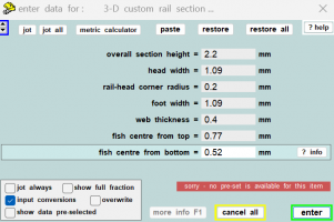
This is the profile that I am trying to use....I have taken the instruction from previous post questions and answsers. But when I try this config and create an STL I cannot repair either in formware or other 3D print repair tools....have I missunderstood and requesting something that is geometrically impossible?

S Scale profile.png
 
_______________
message ref: 6540
Back
Top