would like to shorten it a bit (it is about 3.5 m in 4mm, 3 m would be great), and two methods come to my mind:
1- scale the background in the x direction only (but this will reduce the buildings, and, of course, will modify the turnouts shape)
2- cut and remove a section from the centre
Is one of these methods best? there are other methods? and how can I apply it in Templot?
@Carlos
Hi Carlos,
Welcome to Templot Club.
")
There are several ways to make a track plan from a map fit the available model space -- only you will know which suits your model best.
3. a popular way is to curve a long narrow map so that it fits into or across the corner of the railway room. Templot has a function to
wrap a map image along a curve for that purpose:
Here is a tutorial on how to do it:
https://85a.uk/templot/companion/wrap_picture_shape_to_curve.php
1. your first method, to shrink the image lengthwise only, is the easiest to do in Templot.
modify shape > change dimensions... and change only the X dimensions. Or use the
corner 1 and
corner 2 mouse actions. The image is always stretched to fit the picture shape rectangle which contains it.
The disadvantage there is that the turnout sizes and angles will change, buildings will be distorted, platform lengths will be reduced, etc. Also circular curves will become elliptical, although with typical prototype track radii probably not by enough to be a problem in the model. But elliptical turntables are problematic.
2. on balance I would go for your second method, to trim section(s) out of the map. This preserves the sizes and relative positions of pointwork formations, buildings, bridges, platforms, etc. It does mean that the capacity of loops or sidings may be reduced. It is also more work to do than a simple stretch.
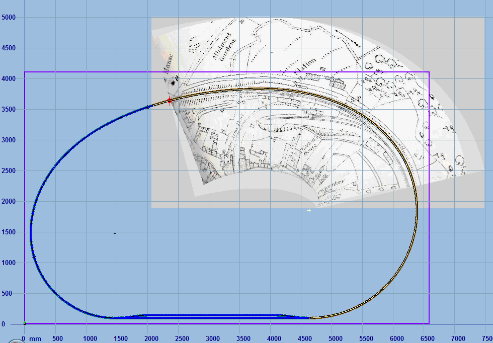
Here I have done that on the Earith Bridge map, reducing the overall length to 3000mm:
The BGS3 file for this is attached below.
As you can see the Signal Box has got lost in the process, and would need to be reinstated somewhere in the middle. Also the length of the loop line is reduced, but still adequate to shunt the sidings. The sections at each end are unchanged from the original.
The running line is curved, so there is a need to calculate the angular offset caused by removing a section of it. To do this I first placed a dummy template on the original map, to find the ruling radius, which was 12000mm (at 4mm/ft) in round figures.
You wanted to remove 500mm from the length, so the angle turned along the removed section would be 500 / 12000 radians x 180 / Pi =
2.39 degrees. This is the angular difference needed between the two end sections of the map in order to re-align the curve after 500mm has been removed from between them.
Here I have made two copies of the map and used the
twist function to get them to a convenient screen alignment. The first one was twisted by
40 degrees. The second one was twisted by
42.39 degrees, so that there is a difference of
2.39 degrees between them.
I then used the
crop/combine function on each of them, arbitrarily using the right-side of the signal box as the split line. Then using the
shift functions I overlaid them with a 500mm overlap:
Then optionally
crop/combine again to produce a single picture shape, as the first screenshot above. Here below is the file for it (4mm/ft).
More about the
crop/combine function:
https://85a.uk/templot/companion/crop_combine.php
cheers,
Martin.
 Search