Search
- Location
- Glasgow
Hi Martin
I don't know whether this is a fault or something I'm not understanding or doing right.
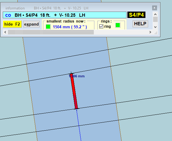
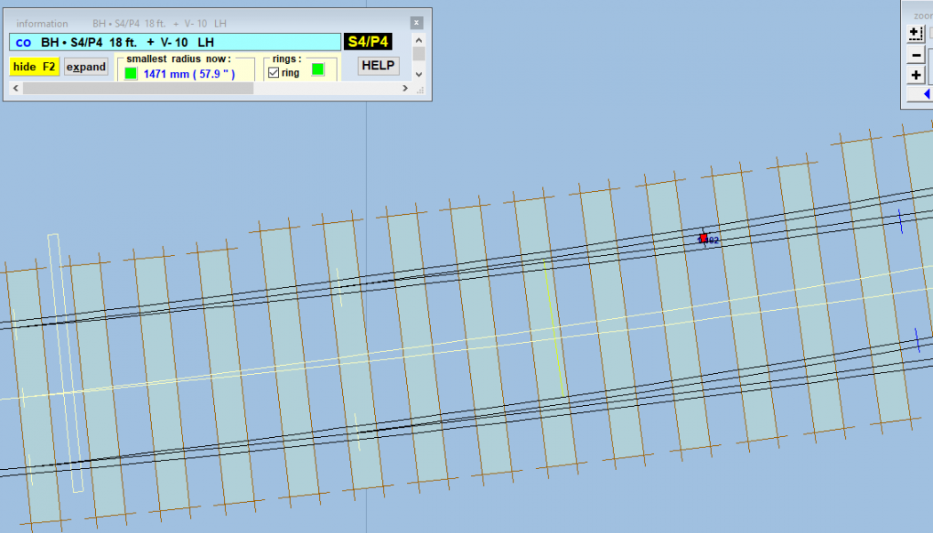
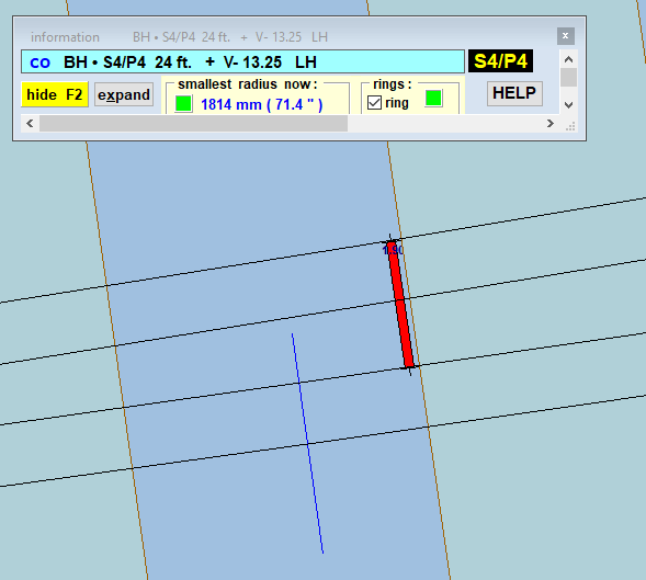
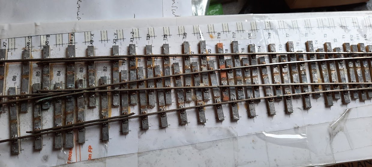
I have made a track plan for Garlieston station with straight heel switches, for our club. One of the members is making the one on the left. It is an 18ft switch but on the template apparently measures 120mm from blade tip to joint, and is after 14 sleepers. The planing length is the expected 44mm he says.
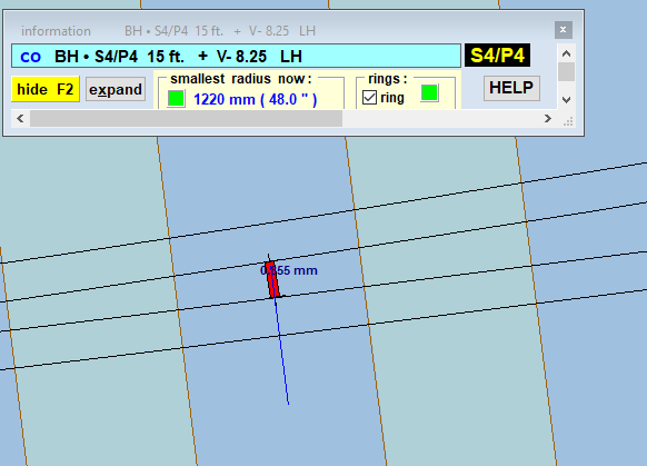
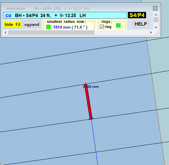
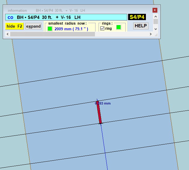
Playing with the F5 function the joint is only 8 sleepers after the tips on a 15ft switch. On a 24ft switch the joint is in the same place as the 18ft, after the 14th sleeper. A 30ft switch takes the joint one sleeper further.
I've downloaded the latest version of Templot but this file was made in June.
I am sorry to bother you as I expect the obvious thing to do is for him to measure 72mm from the tips and make the joint there. But I thought I should ask as if there is a flaw you'd want to know.
All best
Julian
I don't know whether this is a fault or something I'm not understanding or doing right.
I have made a track plan for Garlieston station with straight heel switches, for our club. One of the members is making the one on the left. It is an 18ft switch but on the template apparently measures 120mm from blade tip to joint, and is after 14 sleepers. The planing length is the expected 44mm he says.
Playing with the F5 function the joint is only 8 sleepers after the tips on a 15ft switch. On a 24ft switch the joint is in the same place as the 18ft, after the 14th sleeper. A 30ft switch takes the joint one sleeper further.
I've downloaded the latest version of Templot but this file was made in June.
I am sorry to bother you as I expect the obvious thing to do is for him to measure 72mm from the tips and make the joint there. But I thought I should ask as if there is a flaw you'd want to know.
All best
Julian
Attachments
message ref: 2650