Templot Club forums powered for Martin Wynne by XenForo :

TEMPLOT 3D PLUG TRACK - To get up to speed with this experimental project click here.   To watch an introductory video click here.   See the User Guide at Bexhill West.

  • The Plug Track functions are experimental and still being developed. Some of the earlier pages of this topic are now out-of-date.

    For an updated overview of this project see this topic.   For some practical modelling aspects of using Plug Track see Building 3D Track.

    The assumption is that you have your own machines on which to experiment, or helpful friends with machines. Please do not send Templot files to commercial laser cutting or 3D printing firms while this project is still experimental, because the results are unpredictable and possibly wasteful.

    Some pages of this and other topics include contributions from members who are creating and posting their own CAD designs for 3D printing and laser-cutting. Do not confuse them with Templot's own exported CAD files. All files derived from Templot are © Martin Wynne.
  • The Plug Track functions are experimental and still being developed.

    For an updated overview of this project see this topic.   For some practical modelling aspects of using Plug Track see Building 3D Track.

    The assumption is that you have your own machines on which to experiment, or helpful friends with machines. Please do not send Templot files to commercial laser cutting or 3D printing firms while this project is still experimental, because the results are unpredictable and possibly wasteful.

    Some pages of this and other topics include contributions from members who are creating and posting their own CAD designs for 3D printing and laser-cutting. Do not confuse them with Templot's own exported CAD files. All files derived from Templot are © Martin Wynne.

Placement of rail joints in turnouts

Quick reply >

bordercollie

Member
Location
Australia
Hi

I see that new website is up and running.

I have a query in relation to the placement of rail joints in turnouts and other track formations. I realise from an answer in a previous thread that lengths of rail were produced so as to reduce or eliminate short lengths that could not be utilised elsewhere. However are there any places where a joint can not be placed, other than the join would need to be between two timbers? In my case using 44'6" (178mm) rail lengths a V of 1:7 would roughly work out at 204 mm in 4mm scale. Therefore, I would assume that all else being equal the track builders would try and use two lenghts of approx. 25' (102mm). Is my thinking correct?
 
_______________
message ref: 291
In my case using 44'6" (178mm) rail lengths a V of 1:7 would roughly work out at 204 mm in 4mm scale

Hi,

Sorry you have lost me. Which rail are you referring to? Please attach a BOX file or screenshot showing where you are measuring the 204mm.

cheers,

Martin.
 
_______________
message ref: 292
Hi

I was only using it as an example with rough measurements. What I need to know is whether are any rules as to where joints may or not be made in the stock rails of turnouts.

Regards
 
_______________
message ref: 293
Hi,

I don't know of any specific rules.

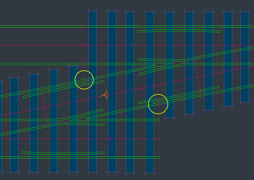
For example the LNER had 2 designs of C-10 turnout. One is jointed in the stock rails for easier transport to site in prefabricated sections. See the extra joints in all 4 rails, in addition to the usual joints at the switch heel. Note also that this is a pre-REA design for the timber spacings at the V-crossing (original NER design).

Where there are joints the adjacent timbers are closed up, and often the chairs adjacent to the joint are the heavier S1J joint chairs. See:

lner_jointed_c10.png

See also this topic:

https://85a.uk/templot/club/index.php?threads/rail-breaks-in-a-crossing.33/

2_091654_040000000.png


2_080826_590000000.png


cheers,

Martin.
 
_______________
message ref: 294
Last edited:
Thanks Martin
I have had another look at the David Smith book. He has some diagrams that show joints in the stock rails at the second timber past the heel in the direction of the V. I don't know if these were just a generic diagrams or this was a rule/ usual practise for GWR turnouts. I think if I use this position I won't be to far from usual practise. Later in the book he also says that GWR didn't worry to much about putting the joints where the timbers ended and the sleepers started. So I think that as far as possible that the track builders would have placed joints that minimised wastage of rail, as you previously told me on a previous thread.
 
_______________
message ref: 307
I have had another look at the David Smith book. He has some diagrams that show joints in the stock rails at the second timber past the heel in the direction of the V. I don't know if these were just a generic diagrams or this was a rule/ usual practise for GWR turnouts. I think if I use this position I won't be to far from usual practise. Later in the book he also says that GWR didn't worry to much about putting the joints where the timbers ended and the sleepers started.
Hi,

PLEASE post a screenshot or diagram showing which part of a turnout you are referring to. Are we talking about switches or V-crossings? This is the first time you have mentioned the GWR, the diagram I posted was for the LNER. Also you haven't quoted your track gauge, 00/EM/P4.

There is always a joint in the stock rail at the heel of the switch. See in David Smith's book the tables on pages 139 and 140 showing the GWR lengths of stock rail manufactured as part of a switch for each size. And the diagram on page 30. Those rail joints are marked on the Templot templates.

The joints in the stock rails at the V-crossing depend on the layout of the connected tracks or other pointwork. See for example the drawing of a crossover on page 86. Note that the GWR had a rule that no length of running rail should be shorter than 15ft or spanning fewer that 6 sleepers or timbers, although it's likely to have been broken in places by sheer necessity.

Sorry, I don't think I can say any more until you post a diagram -- I still don't understand your previous reference to 204mm.

cheers,

Martin.
 
_______________
message ref: 308
p.s. The default vee rail lengths on the templates are for REA V-crossings.

To create a GWR V-crossing you need to change the settings at real > V-crossing options > customize V-crossing > menu items (and also do some timber shoving).

To determine the lengths of closure rails you need to first set either regular or generic/curviform V-crossings. The lengths can't be strictly to scale unless you change to CLM angles and also use an exact scale track gauge such as P4.

For REA I previously mentioned S1J joint chairs. As far as I can tell the GWR used these only on BS-95R rail. I can't find any joint chairs for GWR 00 rail, or joint chairs used within GWR pointwork.

Martin.
 
_______________
message ref: 309
Martin

What dates were BS-95R rail used/introduced please
Hi John,

The BS-95 section was revised to BS-95R in June1922. Of course it took a long time for all existing track to be renewed with the slightly modified new section.

If you are asking about the GWR, the history of rail sections on the GWR is complex -- it is all written up in David Smith's book.

Briefly, prior to the 1920s the GWR used their own "00" rail section (so called because introduced in 1900). As far as I know there were no special joint chairs for this rail. The track panel length was 44ft-6in.

For plain track, the GWR officially adopted the BS-95R section from the 1920s. They designed a new series of 2-bolt chairs for it, including the heavier joint chairs. In practice however, they continued to use the heavier 00 section rail for many years in situations of heavy traffic or corrosion.

For pointwork in main line junctions and complex formations in station throats, etc., they continued to use the heavier 00 section until nationalisation in 1948, and by BR(W) beyond. With BS-95R for lesser pointwork in new work. But most renewals are obviously in areas of heavy traffic, so the 00 rail would in practice be used for the majority of GWR pointwork renewals. After nationalisation the use of 00 rail was gradually phased out by BR(W), but still found in large quantities on branch lines. Rail sections were available in lengths up to 60ft for use in pointwork.

If the reason you are asking is for use of the joint chairs on the GWR, you can reasonably use them for main-line plain track renewed after the 1920s, but not within pointwork. And perhaps not on lightly-used branch lines where there had been no renewal since the 1920s.

Other companies often used them wherever there were rail joints within pointwork. But not always.

For code 75 BH rail in models, there is no significant difference between the 00, BS-95 and BS-95R sections. The 2.3/4" head width is the same for all.

cheers,

Martin.
 
_______________
message ref: 311
Martin

Thank you this opens up a lot more light on the subject, perhaps the rail and chairs we are using for GWR turnouts and crossings are all wrong for pre BR days ?
 
_______________
message ref: 316
Back
Top