Templot Club forums powered for Martin Wynne by XenForo :

TEMPLOT 3D PLUG TRACK - To get up to speed with this experimental project click here.   To watch an introductory video click here.   See the User Guide at Bexhill West.

  • The Plug Track functions are experimental and still being developed. Some of the earlier pages of this topic are now out-of-date.

    For an updated overview of this project see this topic.   For some practical modelling aspects of using Plug Track see Building 3D Track.

    The assumption is that you have your own machines on which to experiment, or helpful friends with machines. Please do not send Templot files to commercial laser cutting or 3D printing firms while this project is still experimental, because the results are unpredictable and possibly wasteful.

    Some pages of this and other topics include contributions from members who are creating and posting their own CAD designs for 3D printing and laser-cutting. Do not confuse them with Templot's own exported CAD files. All files derived from Templot are © Martin Wynne.
  • The Plug Track functions are experimental and still being developed.

    For an updated overview of this project see this topic.   For some practical modelling aspects of using Plug Track see Building 3D Track.

    The assumption is that you have your own machines on which to experiment, or helpful friends with machines. Please do not send Templot files to commercial laser cutting or 3D printing firms while this project is still experimental, because the results are unpredictable and possibly wasteful.

    Some pages of this and other topics include contributions from members who are creating and posting their own CAD designs for 3D printing and laser-cutting. Do not confuse them with Templot's own exported CAD files. All files derived from Templot are © Martin Wynne.

Real Track - knuckle bend radius

Quick reply >
Whilst browsing this thread recently I followed a link to one of Martin's pages (Real Track) in the Templot Companion which I wish I'd found a few months ago.
However, when I got to the last section, Wing and check rail dimensions, which deals with the Templot representation (albeit not quite up-to-date:() but I don't think it quite covers the whole story of the prototype. So here's my two pennyworth which I do realise may not have much application to modelling but helps to complete the prototype info.

The following applies to the post-war REA bullhead designs used by the LNER, LMS and SR.

I believe that the final image on the page needs a few changes (shown in red) and some additional notes (below image):
check_wing_rails_modified.png

  • Wing Rail Flare Radius = 31ft 6in (I've not yet found a Templot menu item for this)
  • Check Rail Flare Radius = 33ft 6in (I've not yet found a Templot menu item for this)
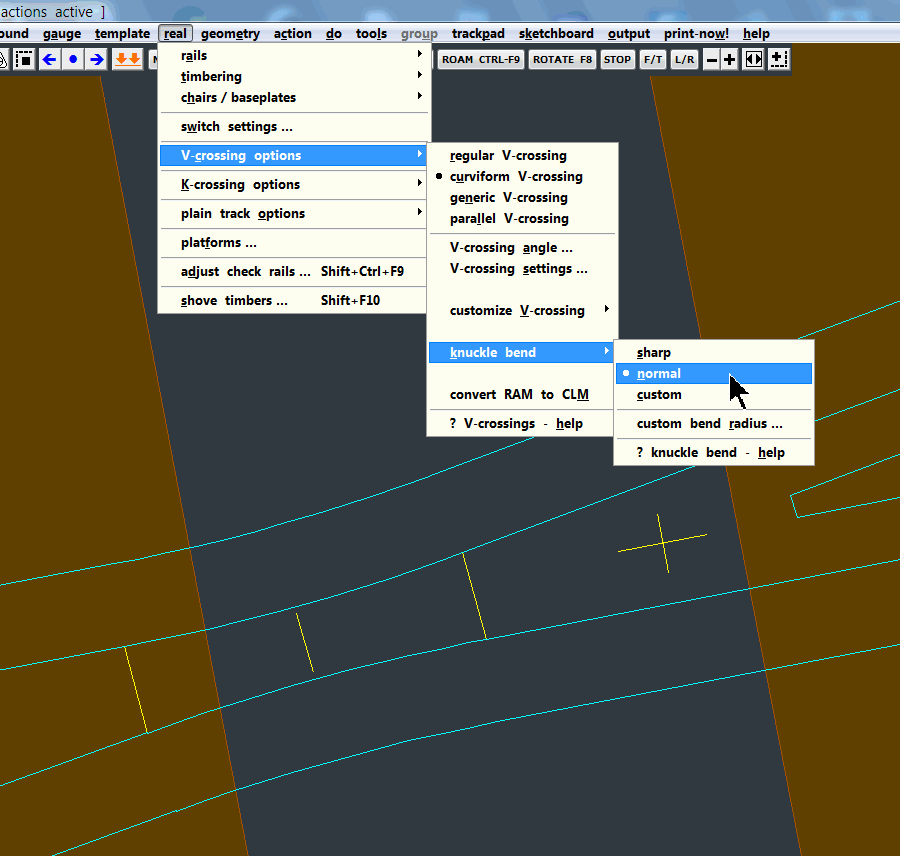
  • Knuckle Bend Radius -- see table below (Templot trackpad > real > V-crossing options... > knuckle bend > custom bend radius...)
All the rails (with two exceptions) are inclined at 1 in 20 to the vertical (approx 2.98°). Curved inclined rails therefore require the head of the rail to be a different radius to the foot of the rail i.e. a conical curve. This can be achieved by using non-parallel rollers as one would when rolling a conical boiler. The two exceptions are:
  1. Check rails. These are vertical so the flare curves are cylindrical.
  2. The point and splice rail assembly between the blunt nose and end of the splice are vertical. From there to the first "normal" chairs (usually S1 or L1) the point and splice rails twist from vertical to 1 in 20. Any intermediate "special" chairs (e.g. B, C, D etc) have a varying inclination to accommodate this gradual twist.
Code:
Xing Angle    Knuckle Bend Radius
1 in 1½       1ft 0in
1 in 2        1ft 6in
1 in 2½       2ft 0in
1 in 3        2ft 11in
1 in 3½       4ft 1in
1 in 4        5ft 4in
1 in 4½       6ft 0in
1 in 5        6ft 8in
1 in 5½       7ft 4in
1 in 6        8ft 0in
1 in 6½       8ft 8in
1 in 7        9ft 4in
1 in 7½       10ft 0in
1 in 8        10ft 8in
1 in 9        12ft 0in
1 in 10       13ft 4in
1 in 11       14ft 8in
1 in 12       16ft 0in
1 in 14       18ft 8in
1 in 16       21ft 4in

Data taken from LNER Permanent Way Standards 1926 and LMS Permanent Way 1928. I have seen an Eastleigh copy of these REA standards but I haven't yet been able to source a copy. Note that there are differences between the LNER and LMS versions, in particular rail lengths and timber spacings.
 
_______________
message ref: 3472
Last edited:
Whilst browsing this topic recently I followed a link to one of Martin's pages (Real Track) in the Templot Companion which I wish I'd found a few months ago.
However, when I got to the last section, Wing and check rail dimensions, which deals with the Templot representation (albeit not quite up-to-date:() but I don't think it quite covers the whole story of the prototype. So here's my two pennyworth which I do realise may not have much application to modelling but helps to complete the prototype info.
@S-Club-7

Hi Dave,

That page has been on the web site in one form or another for about 20 years. Which is why the check rail diagram is not up-to-date in showing the knuckle bend radius which Templot has been drawing on the templates for many years now. I must remember to make a new diagram soon.

The default knuckle bend radius in Templot follows GWR practice in that the radius in feet matches the unit crossing angle. So a 1:7 crossing has a knuckle bend of 7ft radius, and so on. Full details of Templot's settings for knuckle bend radius and how to customize it are at:

https://85a.uk/templot/companion/knuckle_radius.php


knuckle_radius1.png


Many thanks for your list of REA knuckle radii which will be very useful for anyone wishing to customize the setting. Those settings tend to be more generous than the GWR settings -- anyone having trouble getting smooth running through crossings could usefully increase the radius from the default.

Regrettably, I still haven't got round to applying a similar bend radius to the K-crossing outer wing rails (stock rails) and K-crossing check rails. Seeing how much still remains to be done in Templot, even after all these years, can be a bit depressing at times. Perhaps those working on the open-source T3 version might like to have a go at it?

As you say, for inclined rail the knuckle bend needs to be a conical bend. The near impossibility of making such a bend in the smaller scales, and similarly of putting the twists in the vee rails while maintaining the running edge straight, is the reason I think using inclined rails in the smaller scales is just plain daft. It causes endless problems including with gauging, and is impossible to see anyway. The one place where it might be noticed would be at the ends of check rails, but they should be vertical of course.

Which means that for the Plug Track project all rails will be vertical throughout, and I'm not open to any argument about that, it's decided. Consequently the Plug Track chairs will not be compatible with inclined chairs from other sources.

Templot can actually draw the 2-D templates with inclined rails, if you change the rail section settings and select the head and foot option (normally intended for flat-bottom rails) and set the foot width to match the head width. The template then looks like this at the knuckle, showing the foot visible beyond the head in plan view, where the rail is not vertical:

inclined_knuckle.png

The usefulness of this to anyone actually building track on the template is near zero, and is less than zero if sensibly using vertical rail. I must check whether the inclination is switched off for the check rails, I can't remember about that now (or much else).

For the check rail flares, I wrote a lot about it recently, so I won't repeat it all here, see:

https://85a.uk/templot/club/index.p...3d-printed-cnc-milled-laser-cut.229/post-2931


index.php


Much the same applies to the wing rail flares, although there are slight prototype differences (related to wing rails being inclined).

cheers,

Martin.
 
_______________
message ref: 3476
Back
Top