Templot Club forums powered for Martin Wynne by XenForo :

TEMPLOT 3D PLUG TRACK - To get up to speed with this experimental project click here.   To watch an introductory video click here.   See the User Guide at Bexhill West.

  • The Plug Track functions are experimental and still being developed. Some of the earlier pages of this topic are now out-of-date.

    For an updated overview of this project see this topic.   For some practical modelling aspects of using Plug Track see Building 3D Track.

    The assumption is that you have your own machines on which to experiment, or helpful friends with machines. Please do not send Templot files to commercial laser cutting or 3D printing firms while this project is still experimental, because the results are unpredictable and possibly wasteful.

    Some pages of this and other topics include contributions from members who are creating and posting their own CAD designs for 3D printing and laser-cutting. Do not confuse them with Templot's own exported CAD files. All files derived from Templot are © Martin Wynne.
  • The Plug Track functions are experimental and still being developed.

    For an updated overview of this project see this topic.   For some practical modelling aspects of using Plug Track see Building 3D Track.

    The assumption is that you have your own machines on which to experiment, or helpful friends with machines. Please do not send Templot files to commercial laser cutting or 3D printing firms while this project is still experimental, because the results are unpredictable and possibly wasteful.

    Some pages of this and other topics include contributions from members who are creating and posting their own CAD designs for 3D printing and laser-cutting. Do not confuse them with Templot's own exported CAD files. All files derived from Templot are © Martin Wynne.

Trying to understand a bridge description

Quick reply >
So a bridge that I'm going to model was described in an inspection survey dated 1905:

"with one span of 70'6 and 3 spans of 60'6 formed by steel plate girders with cross-girders, rail-bearers and floor plates on brick in cement piers and abutments; total length 109 yds."
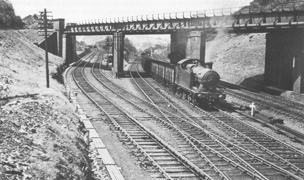
Penrhos1935.jpg

By rail-bearers I presume it means sleepers? Or does it mean longitudinal timbers? With or without ballast?
 
_______________
message ref: 3627
@Penrhos1920

Hi,

Welcome to Templot Club. :)

"rail-bearers" means longitudinal timbers, usually called waybeams. The bridge construction will be something like this:

index.php


"brick in cement piers and abutments" means ordinary brickwork was used for them. "Brick-in-cement" should normally be hyphenated, i.e. in contradistinction to older traditional work using lime mortar. Portland cement was new in the 19th century:

https://en.wikipedia.org/wiki/Lime_mortar

cheers,

Martin.
 
_______________
message ref: 3628
Hello Martin

I'm guessing that photo of the bridge is yours- you can always tell one of yours as you wait until the trains have gone. If so, could I possibly ask permission to download it for personal use, please?

For years I've wanted to build something but never could- time and space, also the M word. But that looks ripe for a very small diorama.

Interesting to see the welded BH rail to the left. I've never seen that before, although I've read you and others talking about it.

BTW if the OP doesn't mind me adding this to his question: is there any rule about whether to use longitudinal beams or transverse sleepers with ballast? From what I've seen length, height of the deck, speed of trains- nothing seems to have a definitive factor as to which method is chosen.

Thanks
Derek
 
_______________
message ref: 3632
A lot will depend on the era that you intend to model, these days heavily used lines are being converted to ballast and sleepers as it distributes the loads better, the downside is that it makes the bridge inspection more difficult, as the ballast should ideally be removed first. There have been a few close shaves with regards bridges being on the verge of failure, due to poor inspections.
 
_______________
message ref: 3633
Hello Martin

I'm guessing that photo of the bridge is yours- you can always tell one of yours as you wait until the trains have gone. If so, could I possibly ask permission to download it for personal use, please?
@Derek

Hello Derek,

Sure, go ahead. Lichfield City 1990.

Here are a couple more. These are higher resolution versions:

lichfield_city_sb_bridge_may1990_1800x1040.jpg


lichfield_city_sb_bridge2_may1990_1800x1040.jpg


lichfield_gf_may1990_1800x1080.jpg


cheers,

Martin.
 
_______________
message ref: 3634
Many thanks Martin

Just as a point of interest, the left two tracks over the bridge with the background is uncannily close to an artist impression of a station that was planned near me but never built. The usual thing- miles of embankment, then ran out of money...

NB the modern view of the station is very different with just the two inner tracks remaining and now disfigured by the overhead wires.

Thanks again
Derek
 
_______________
message ref: 3649
Back
Top