Search
bordercollie
Member
- Location
- Australia
Hi
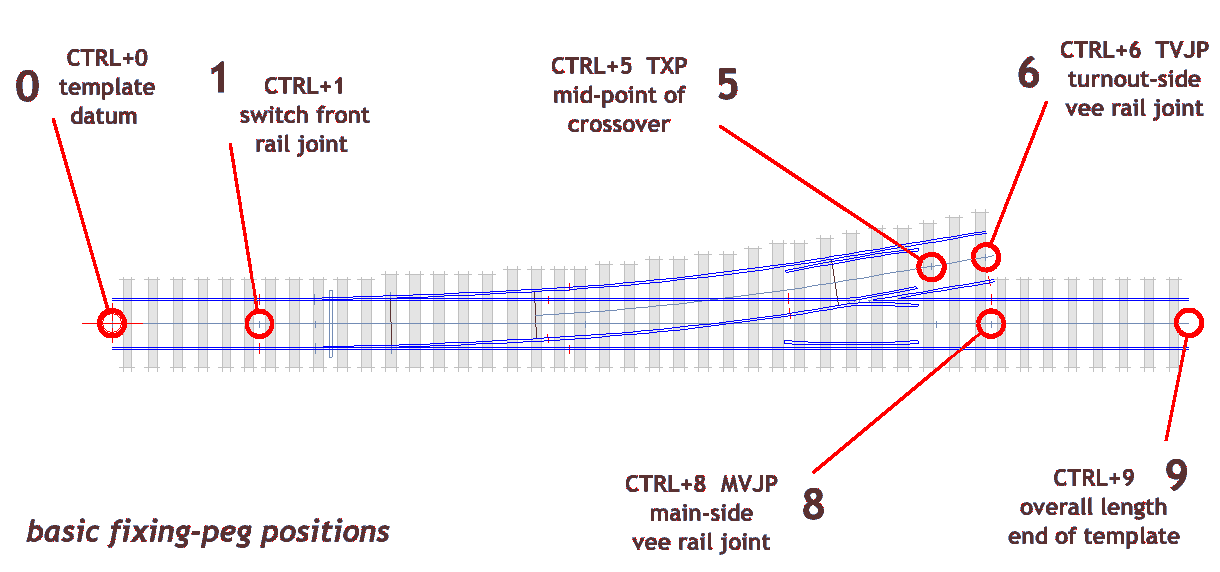
I have been struggling for some time as to where to place the rail joints on turnouts and crossovers. Please see attached file. As an example I have used a GWR old style 12' 1:8 turnout and gauge of 18.83mm. I have placed the the peg on MXP, MVJP, TVP and TVJP using 4 separate templates. I understand these to be main road crossing point, main road rail joint, turnout crossing point and turnout rail joint respectively. Could you confirm that this correct? In the book from David Smith I see that the V leg distance from crossing intersection to rail joint should be 12'. I realise that the V length varied in crossovers but in my 1:8 crossover (not shown on the attached fie) there was a similar problem. When using the spacing ring the 12' circle did not match any of the pegs or the five marks (three on turnout and two on main road) on the track centre line. Its clear that there is a gap in my understanding. Should I just make the rail joints at the 12' point on turnouts or the appropriate lengths as per Table 9 of Smith for crossovers?
Best wishes
Graham
Attachments
message ref: 2081