Search
Steve_Cornford
Member
- Location
- Brighton, East Sussex
Yes it was the colour that sparked the question, looks a bit like birch ply, but i suppose a bit irrelevant once painted & weathered.
message ref: 11148
TEMPLOT 3D PLUG TRACK - To get up to speed with this experimental project click here. To watch an introductory video click here. See the User Guide at Bexhill West.
 Thanks. Thanks.
@Steve_CornfordYes it was the colour that sparked the question, looks a bit like birch ply, but i suppose a bit irrelevant once painted & weathered.
")
@Hayfield
Hi John,
You asked for some pictures of 7mm/ft scale plug track. Here are a few bits. You know how difficult the resin is to photograph, and no sun today to help. The rail is C&L code 131. The P4 turnout is a B-7 for size comparison.
1 raft of S1 and L1 with solid jaws.
1 raft of S1 and L1 with slots for loose jaws.
View attachment 9257
View attachment 9259
View attachment 9258
View attachment 9260
cheers,
Martin.
Thanks. Thanks. Thanks. Thanks. Thanks..
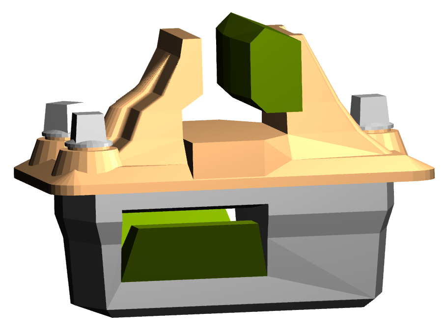
Among other new functions in 244d I've mentioned, is this one:
https://85a.uk/templot/club/index.php?posts/10918
which reduces the 7mm/ft plug depth to just under 3mm, matching the 4mm/ft plugs:

Ignoring the note in blue, I'm wondering if the track is built on a slab of expanded polystyrene, would the long loose jaw pins push down into it without needing any preparation? Then turn the track over after assembly and snip them off flush from below.
So much stuff still to try.
More info: https://85a.uk/templot/club/index.php?posts/10918
cheers,
Martin.
Thanks.@Steve_CornfordHi Martin,
Thinking Cap Tuesday heralds another enhancement request.......
In Templot there is the option to display on the trackpad, and also to print a representation of the switch-drive slot (or tie-bar mark)
As part of the geometry of this notional creature, would it be possible to add a couple of user defineable target marks (relative to say the long centreline and the MS end of the tie bar, as these could then be used to drill a pair of fixing holes for servo drive units etc.
For instance here is an example using the required fixing holes for a Makeitminiature servo unit, which are +/-17.5mm away from centreline, and 54mm apart.
View attachment 9335
I guessed where to add the rectangle as a guide to where to add the two clips, then converted them to targets.
When used for plugtrack bases, I then amended the targets back to clips and revised the rectangle shape to give:-
View attachment 9336
which when exported as 3D for FDM gave me:-
View attachment 9337
The idea being that one lays the turnout, drills through the target(clip) holes, then cut-off the now redundant targets (or bury in ballast)
The important factor is being able to define the location of two holes relative to the middle of one end of the switch-drive slot
If one could also define the size of the square hole in this servo fix point, even better.
Could be used with Exactoscale Tortoise mounting plates, MakeitMiniature mounts, Dingo Servo mounts etc, etc.
Oh and while we are about it, can we also add up to two Servo drive targets to the Tie-bar mark, to aid drilling the holes for the actuating rod(s) .
Steve
Thanks. Thanks. The pins would push through into it easily. Answers on a postcard for something more practical. I have tried expanded polystyrene, but the surface is too resilient for the pins to penetrate. Thanks.@Steve_CornfordMy improved version of using clips to indicate servo fixing points drilling position. Positions calculated relative to S1 timber rather than switch-drive slot. Reduced depth of clips as they are only used to indicate drilling position (in this case of a MakeitMiniature servo mount).
View attachment 9345
Is there a way in shove timbers to know the absolute twist of timber S1, so that i can twist a rectangle to match the alignment of timber S1. I cheated in above example as it was a straight turnout.
Sorry Martin, just experimenting with what you have given us so far.
Steve
Hello Martin.
Just a reminder for those new to plug track who haven't read through the previous 973 pages.
In plug track you don't slide the rail into a chaired timbering base*, as if building a plastic turnout kit.
For the intended way of working instead, see:
https://85a.uk/templot/club/index.php?posts/11201
*unless you have a specific reason to do so -- it's your railway.
Martin.
Thanks.Firstly on the crossover, I have lengthened sleepers to cover both tracks - but I can't see an option to add the extra 2 chairs?
Secondly, on the single slip, it has added chairs for most of the diamond, but not converted a few of these to slide chairs and the central section of the crossing has been left unimplemented.
Thanks.@Steve_Cornford@Steve_Cornford
Hi Steve,
As I mentioned, currently it is not straightforward.
I think possibly your best option at present is to add a bonus timber. Use it to position the clips, and then omit it from the export:
View attachment 9349
After adding it, set zero on S1, and then on B1 set the centre spacing back (negative) to the hole positions. Adjust the length and throw to get the ends of the bonus timber at the hole centres. Then manually position the clips over the ends of the bonus timber.
The bonus timber will move and curve with the template. But don't forget to omit it before exporting.
I will see about getting a proper function done to put such fixing holes in defined positions.
To find the angle at the S1 timber, slide the peg along the main road centre-line (CTRL+F8) until it is over the centre of S1, and then look in the info panel:
View attachment 9350
(Add or subtract any twist applied to S1 in the shove timbers.)
Martin.
Hi Martin, may I suggest a phenolic foam sheet or block, better known as floral foam block.The latter option needs some thinking about. My best guess so far is to build the track on a slice of stale bread.
Thanks.@Steve_CornfordHi Martin,
As it is raining here in Brighton, I have been enjoying a Templot learning experience!
Rainy day question
As far as rectangle shapes are concerned, if i call the point at which the diagonals intersect the centre of gravity , would i be right in assuming that when you twist a rectangle shape Templot applies the rotation about the c.o.g.
Steve
Thanks.