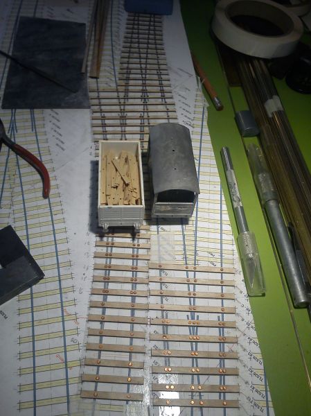
Templot Club Archive 2007-2020
|
|||
| author | remove search highlighting | ||
|---|---|---|---|
|
posted: 11 Jan 2010 20:30 from: Richard_Jones
click the date to link to this post click member name to view archived images |
Hi Guys (and Gals?) I am a new user of Templot, which I bought to help me plan a model of Singleton - ex LBSCR, West Sussex - 4mm, EM gauge. Currently I am working on two options, a) a straight plot of the 1:2500 OS map, which as you can imagine gives a rather long layout (20' + to get the interesting bit in, and b) a curved version (inspired by the late Chris Matthewman's "Striving" ) that would in theory fit in my 18' x 12' living room (occasionally) In a nut shell, does any one have any comments on the "model of a railway" versus the "model railway" approach Also some of the turnouts look very long - does anyone know what sort of geometry the LBSC would have used to lay out the track in the 1880s? (ie preferred crossing angles) any hints on double slips? best wishes Richard Jones Wirral ps illustration of approach b) attached for any comments or suggestions - I can't add the illustration of approach a) as this is the OS map and would breach copyright! 1763_150741_460000000.jpg 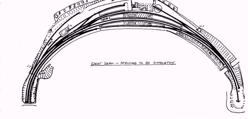 |
||
| Last edited on 15 Jan 2010 12:43 by Richard_Jones |
|||
|
posted: 24 Feb 2010 13:51 from: Martin Wynne
click the date to link to this post click member name to view archived images |
Richard_Jones wrote: Hi Guys (and Gals?)Bump. No replies for Richard? |
||
|
posted: 24 Feb 2010 15:54 from: Stephen Freeman
click the date to link to this post click member name to view archived images |
Curved turnouts = long turnouts. Curved Double Slips!!!= evener longer. Don't get me started on outside slips! |
||
|
posted: 24 Feb 2010 16:46 from: John Lewis
click the date to link to this post click member name to view archived images |
Richard Singleton - on - the - Bend You do not say the period you are to model - will you have short 4-wheel coaches or ordinary 8-wheel ones? It is your railway and if the LBSCR made the mistake of not curving the line so a model will fit in your living room, then you put them right! The things to watch are the minimum radii, especially on the crossovers, and the spacing between the tracks on the curve. Do you know why the station had 4 platform faces? It does look an interesting plan. |
||
|
posted: 24 Feb 2010 17:37 from: Jim Guthrie
click the date to link to this post click member name to view archived images |
Borg-Rail wrote: Curved turnouts = long turnouts.Agreed . On the track plan I uploaded the other day, a simple crossover between the up and down main on a 53" radius curve requires a 1:16 crossing on the turnout on the outer line with its crossover road being just over 43" radius. I did try to get a larger inner radius by trying for even higher crossing numbers but Templot seemed to object. If you do go for the curved version of the layout you will have to be prepared for these large number crossings and your diamonds and slips will have to be the switched versions to get reliable running. Further on reliability, you will have to use good track and wheel standards so that the wheels don't drop into the very long gaps in front of these long crossing noses. Jim. |
||
|
posted: 24 Feb 2010 19:00 from: Richard_Jones
click the date to link to this post click member name to view archived images |
John Lewis wrote: RichardJohn, Thank you for your comments I am intending to model in the 1930's SR period for the rolling stock so that generally it will be bogie stock though lots of 4 wheel horse boxes (see later). I will alter history slightly as the turntable was removed in the early '20's and assume that the line didn't loose its traffic that led to removal of passenger services in 1935. The station was built with an eye to " lucrative race traffic" to Goodwood hence the very generous platform and bay facilities - in reality the station was very busy for 2-3 days and virtually deserted the rest of the year. Even then the Pullman race specials used Drayton & Chichester, and only the 3rd class excursions went to Singleton - my ideas for rolling stock will suggest that it worked out how the Brighton envisaged! I'm still undecided on the straight/curved option and am trying both in Templot regards Richard |
||
|
posted: 24 Feb 2010 19:11 from: Richard_Jones
click the date to link to this post click member name to view archived images |
Dear Borg-rail & Jim, thanks for your observations - I am still undecided and am trying both in Templot, however if I can get something that can be set up at home, my inclination is to try and build as close to the prototype as possible, but even then those crossovers were coming out at 1:12. I know this will display my ignorance, but how will I know if the prototype used an inside or an outside double slip? All comments gratefully received Richard |
||
|
posted: 24 Feb 2010 21:28 from: Jim Guthrie
click the date to link to this post click member name to view archived images |
Richard,I know this will display my ignorance, but how will I know if the prototype used an inside or an outside double slip?You would have to try and get photographic evidence if you could. Large scale OS maps do show trackwork details but I'm never too sure how accurate these might be in complex formations. If you go for your curved version of the layout then it will be up to you. The choice between inside and outside slip will be set by the basic criterion of whether you can get an inside slip road at an acceptable radius. If not, then its an outside slip. Basically slips tend to be between 1:6 and 1:8. If you go below 1:6 then you are getting in to outside slip territory. I remember a friend who was involved in P & C design work in BR many years ago saying that trackwork should flow, and the use of an outside slip in a complex formation can help that formation to flow much better than an inside slip road. Jim. |
||
|
posted: 24 Feb 2010 21:37 from: Nigel Brown click the date to link to this post click member name to view archived images |
Hi Richard Straight versus curved? First question, in practice how easy will it be to re-arrange your lounge to accomodate things, set things up, and restore things afterwards, and how long can you keep the layout set up? In other words, is the hassle going to be worth whatever you manage to get out of the layout when it is set up? Second question, is your primary interest in building the thing or in running it once its built? And are you interested in exhibiting it? If you are interested in exhibiting it, and home running isn't the major aim, perhaps thinking in terms of just assembling bits of it at home for working on and testing purposes might be the way to go. Third question, do you have anywhere else you could assemble it, e.g. loft or garage? Think it boils down to what you really want, and can work out somewhere to fit it in. The curved version won't be a model of the station, rather "based on"; if you go for this I wouldn't hesitate to alter the track layout as well to get rid of any awkward things, such as those others have suggested. The straight version isn't an awful lot of point if you're never going to have anywhere where you can set it up (home or exhibition or other); on the other hand if there are options to set it up occasionally might be more satisfying. Only you know! cheers Nigel |
||
|
posted: 24 Feb 2010 21:47 from: Martin Wynne
click the date to link to this post click member name to view archived images |
Jim Guthrie wrote:On the track plan I uploaded the other day, a simple crossover between the up and down main on a 53" radius curve requires a 1:16 crossing on the turnout on the outer line with its crossover road being just over 43" radius. I did try to get a larger inner radius by trying for even higher crossing numbers but Templot seemed to object.Hi Jim, Templot will go to much flatter angles than 1:16. But it will object if the V-crossing angle is flatter than the switch heel angle. To change to a flatter crossing angle, first change to a longer switch. The limits are these: A-switch up to 1:14 B-switch up to 1:18 C-switch up to 1:22 D-switch up to 1:27 E-switch up to 1:36 F-switch up to 1:46 If you use the F5 mouse action to change the turnout size (and you are not using a custom switch), Templot will change the switch size automatically. To ease the radius in curved turnouts using these very flat crossing angles, you should also change to generic or curviform pattern V-crossings (generic only, if in a crossover). For regular V-crossings, the turnout radius won't ever exceed the switch radius, regardless of the crossing angle. regards, Martin. |
||
|
posted: 25 Feb 2010 21:52 from: Jamie92208 click the date to link to this post click member name to view archived images |
Go with what you think looks right. A curved layout often looks more visually appealing than a straight one. The long crossing angles do work but swing nose crossings make them much more relaible. The only thing is to turn down the power of your point motor so tnhat it doesn't distort the crossing V when it swings if you are using a Tortoise. I changed the operating wire to a thinner one as the pivoted V moves much more easily than a rail that is being bent. On a personal note I am very interested in your remarks about striving and will make sure that his widow is made aware that people have been inspired by it. Chris'r last layout 'Striven'is now back on the road under new ownership and will be at the Wakefield show this year with some of Chris's old operating team helping to run it. Jamie Guest |
||
|
posted: 28 Feb 2010 22:59 from: Richard_Jones
click the date to link to this post click member name to view archived images |
Jamie92208 wrote: Go with what you think looks right. A curved layout often looks more visually appealing than a straight one. The long crossing angles do work but swing nose crossings make them much more relaible. The only thing is to turn down the power of your point motor so tnhat it doesn't distort the crossing V when it swings if you are using a Tortoise. I changed the operating wire to a thinner one as the pivoted V moves much more easily than a rail that is being bent.Thanks for your comments - as I previously mentioned I am re-appraising what I might be able to set up at home so that I would not be restricted to exhibition running which would have been dictated by a layout based rigorously on the OS map. Since I drafted the curved layout idea we have had an old wood/plastic conservatory replaced with a proper room that opens off the back of the living room and connects to the dinning room, so I have more flexibility over "available" space. I agree with your comment about curved layouts being more interesting - some of the photos of Singleton in the Middleton Press books give more of an impression of a curve than the OS map shows (apparently it was 52 chns radius at the Northern end of the station) I saw "Striving" at Expo EM North several years ago and have a photo of my friend Paul Nelson at the controls - Paul was (I believe) originally a member of Wakefield Club before he moved across the Pennines to Wirral - I usually try to encourage him to start model building again when our paths cross. best wishes Richard |
||
|
posted: 4 Jul 2010 22:44 from: Richard_Jones
click the date to link to this post click member name to view archived images |
Here's another attempt at a curved version given the space now available following building work...... 1763_041742_490000000.jpg 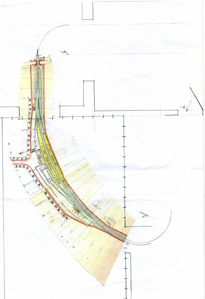 |
||
| Attachment: attach_819_1010_new_curved_version.box 605 | |||
| Last edited on 4 Jul 2010 22:46 by Richard_Jones |
|||
|
posted: 5 Jul 2010 11:32 from: JFS
click the date to link to this post click member name to view archived images |
Richard, I think it looks a lot better - but it rather appears from the image that at the Lavant end you would be looking at it through a rather narrow opening. For me, this was the more interesting end of the station and a good view of it would be important. Also, where do you envisage the normal viewing position? From the outside of the curve, the station was largely hidden by tall trees as I recall, (though they would have perhaps been a lot less tall in LBSC days!)whereas from the inside of the curve you would be looking down from the top of West Dean hill... Best Regards, Howard. |
||
|
posted: 5 Jul 2010 19:35 from: Richard_Jones
click the date to link to this post click member name to view archived images |
Hi Howard, many thanks for your comments - I would envisage the normal viewing point would be opposite the station building, looking up the approach road, however the aim of this scheme was to have something that (could) go to exhibitions, but could also be set up at home (if it never achieves the former!) - hence the floor "footprint". At the Lavant end, the width is dictated by the opening into the new room where the conservatory used to be (4' window removed) and at the "Cocking" end by the 2' 6" door way into the hall - the scenic breaks being an overbridge ( Any other suggestions, hints etc gratefully received. best wishes Richard * correction 27/06/2019 - my mistake - "Bulldog Bridge" is between Singleton and Cocking Tunnels - the overbridge for the scenic break is for a farm track to Hat Hill, and I am told is called "leg of Mutton" |
||
| Last edited on 27 Jun 2019 14:27 by Richard_Jones |
|||
|
posted: 5 Jul 2010 22:41 from: JFS
click the date to link to this post click member name to view archived images |
I think it would make a good exhibition layout (providing that you only operate the Race Days TT!) I know that your original query related to LBSC point geometry - are you a member of SEMG? There is a diagram published in the Photos section at http://groups.yahoo.com/group/SEmG/photos/album/1281883701/pic/1086912143/view?picmode=&mode=tn&order=ordinal&start=1&count=20&dir=asc but you need to be a member to be able to view it. It might be of limited use as it relates to Standard Leads but may provide a starting point (no pun!) Best Regards, Howard. |
||
|
posted: 6 Jul 2010 06:44 from: Richard_Jones
click the date to link to this post click member name to view archived images |
Hi Howard, No I'm not a member of SEMG, but I often look at the photo pages and pull off the latest edition of "Coupe News" which is a mine of infomation on Pullmans (for those race specials, though in reality the Pullman race specials ran to Drayton rather than Singleton...) I am in the Brighton Circle E group, and Mike Waldron (EB Models) has recently started a thread on that forum regarding LBSC track geometry and has mentioned Templot templates, so I am hoping he may share these in this forum. best wishes Richard |
||
|
posted: 12 Jul 2010 16:55 from: Mike Waldron
click the date to link to this post click member name to view archived images |
Richard: there's probably value in contacting John Ritter (ex-pat in Australia) on the Brighton Circle egroup. Mike Waldron |
||
|
posted: 12 Jul 2010 16:59 from: Mike Waldron
click the date to link to this post click member name to view archived images |
Richard_Jones wrote:Hi Howard, Hi Richard: there is some information on the Brighton Circle egroup section of the Website - but I can recommend John Ritter's expertise. he has done some research and seems fairly clued up on Brighton track. |
||
|
posted: 12 Jul 2010 17:00 from: Mike Waldron
click the date to link to this post click member name to view archived images |
if you want his address contact me on mike@mjwsjw.co.uk off group. Mike |
||
|
posted: 14 Jul 2010 12:47 from: Richard_Jones
click the date to link to this post click member name to view archived images |
Hi Mike, Thanks for the suggestion - I have recently been in touch with John, who kindly provided a drawing for a crane match truck. Coincidentally, its rather a small world, as it turn out that when John was visiting another ex-pat who had retired back to the UK (Don Chapman, sadly no longer with us) I ended up taking both John and Don to EXPO EM North at Slaithwaite, so it was nice to re-establish contact. Don had a model of Bangor (LNWR) in his loft and would run the "Irish Mail" with 14 coaches and on a couple of occassions managed to "strip" the gearbox on the loco! I understand that the station section of the layout has gone to the Brookside Garden Centre. best wishes Richard |
||
| Last edited on 10 Jan 2012 13:05 by Richard_Jones |
|||
|
posted: 3 May 2011 19:07 from: Richard_Jones
click the date to link to this post click member name to view archived images |
Hi Guys & Gals, I had another "outline" go at Singleton, this time on a continuous curve, rather than the final bit straight (which is prototypical) - any comments on which looks better? many thanks Richard1763_031407_070000000.jpg 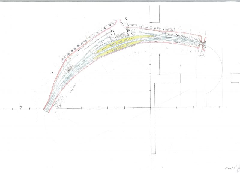 |
||
|
posted: 3 May 2011 21:47 from: JFS
click the date to link to this post click member name to view archived images |
Hi Richard, Looks good - have you put this in the image gallery? I can't seem to be able to load a larger version to see the detail. Best wishes, Howard. |
||
|
posted: 4 May 2011 13:27 from: Phil O
click the date to link to this post click member name to view archived images |
Hi Guys & Gals, Hi Richard This looks to be a closer rendition of the prototype, going by your earlier post with the map. I prefer layouts on curves rather straights with a semi circle at each end, they always appear to be longer to my eye. Cheers Phil |
||
|
posted: 5 May 2011 22:14 from: Richard_Jones
click the date to link to this post click member name to view archived images |
Hi Howard, I think I have put it in the image gallery.... If it's not there please let me know, and I'll try to oblige (I may need some instruction!) sorry I'm a neo-luddite best wishes Richard |
||
|
posted: 16 May 2011 23:04 from: Richard_Jones
click the date to link to this post click member name to view archived images |
Borg-Rail wrote: Curved turnouts = long turnouts.Hi there, If you see my latest effort, I'm working on a ruling 15' radius with 1:8 crossings - do you think this practical in EM? many thanks Richard |
||
|
posted: 17 May 2011 20:21 from: JFS
click the date to link to this post click member name to view archived images |
Hi Richard, 15' almost counts as straight in 4mm terms! If in doubt, you could build an example off the template and try it out before you commit to building the whole plan, but I would have thought that you would get away with it even in EM though the middle of the double slip will be a bit crowded due to the overscale flangeways. I picked up your image in the gallery by the way, and I think you have done a nicely subtle job of compressing and curving the layout. Just in terms of how to upload and link images, in this topic, topic 1172 you will find Martin's response to my query on the same issue - hope it helps. Best Wishes, Howard. |
||
|
posted: 15 Jun 2011 21:57 from: Richard_Jones
click the date to link to this post click member name to view archived images |
Ladies & Gentlemen, Please find attached the BOX file for my interpretation of Singleton - I haven't yet properly finished the double slip (just a crossing at the moment), the tandem turnout or any of the catch points, but any views on how it looks/suggestions for alteration would be gratefully recieved many thanks Richard |
||
| Attachment: attach_1286_1010_curved_version_2_colour_005.box 396 | |||
| Last edited on 29 Dec 2011 11:47 by Richard_Jones |
|||
|
posted: 15 Jun 2011 21:59 from: Richard_Jones
click the date to link to this post click member name to view archived images |
SHAPE file to go with BOX file for Singleton |
||
| Attachment: attach_1105_1010_curved_version2_colour.bgs 420 | |||
|
posted: 15 Jun 2011 22:11 from: Martin Wynne
click the date to link to this post click member name to view archived images |
Hi Richard, Thanks for uploading your files. For the background picture shape, you need to send a third message, and add the BMP image file for the picture shape. It may take a few minutes to upload after you click Send. There is a size limit of 5.7MB. regards, Martin. |
||
|
posted: 16 Jun 2011 18:24 from: Richard_Jones
click the date to link to this post click member name to view archived images |
.bmp file ..... finally after compression! |
||
| Attachment: attach_1106_1010_Singleton_curved_version2_copy.bmp 647 | |||
|
posted: 16 Jun 2011 20:36 from: Martin Wynne
click the date to link to this post click member name to view archived images |
Richard_Jones wrote: .bmp file ..... finally after compression!Hi Richard, Thanks for uploading it. Unfortunately, Templot can't handle RLE-compressed BMP files (run-length encoding). I've attached it again below in PNG format. (Right-click on the link and click Save Image As..) Templot 091c can't load PNG directly (TDV can), so anyone wanting to try it will need to open it in a graphics editor such as Irfanview or Windows Paint, and then save it again in BMP format for Templot. Then to get it into the picture shape on your track plan, select the picture shape in the list and then click the modify shape: > picture content: > reload... button. regards, Martin. |
||
| Attachment: attach_1107_1010_singleton.png 808 | |||
|
posted: 16 Jun 2011 23:33 from: Richard_Jones
click the date to link to this post click member name to view archived images |
Hi Martin, Thanks for that, I afraid I'm more than a bit of a neo-luddite - the original file (in colour) was 50 Mb, so I was desperately trying to get the file size down...... cheers Richard |
||
|
posted: 23 Oct 2011 11:54 from: Richard_Jones
click the date to link to this post click member name to view archived images |
Ladies & Gentlemen, To echo the message under "printing query", here's a photo showing some full size (4mm scale) laid out (in situ) on the floor to get an idea of how it will all work (on high days and holidays only) - really its an exhibition layout, if it's ever good enough! 1763_221653_080000000.jpg 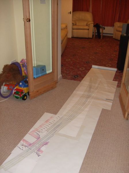 best wishes Richard |
||
|
posted: 7 Dec 2011 15:58 from: Paulr1949
click the date to link to this post click member name to view archived images |
Richard It's been out for a while, but I've only just got round to reading my copy, but have you seen the latest edition of Southern Way? It has a 20-page article on Singleton Looking good! regards Paul |
||
|
posted: 7 Dec 2011 19:46 from: Richard_Jones
click the date to link to this post click member name to view archived images |
Hi Paul, Yes, its a good article - as I've been researching Singleton for some while I had seen much of the material before, the only really useful thing (to me) was the view of the South Signal Box. I've been in touch with the editor of Southern Way, so there may well be a follow up article - perhaps someone will come up with a photo of the turntable. I hoping that I may make some progress over Christmas as I've booked leave through to the new year - perhaps I'll tackle the double slip and three way - if I can build those I know I can manage the rst of the track work. best wishes Richard |
||
|
posted: 7 Dec 2011 20:27 from: JFS
click the date to link to this post click member name to view archived images |
Yes, that was the first decent pic I have seen of the South Box. Regarding the turntable, do you know John Minnis? If the picture exists, John has it! If you have doubts about the double slip or three way, that would be a good reason for practising on something else first. (lesson from hard experience of my first P4 layout!) Good luck! And look forward to some pics of the work in progress! Best Wishes, Howard |
||
|
posted: 8 Dec 2011 20:59 from: Richard_Jones
click the date to link to this post click member name to view archived images |
Hi Howard, I've built plenty of turnouts in the past, just not done any double slips and only one three way - its a (little) bit easier for me in EM, though I've built in P4 in the (very distant) past, but went down the EM route when the great schism occurred, and a certain gentlemen would not supply wheels if you were a member of the rival society! I'm a member of the Brighton Circle, so I can probably contact John Minnis via that route. best wishes Richard ps there is a photo of some of my interlaced turnouts in the image gallery (for my KESR layout that still isn't finished!) 1763_041713_410000000.jpg 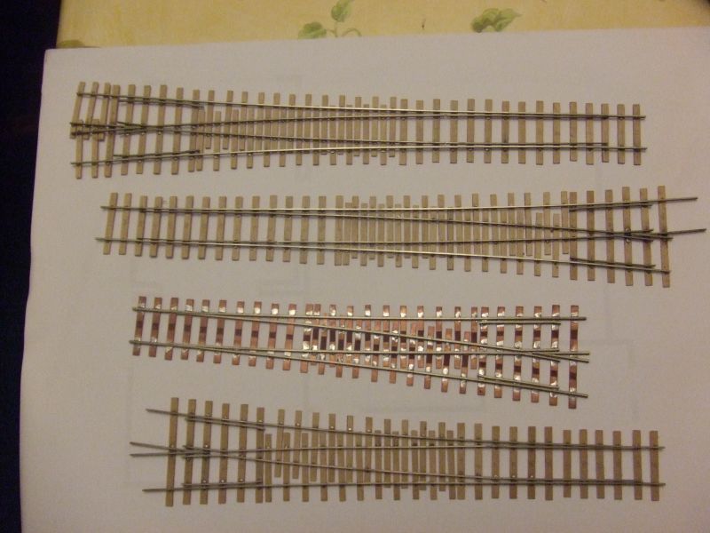 |
||
|
posted: 8 Dec 2011 22:03 from: JFS
click the date to link to this post click member name to view archived images |
Hi Richard, Let me know if you need help getting hold of John, but you should be able to get him via the Circle. Sorry you fell from the True Path - I remember those days and the endless waiting for orders to come and half the things "TF" when they did come. But things are better these days if you fancy coming back to P4!!! Pointwork looks good - good luck with the slip! Best Wishes, Howard. |
||
|
posted: 14 Sep 2012 11:41 from: Richard_Jones
click the date to link to this post click member name to view archived images |
Hi All, I've just uploaded a few photos of some small scale card models I've made to work out baseboard levels and construction, on the basis that cardboard is a lot cheaper than plywood! Now to get on with real thing! best wishes Richard 1763_140631_240000001.jpg 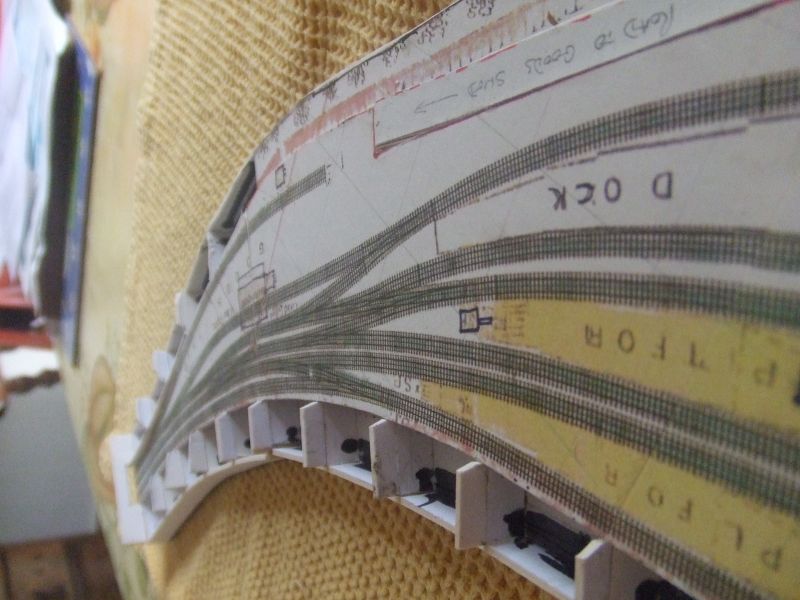 1763_140631_230000000.jpg 1763_140631_230000000.jpg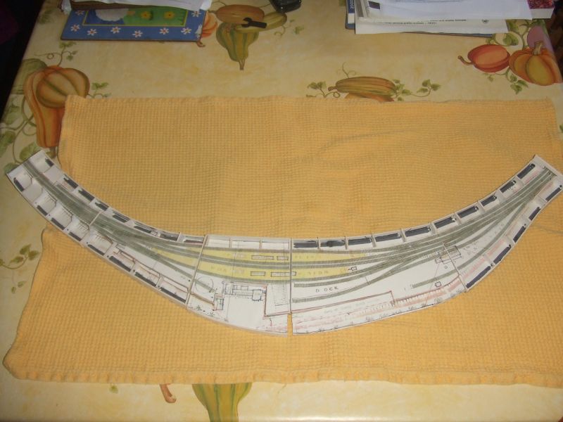 1763_140637_410000000.jpg 1763_140637_410000000.jpg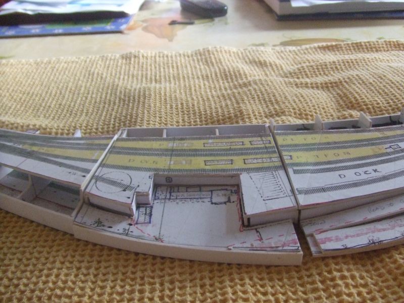 |
||
|
posted: 14 Sep 2012 17:38 from: JFS
click the date to link to this post click member name to view archived images |
Hi Richard, Looking good! Of course your project just got a whole lot easier since Bachmann started doing ready made models of half of your buildings!! Best wishes, Howard. |
||
|
posted: 15 Sep 2012 10:12 from: Phil O
click the date to link to this post click member name to view archived images |
It could almost be a layout in it's own right all you have to do is lay the track and do the scenery. What scale is it? Cheers Phil |
||
|
posted: 15 Sep 2012 21:34 from: Richard_Jones
click the date to link to this post click member name to view archived images |
It's (actually) printed out at 30 mm to 1 (real) foot, and the gauge measures about 2mm off the print outs... Wasn't there someone in Railway Modeller back in the 60s who made a layout driven by wires underneath in a very small scale? Just been inspired by "Glaisden" at Expo EM North to get on with the layout.. cheers Richard (Note: above corrected 21/09/12, when I realised I had stated the scale wrong which I discovered when trying to plan how many sheets of plywood I needed........ |
||
| Last edited on 21 Sep 2012 18:13 by Richard_Jones |
|||
|
posted: 6 Feb 2013 13:50 from: Richard_Jones
click the date to link to this post click member name to view archived images |
Hi All, Progress update - here's a photo of the double slip sitting on the next templates to be worked upon. It already has the vees for the turnouts either side, due to the extended crossing timbers, so I intend to make up the three way/double slip/trailing turnout as a single unit - provided I have a large enough flat surface to work on! best wishes Richard ps have now added the catch points in the appropriate places (not on these templates) pps is it me, or is it easier to print out in the original release of TEMPLOT? 1763_060847_510000000.jpg 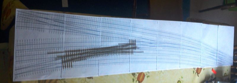 |
||
|
posted: 6 Feb 2013 15:04 from: rodney_hills
click the date to link to this post click member name to view archived images |
Hello, Lots on Singleton here: http://www.amazon.co.uk/The-Southern-Way-Issue-No/dp/1906419639 CONTENTS: http://myweb.tiscali.co.uk/mickssrsource/tpagesrs/tsouthernway.html#e17 Regards, Rodney Hills ps I have the issue somewhere.... |
||
|
posted: 6 Feb 2013 16:56 from: Martin Wynne
click the date to link to this post click member name to view archived images |
Richard_Jones wrote:pps is it me, or is it easier to print out in the original release of TEMPLOT?Hi Richard, In what way? There are two separate printing functions: If you click the OUTPUT > print background templates menu item or press CTRL+F11 it should be exactly the same as before. What are you finding different? The PRINT NOW! > print background templates now! menu item is intended for beginners, and by-passes all the print set up, preview and calibration dialogs. Not recommended if you have a large number of pages to print. regards, Martin. |
||
|
posted: 6 Feb 2013 20:07 from: Richard_Jones
click the date to link to this post click member name to view archived images |
Martin Wynne wroteIn what way?Hi Martin, I think its just "the old dog with a new trick" syndrome.... I'll try the new version again By the way, I don't think "Singleton" would have got this far without TEMPLOT best wishes Richard |
||
|
posted: 6 Feb 2013 20:12 from: Richard_Jones
click the date to link to this post click member name to view archived images |
Thanks Rodney, Yes, I have a copy and have been exchanging emails with Kevin Robertson. The article has a good photo of the South Signal box which I hadn't seen before and some more views of the platform buildings - I still haven't got enough information to accurately model those, but I have just sent off an article to The Brighton Circular which I hope may uncover some more material. Particularly illusive is the turntable (removed in the 1920s) - I haven't seen any photos of that at all! best wishes Richard |
||
|
posted: 5 Mar 2013 14:59 from: Richard_Jones
click the date to link to this post click member name to view archived images |
Progress photo for 5th March 2013. Martin - many thanks - this project would not have got off the ground without TEMPLOT. best wishes Richard 1763_050958_520000000.jpg 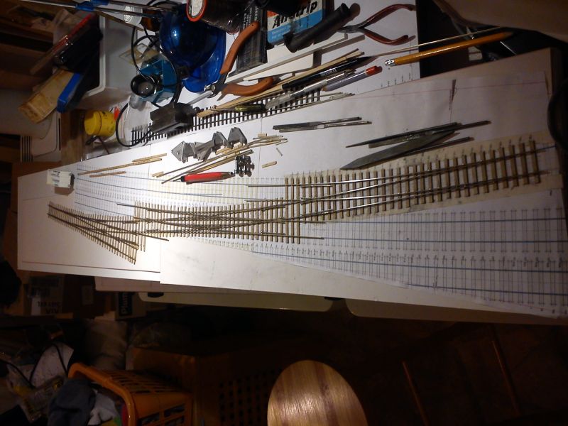 |
||
|
posted: 7 Mar 2013 21:23 from: Richard_Jones
click the date to link to this post click member name to view archived images |
Richard_Jones wrote: Martin Wynne wroteYes, it was "old dog" problem - no idea what I was doing in a "senior moment" but it looks identical to the old version!In what way?Hi Martin, Might be a silly question, but is there a need to do periodic re-calibrations of the printer? cheers Richard |
||
|
posted: 7 Mar 2013 21:36 from: Martin Wynne
click the date to link to this post click member name to view archived images |
Richard_Jones wrote:Might be a silly question, but is there a need to do periodic re-calibrations of the printer?Hi Richard, Your project is looking good. It's worthwhile doing an occasional check on the printer accuracy. If you set the grid to say 50mm or 2" you can simply measure the grid lines on the templates. Or click the output > printer calibration > print proof sheet menu item, and measure it. The printer shouldn't usually need to be re-calibrated, unless you have changed to a different type or batch of paper, or you have printed two dozen copies of War and Peace since the last lot of templates. regards, Martin. |
||
|
posted: 8 Mar 2013 08:59 from: JFS
click the date to link to this post click member name to view archived images |
Richard, It is looking good! You must be pleased that Bachman just made building the Station Building a whole lot quicker Good Luck and best wishes, Howard. |
||
|
posted: 8 Mar 2013 19:51 from: Richard_Jones
click the date to link to this post click member name to view archived images |
JFS wrote: Richard,Thanks for your comments - I've actually got a set of etches that Phil Taylor of the Brighton Circle organised to have "shot down" from 7mm to 4mm from Kirtley Models - these are for the station building - I'm trying to develop as accurate a drawing as I can for the 2 signal boxes and will probaly ask Mike Waldron (EB models) if he can etch (at least) the window frames for me. Still looking for that elusive photo of the turntable.... best wishes Richard |
||
|
posted: 9 Mar 2013 00:31 from: Ian Allen
click the date to link to this post click member name to view archived images |
Keep up the good work Richard, that is coming along very nicely. Ian |
||
|
posted: 9 Mar 2013 12:29 from: Richard_Jones
click the date to link to this post click member name to view archived images |
JFS wrote:You must be pleased that Bachman just made building the Station Building a whole lot quickerHi Howard, I've just checked out the Bachmann buildings and yes, they look very nice and would be quicker, but would still need to be chopped around a bit to do Singleton - certainly the waiting room is the "wrong hand" (and would need to have the Gents removed from the end) - the booking hall may be similar, but from the one photo of each I have seen I can't be certain. and one (not so) small point ....... £129.05 for the booking office + waiting room For the moment, here's the cardboard space model 1763_090724_280000000.jpg 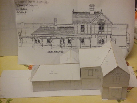 having ordered extra etches, there may be some spares left over - windows, doors etc, if anyone else is tackling a Myers building in 4mm scale - you can see the 7mm etches at: http://www.kirtleymodels.com/index.php?p=1_7_PRODUCTS-0-GAUGE best wishes Richard |
||
| Last edited on 9 Mar 2013 12:31 by Richard_Jones |
|||
|
posted: 24 Aug 2013 22:47 from: Richard_Jones
click the date to link to this post click member name to view archived images |
1763_241737_540000000.jpg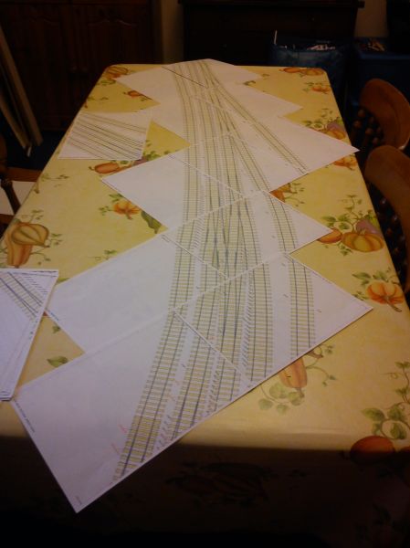 The next tranche of templates printed out - I'm beginning to think I may have bitten off more than I can chew! ....... Cocking end of the station, l to r - up loop headshunt/overrun, up platform becoming running (single) line beyond the crossover, down platform (goods headshunt further side of crossover, line through goods shed and back siding. Next - clear the garage, so I can start building baseboards |
||
|
posted: 25 Aug 2013 09:24 from: JFS
click the date to link to this post click member name to view archived images |
Looking good Richard! Seeing the "mosaic", I wonder if it might be a good investment to get a print shop to print them on a continuous sheet - it avoids the risk of the design creeping out of shape. Just referring to our previous discussion on buildings we were talking about "Myers" buildings but, looking at John Minis' book he talks about "TW Myres" (and the Listing for Horsted Keynes station does the same). That info might help with future Google searches!! Good luck, Howard. |
||
|
posted: 28 Aug 2013 13:05 from: Richard_Jones
click the date to link to this post click member name to view archived images |
Hi Howard, Having gone to print and examined them in detail, I'm not happy with the relative position of the turnouts etc, so have embarked on a radical "tweak" of the "Cocking" end of the station - I'm holding off re-examining the "Lavant" end of the station as I've already built the main pieces of track work for that end! I may well take up your suggestion for a visit to a print shop once I am happy with the final design.... I see Mr Minnis (active member of the Brighton circle) made an appearance on "Unbuilt Britain" on the TV the other evening. best wishes Richard |
||
|
posted: 28 Aug 2013 16:01 from: JFS
click the date to link to this post click member name to view archived images |
He did indeed - and also when Network rail announced the listing of 26 boxes! AND on our local news some months ago when a former filing station on the A1 was listed! Quite a popular chap. Do you have a CAD programme that does basic 3D? (the freebie ProgeCAD will do) You can export your Templot as a 3D DXF and view it from all angles - very helpful when comparing to photos. It saves a lot of this tweaking stuff (which can be a bit stressful...)! Cheers, Howard. |
||
| Last edited on 28 Aug 2013 16:02 by JFS |
|||
|
posted: 28 Aug 2013 19:57 from: Martin Wynne
click the date to link to this post click member name to view archived images |
JFS wrote: Do you have a CAD program that does basic 3D? (the freebie ProgeCAD will do) You can export your Templot as a 3D DXF and view it from all angles - very helpful when comparing to photos. It saves a lot of this tweaking stuff (which can be a bit stressful...)!Hi Howard, Richard, I suggest 3rd PlanIt for that: topic 2297 - message 15275 You can view 3D DXF in the free demo version. You don't have to add the trains: hc_3pi_9.jpg  fremington_3d1.png 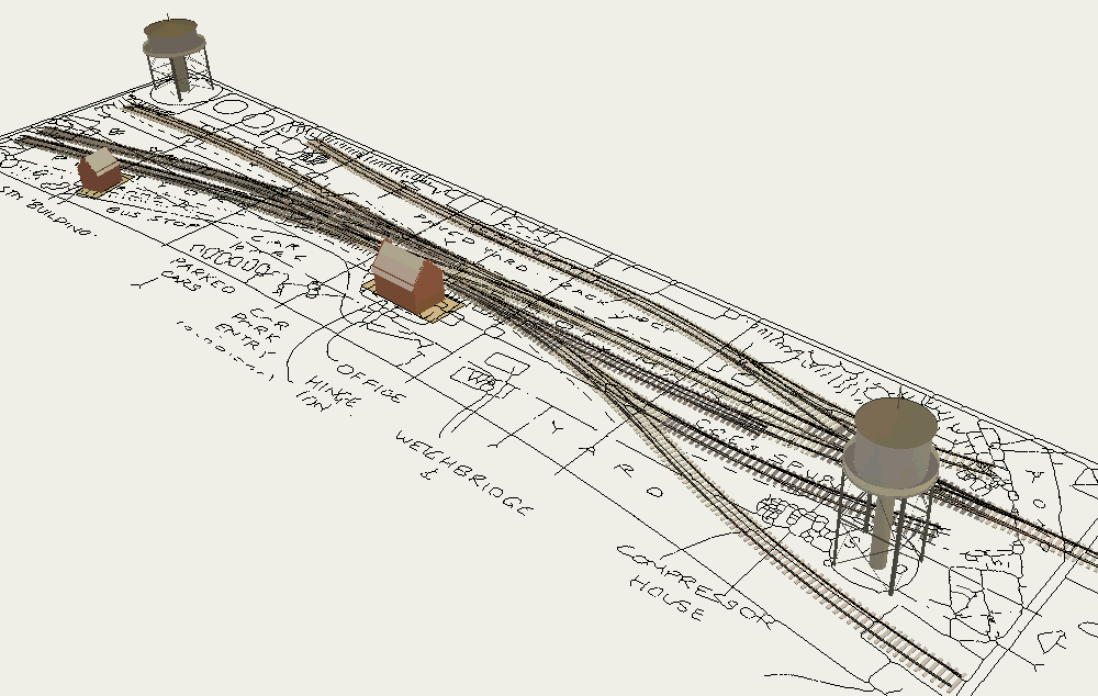 fremington_3d2.png 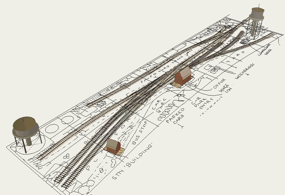 fremington_3d5.png 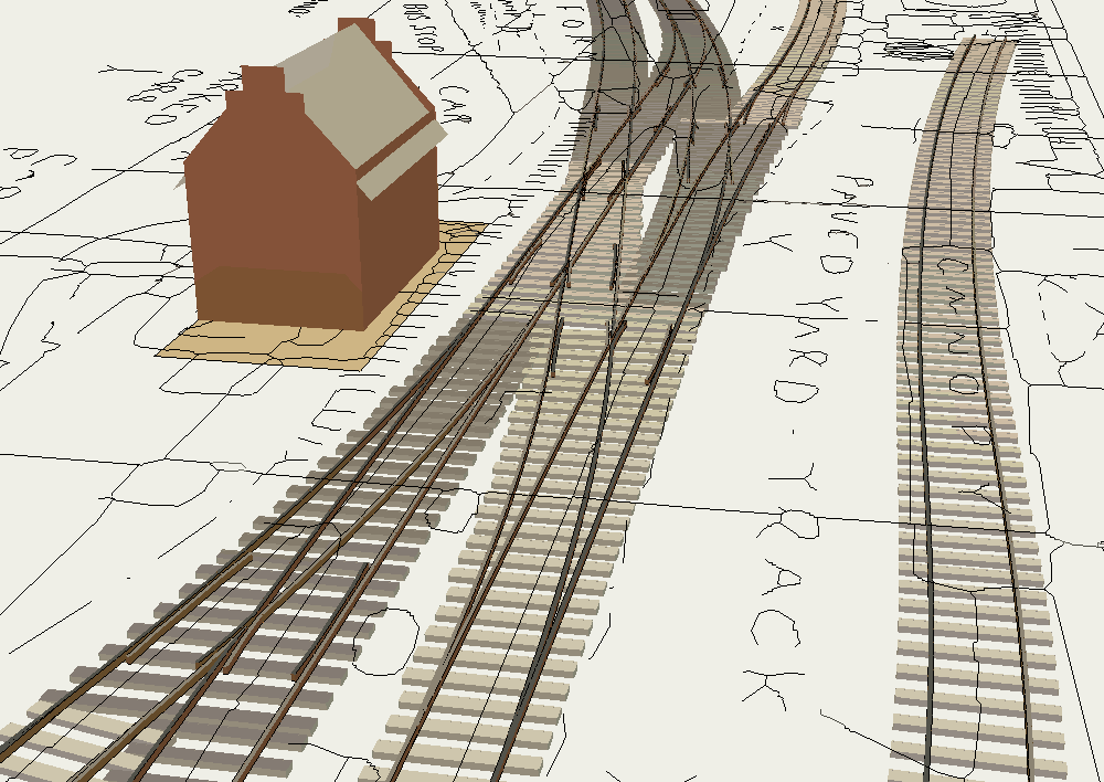 A 100-second video of the above is available for downloading. It's in the usual Templot executable format, but to keep the file size down the frame rate is slower than usual. You can safely open it and ignore any warnings. Press the spacebar to start and stop the playback. (30MB so broadband only, Windows or Linux* only.) Click to download: Fremington 3D video (*on Linux, change the file extension to .zip, and then extract the .avi file. It will play in the VCL player and some others.) regards, Martin. |
||
|
posted: 28 Aug 2013 20:09 from: JFS
click the date to link to this post click member name to view archived images |
Many thanks Martin - I had forgotten about that thread. Best wishes, Howard. |
||
|
posted: 28 Aug 2013 20:13 from: Richard_Jones
click the date to link to this post click member name to view archived images |
Tweaks R Us..... The attached box file is a revision of the "Cocking" end of the station with the tips of the points lined up relative to each other as shown in the coloured plan (West Sussex County Records office) that was reproduced in Southern Way No. 16. Having looked at the "Lavant" end the whole ensemble could do with sliding back a smidgeon, but as I've already built the point work, I believe I can do that effectively by moving the background shape forward. (ie the end of the platforms and the relative positions of the signal box and water tower) This may all sound a bit heretical, but given that the plan has already been distorted to fit a 15' ruling radius on the main running line, I don't think it will distract too much.... Now to try your 3D "thingy", Martin, and see how it looks..... best wishes Richard PS shape file as per previous upload. |
||
| Attachment: attach_1671_1010_Singleton_Final_2_3.box 311 | |||
| Last edited on 30 Oct 2013 21:36 by Richard_Jones |
|||
|
posted: 28 Aug 2013 22:33 from: Martin Wynne
click the date to link to this post click member name to view archived images |
Hi Richard, It's years since I did much on 3rd PlanIt and I'm rusty on all the controls and settings. But here is a locomotive running round your layout. The Jing video may take a few seconds to start while downloading: http://screencast.com/t/eOBwsQZVzs The video is a bit jerky, the view on your own screen is smoother, although the OpenGL 3D rendering is never going to rival the best quality rendering in high-end CAD packages. This is just the barest bones of 3rd PlanIt -- you can work it up to a full layout design with buildings and scenery. I will try to find some old files and post them. Using the native track (Peco etc.) in 3rd PlanIt you can operate points, shunt sidings, couple and uncouple rolling stock, full train simulation etc. On imported Templot track you can run only along the main road. regards, Martin. |
||
|
posted: 28 Aug 2013 22:53 from: Richard_Jones
click the date to link to this post click member name to view archived images |
Hi Martin, That's absolutely brilliant! If I wanted to be a real pedant best wishes Richard |
||
|
posted: 29 Aug 2013 15:33 from: Trevor Walling
click the date to link to this post click member name to view archived images |
Hello, You can view the exe file in Linux if you rename it as a zip file.You then just click on the avi file in the folder and it plays with the suitable video application available. Trevor. Martin Wynne wrote: JFS wrote:Do you have a CAD program that does basic 3D? (the freebie ProgeCAD will do) You can export your Templot as a 3D DXF and view it from all angles - very helpful when comparing to photos. It saves a lot of this tweaking stuff (which can be a bit stressful...)!Hi Howard, Richard, |
||
|
posted: 30 Aug 2013 11:32 from: Richard_Jones
click the date to link to this post click member name to view archived images |
Hi Martin, can you give me a bit of advice on basics! In the box file, Singleton Final 2_1 (attached further up the thread), I've just noticed that I have a bit of discontinuity on the curved crossover formed by templates 67 & 68, where it meets the fill in piece made by template 66 - if I extend this it does appears to be the correct radius. ( I laid the scheme out on a constant radius of the running line, with the down loop parallel) I've tried deleting the crossover and making a new one from the turnout in the main line, but that still doesn't seem to match up on the constant radius of the parallel lines. Any suggestions as to where I am getting it wrong? many thanks Richard |
||
|
posted: 30 Aug 2013 12:27 from: Martin Wynne
click the date to link to this post click member name to view archived images |
Hi Richard, At first sight, template 67 is not on the same radial centre as the running lines. Nor is 68, which appears to be on a much larger radius, and not forming a proper crossover with 67. I have to go now, but I will look at it again later and post a revised version. regards, Martin. |
||
|
posted: 30 Aug 2013 12:43 from: Richard_Jones
click the date to link to this post click member name to view archived images |
Hi Martin, Many thanks for your observations - I'll have a play about with the templates again this afternoon and see if I can sort it by starting again from plain track and re-inserting the turnout before forming the crossover. cheers Richard |
||
| Last edited on 30 Aug 2013 14:15 by Richard_Jones |
|||
|
posted: 30 Aug 2013 13:08 from: Richard_Jones
click the date to link to this post click member name to view archived images |
Richard_Jones wrote: Hi Martin,Hi (again) Martin, That seems to have done it Obviously I can't see the wood for the trees! best wishes Richard ps Previously attached box file replaced by Singleton Final 2_2 pps never ceases to amaze me how that diesel will run through the trap point without derailing - can't stop watching it! |
||
| Last edited on 30 Aug 2013 14:16 by Richard_Jones |
|||
|
posted: 30 Aug 2013 17:09 from: Martin Wynne
click the date to link to this post click member name to view archived images |
Hi Richard, I'm glad you sorted it out. Note that you don't strictly need template 66 (PR373) -- instead you can simply extend some exit track on one of the turnouts (F4 mouse action). Or a short bit of exit track on both of them -- that may or may not help with the rail joints and timber shoving. The same goes for template 51 (PR252). You can extend some exit track on one of the turnouts, or some approach track on the other one (F3 mouse action). Or a bit of both. - can't stop watching it!That explains the email I've just received from screencast.com about my bandwidth limit! regards, Martin. |
||
|
posted: 30 Oct 2013 22:43 from: Richard_Jones
click the date to link to this post click member name to view archived images |
Hi Martin, Can I trouble you for your opinion on part of the layout for Singleton - in particular the crossover to the bay line formed by templates 85/86 with the line back into the bay, and the other pair of turnouts that feed into the second bay line. looking at the photos the vees of 85/86 look to be separated by 2 or 3 sleepers at most - surely this means that there cannot be sufficient clearance, though perhaps it is "protected" by the ground signal by the blades of 85? Bearing in mind that I have distorted the whole lot by curving it to a ruling radius of 15', do you think there is any more I can do to get the Templot layout to better match the two prototype photos? many thanks for any thoughts best wishes Richard (box file Singleton Final 2_3 further up the thread) 1763_301735_000000000.jpg 1763_301735_340000000.jpg 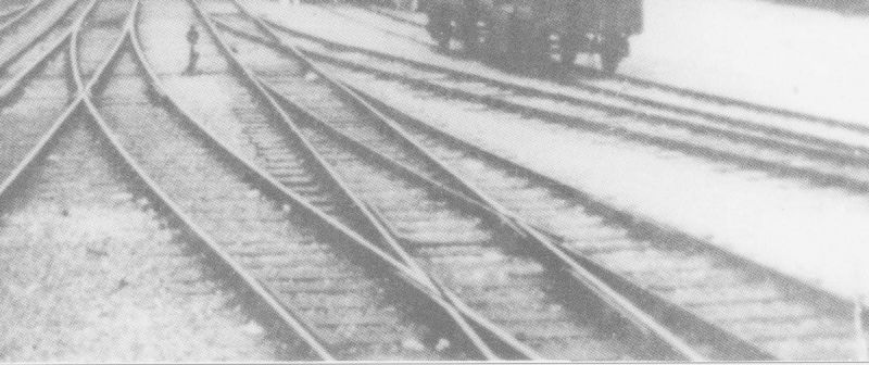 1763_301742_060000000.jpg 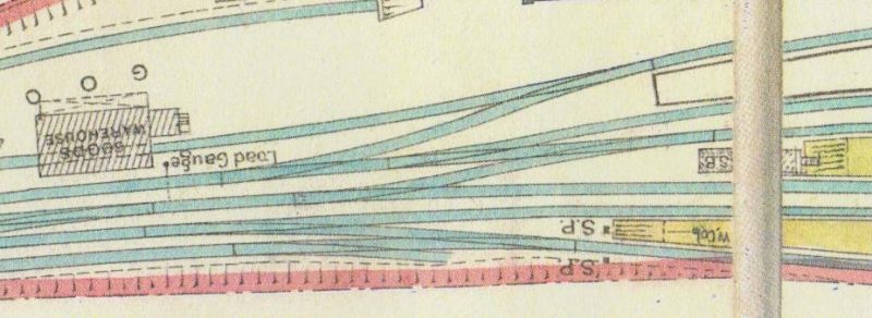 |
||
| Last edited on 1 Nov 2013 12:27 by Richard_Jones |
|||
|
posted: 31 Oct 2013 08:59 from: JFS
click the date to link to this post click member name to view archived images |
Hi Richard, I'm pretty sure that there is a requirement for a clearance here. Looking at the box diagram, the point leading to the loading dock is worked from the box (lever 15) but the point in rear of that is a hand point, thus, this point is the only means of providing protection for traffic entering the Down Loop against errant shunting movements. But it must have been a pretty minimum clearance - no LMS Duchesses or GW 70 footers permitted! Cheers, Howard |
||
| Last edited on 31 Oct 2013 09:00 by JFS |
|||
|
posted: 31 Oct 2013 11:34 from: Richard_Jones
click the date to link to this post click member name to view archived images |
Hi Howard, Although I think there may be "clearance", it may be minimal. Although I think I could have done this with the "rolling vehicle" in Templot, but have tried it practically (see photo below!) on the templates (as panic sets in before construction proceeds too far!) As you say lever 15 from North Box operates the point between the bay and down loop but I wonder if ground signal (24) is interlocked with crossover (20) for movement even into the dock? I don't have a locking diagram, and am in two minds what to do with the actual layout - I am quite tempted to have a mechanical frame (for most of the points) with no interlocking at all (as per "Ferring") best wishes Richard undefined |
||
|
posted: 31 Oct 2013 12:58 from: JFS
click the date to link to this post click member name to view archived images |
Hi Richard, Nice picture! On thing is for sure, it is a bit late to alter the Template!! We are to some extent guessing without the locking diagram, but "convention" would have it that signal 24 would only clear with 15 R and 20 N (ie for a movement into the Down Loop. Shunt moves into the dock would pass it at danger. The protection requirement can only be provided by points - in this case, 20 cannot be pulled with 15 R. Even though the clearance is minimal, this gives "protection" within the meaning of the act bearing in mind that "protection" can be provided by means of a trap point spilling an errant vehicle onto the ballast with who-knows-what resulting clearance. Probably the Board of trade accepted this arrangement on the basis that shunting would not be allowed to take place whilst a train was entering the loop (which only happened on 5 days a year after all!) though I am puzzled why it is necessary given the spaciousness of the layout. Possibly your curving things has made it a bit tighter than the real thing and it might look a tiny bit odd, but it can be argued that it is not "wrong" Hope that saves you scrapping any track! Best wishes, |
||
|
posted: 31 Oct 2013 23:43 from: Richard_Jones
click the date to link to this post click member name to view archived images |
Hi Howard, I don't think that the track layout was the company's original intentions as I have an old OPC track plan, which was probably a "design proposal" as it doesn't have the link to the down loop, or from the goods shed road into the further loading dock road (and other differences, though the "main" tracks look to be in the right place) Given the Brighton's liking for 3 way points perhaps they could have taken both loading dock roads from the further point which would have maintained the double track spacing. Still trying to work out what all the dimensions on this drawing relate to! best wishes Richard 1763_311838_000000000.jpg 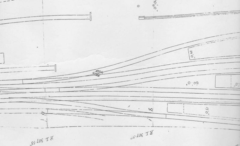 |
||
|
posted: 1 Nov 2013 10:48 from: JFS
click the date to link to this post click member name to view archived images |
Interesting! Perhaps the drawing was a submission to the BoT hence so few but significant dimensions - but only a guess! Of course, the omissions could just be a draughtsman's oversight - particularly if the drawing was for other purposes. Best wishes, Howard |
||
|
posted: 1 Nov 2013 14:32 from: Martin Wynne
click the date to link to this post click member name to view archived images |
Richard_Jones wrote: Hi Martin,Hi Richard, Can you clarify what you are asking me? I'm struggling to follow the discussion with Howard. Which is the loading dock? Which is the first bay line? Which is the second bay line? Neither of your maps comply with the Board of Trade spacing rules, although the photo appears to do so. You can't have multiple running lines at 6ft way. Sidings, loops and slow lines must be spaced at 10ft way (or 9ft way in special cases) from a pair of main lines which have 6ft way. Thus is for the safety of staff on the ground, and clearance for signal posts, etc. This rule produces the classic alternating wide and narrow spacings, as seen for example on the cover of David Smith's GWR track book: cvr_track_400px.jpg  The spacing-ring tool in Templot is intended for setting/checking clearance between tracks. Clicking the set-ring: > p-s button pre-sets it to the required diameter for 11ft-2in track centres (6ft way) at the current gauge and scale. For EM that means 24.63mm between the rails. For 10ft way you then add on 4ft (16mm) making 40.63mm. There is 6ft way clearance at position 1 on your plan, but clearly a significant conflict at position 2: 2_010919_410000000.png 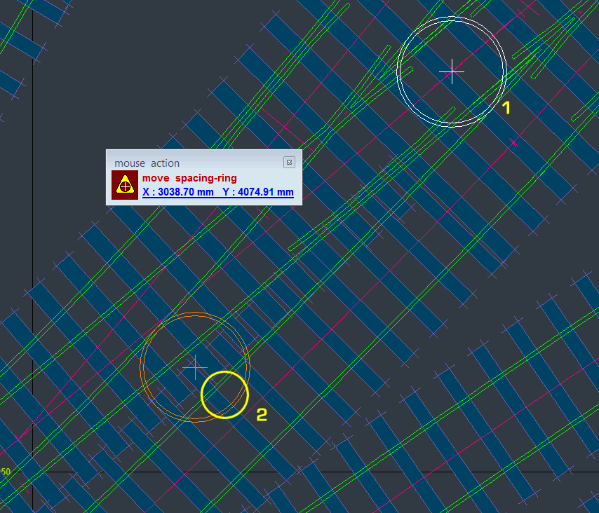 I think that if you increase the the loop line(s) spacing to at least 9ft way from the main lines, this problem will be avoided. I'm sorry I can't do any more Templotting today, so I will have to leave it there. regards, Martin. |
||
|
posted: 1 Nov 2013 20:00 from: JFS
click the date to link to this post click member name to view archived images |
Hi Martin, Very sorry we got a bit into an internal discussion there - we both know the real thing! Just to mention that of course, everything you say is spot on - however, in this case, these are not running lines in that sense and movements cannot normally take place simultaneously on them. however, one is required to provide flank protection for movements on the other and for that, the spacing shown in the original drawing seems insufficient. drawing Best wishes, Howard. |
||
|
posted: 2 Nov 2013 00:18 from: Richard_Jones
click the date to link to this post click member name to view archived images |
Hi Martin and Howard, First apologies Martin, not only have I not put the names on the labels, but in the conversations I have not been consistent in the names I used, viz: bay and dock! Anyway your reply has been helpful, in that I do think I need to get that 6', as you demonstrated with the spacing ring consistent down the two "rather close" lines (89 & 85) - I think it is down to the angle that the line comes off the down loop point (86) and the geometry/position of (85) that kicks back into the loading dock, so I think it is just down to me to tinker with the templates till they look better. I have also scanned in the original "straight" colour map to check the spacing of the lines at various points - I should have done this some time ago! (though I am not entirely sure of its scale, but looks to be 1:1500) Again though I think my process of curving the whole lot has complicated either the geometry, or my ability to interpret how to reproduce it! Thanks for you help - have a relaxing weekend (away from Templot?) enjoying some fireworks! best wishes richard |
||
|
posted: 3 Nov 2013 17:53 from: Richard_Jones
click the date to link to this post click member name to view archived images |
Hi Howard and Martin, I have a "play about" with a scan of the "un-tampered" plan, and have come to the conclusion that there wasn't adequate clearance on the real thing! However it has thrown up another dilemma as to whether I should build the layout "to plan" or as my "curved version" - without fiddle yard (or return curves) I would need 23', but then wouldn't be able to run the layout at home..... I shall have to end up with a "compromise" on the track layout in that area which looks as close as I can get it to the photos. best wishes Richard |
||
| Attachment: attach_1674_1010_Singleton_Straight_1_1.box 295 | |||
|
posted: 3 Nov 2013 17:54 from: Richard_Jones
click the date to link to this post click member name to view archived images |
shape file for "straight version" |
||
| Attachment: attach_1675_1010_colour_straight.bgs 475 | |||
|
posted: 3 Nov 2013 23:03 from: Richard_Jones
click the date to link to this post click member name to view archived images |
Hi Martin Sackcloth and ashes time...... My only excuse is that it was probably a feature of the newer version of Templot, but "Modify shape" "wrap along control template" is absolutely brilliant In my further "tinkering" I have just wrapped that original plan along the 15' curve template through the station and it works a treat..... now to see if that helps me resolve my layout design best wishes Richard |
||
|
posted: 4 Nov 2013 00:37 from: Martin Wynne
click the date to link to this post click member name to view archived images |
Richard_Jones wrote: "Modify shape" "wrap along control template" is absolutely brilliantHi Richard, I'm glad you found it useful. For anyone else, the full words and music are at: http://templot.com/companion/index.html?wrap_picture_shape_to_curve.htm regards, Martin. |
||
|
posted: 6 Nov 2013 12:34 from: Richard_Jones
click the date to link to this post click member name to view archived images |
Hi All, An interesting learning lesson - having had trouble with clearances on the layout I tried using TEMPLOT on the actual layout - too big for my available space and although all the turnouts were larger than on my original plan, when transferred to my compressed/curved layout they (in my opinion) look and fit better, albeit with the 6' being slightly challenged in the same area, but not to the extent of the previous version. Yes, I will have to scrap some timbers and rivets, but still cheaper than being unhappy with it after it is all built! best wishes Richard |
||
| Attachment: attach_1683_1010_Singleton_Final_3_1.box 405 | |||
| Last edited on 7 Nov 2013 18:32 by Richard_Jones |
|||
|
posted: 3 Jan 2014 16:16 from: Richard_Jones
click the date to link to this post click member name to view archived images |
Hi All, Hope you had a Happy Christmas and New Year. I couldn't resist the temptation to "play trains" a bit, so below is a picture of a ballast train leaving the down loop (in the wrong direction!) - I think it would have had a larger loco than an A1 on such duties, but its the only loco anywhere near finished! (ballast brake and wagons - 5&9 Models, Terrier - Westward kit) Looking at photos of the prototype, there is a distinct reverse curve into the down loop, so I think I need to move that point further back, as increasing the ruling curvature through the station has resulted in it being almost straight. Also, I appear to have the platforms too wide, so some "tweaking" will be necessary on TEMPLOT before track is actually laid . Best wishes for a successful year of modelling in 2014 Richard1763_031114_300000000.jpg 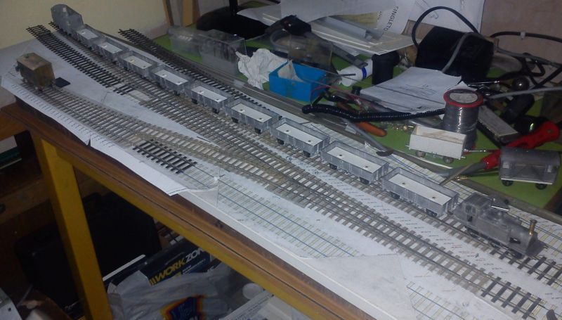 |
||
|
posted: 6 Jan 2014 12:08 from: Richard_Jones
click the date to link to this post click member name to view archived images |
Hi Martin, Can I pick your brains on transition curves? - as I mentioned in my previous message I'm indicated I was going to "tweak" the curve between the down main and down loop which is formed by template 87 - I've also moved the turnout (86) forward and used the "s curve transition" on 87, without knowing what I'm actually doing (!!!) - but this looks a bit better, even if I'm not convinced of the alignment between 86 & 87! I know the photos of the actual station may give a false impression due to foreshortening, but is there anything else you can suggest to improve things, accepting that I've already distorted the geometry by constraining it to a constant radius through the station? many thanks Richard 1763_301735_340000000.jpg  1763_301735_000000000.jpg 1763_301735_000000000.jpg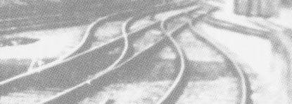 |
||
| Attachment: attach_1706_1010_Singleton_Final_4_1.box 421 | |||
|
posted: 6 Jan 2014 16:33 from: JFS
click the date to link to this post click member name to view archived images |
Hello Richard, Just had a look - v nice! But that is quite dog leg there. I was thinking that if you made 66 a 1:9, the alignment is much better. I had a play - it is not finished, but it shows what I mean. Cheers, Howard |
||
| Attachment: attach_1707_1010_Singleton_HB.box 458 | |||
| Last edited on 6 Jan 2014 16:34 by JFS |
|||
|
posted: 11 Jun 2016 19:28 from: Richard_Jones
click the date to link to this post click member name to view archived images |
Hi All, progress has slowed somewhat - photographs of the turntable are still illusive, but a selective scan of one of the Bannister photographs has revealed the edge of the pit, indicating, I think, that it was not a boarded table. I am waiting on a copy of a drawing from Carlise Records office for a 45' Cowan & Sheldon turntable 1763_111420_290000001.jpg 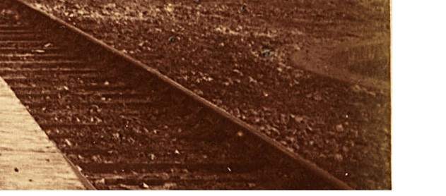 I have just "found" a mechanism that I acquired many years ago to use on a turntable, not envisaging it would be for a model of Singleton.1763_111420_280000000.jpg 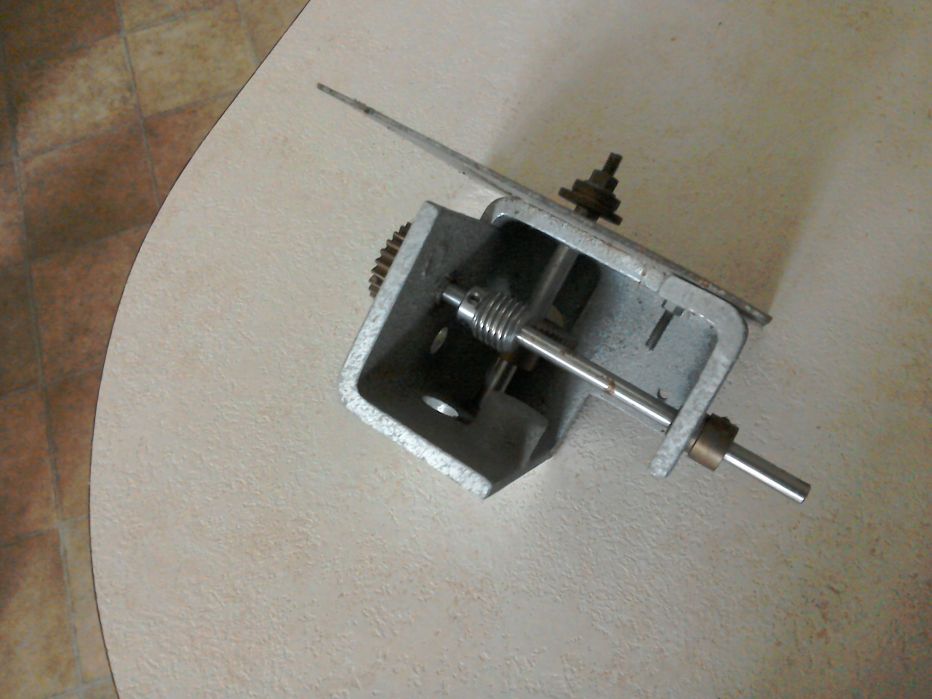 best wishes Richard |
||
|
posted: 4 Feb 2017 22:59 from: Andrew Duncan
click the date to link to this post click member name to view archived images |
Hello RichardAny news of your progress.....? Kind regards Andrew |
||
|
posted: 4 Feb 2017 23:13 from: Richard_Jones
click the date to link to this post click member name to view archived images |
Hi Andrew, I'm afraid there's not been much progress recently - all of the track is built, but the sticking point is clearing the garage so that I can get on with the serious woodwork for the baseboards. I also have a large backlog of suitable stock awaiting the paint shop, and have distracted myself with a 7mm mini layout..... Best wishes Richard |
||
|
posted: 5 Feb 2017 21:24 from: Andrew Duncan
click the date to link to this post click member name to view archived images |
Hello Richard The mini 7mm sounds interesting. What's that all about? Andrew |
||
|
posted: 5 Feb 2017 23:12 from: Richard_Jones
click the date to link to this post click member name to view archived images |
Hello Andrew,I am afraid I succumbed to temptation and bought myself a Dapol KESR Terrier in O gauge, which in turn led to a Steam and Things Pickering steam railcar kit! So an Edwardian era KESR layout is in the offing using a couple of baseboards salvaged from an earlier 4mm excursion...... Best wishes Richard 1763_051808_350000000.jpg 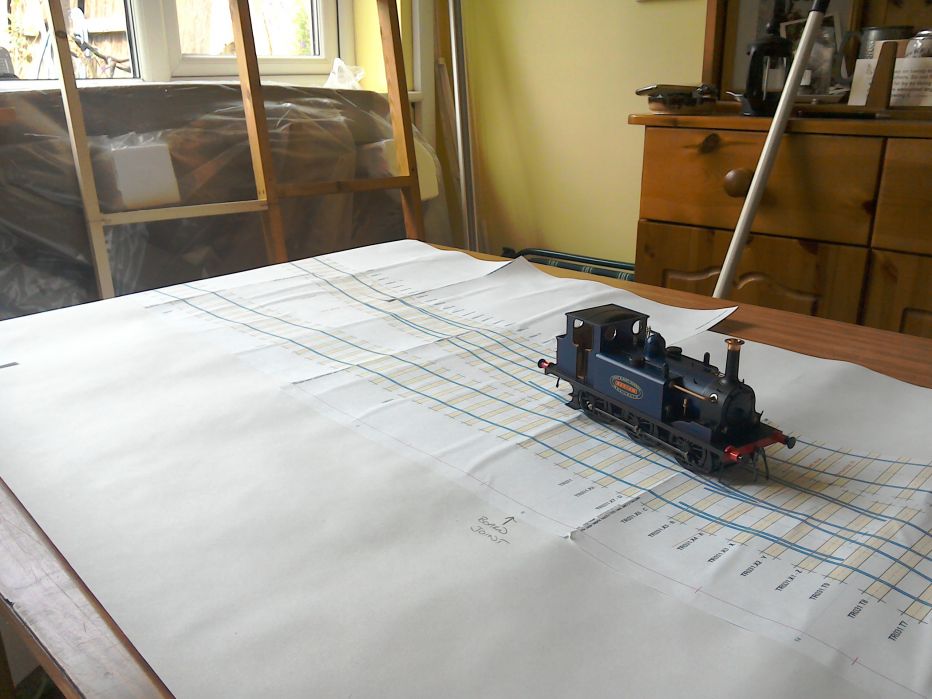 1763_051812_090000000.jpg 1763_051812_090000000.jpg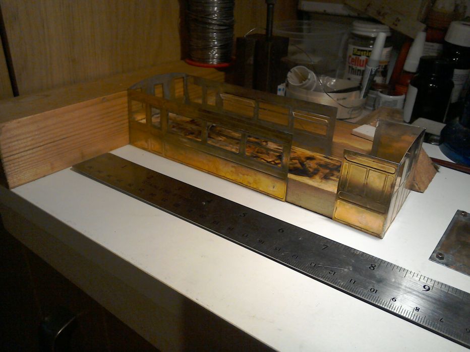 |
||
|
posted: 7 Feb 2017 02:10 from: Andrew Duncan
click the date to link to this post click member name to view archived images |
Hello Richard Thanks for the reply and the pictures, the Terrier looks lovely and the steam railcar rather interesting and nicely built so far. Hope you'll post more on the project as time and progress allows. Kin d regards Andrew |
||
|
posted: 24 Mar 2017 21:31 from: Richard_Jones
click the date to link to this post click member name to view archived images |
I believe the shape file might have been corrupted (or I uploaded the wrong one!) - kept getting "empty" pictures, so here's one that I know works (or did when I created it!) |
||
| Attachment: attach_2398_1010_Singleton_curved_colour_v2.bgs 313 | |||
|
posted: 24 Mar 2017 21:59 from: Martin Wynne
click the date to link to this post click member name to view archived images |
Hi Richard, You need to upload also the SK81 file from the same folder. The BGS file contains only the position and size of the picture shape(s). The actual image is contained in the SK8n files (one file for each picture shape). regards, Martin. |
||
|
posted: 24 Mar 2017 22:28 from: Richard_Jones
click the date to link to this post click member name to view archived images |
Oo-er, Thanks Martin, I think I have just demonstrated how little I understand TEMPLOT, and probably why I kept getting "empty" pictures! best wishes Richard |
||
| Attachment: attach_2399_1010_Singleton_curved_colour_v2.sk81 318 | |||
|
posted: posted: 24 Mar 2017 22:59 from: Martin Wynne
click the date to link to this post click member name to view archived images |
Hi Richard, That was a rather large picture shape containing a lot of blank space, making it slow to load and zoom. Also the colour was a bit pale. Here is a version with deeper colours. I used the new crop/combine function in Templot to make it smaller and faster. It should be exactly the same size as before on the trackpad. Download both the SK81 and BGS files to the same folder, and then open the BGS file to launch Templot. regards, Martin. |
||
| Attachment: attach_2400_1010_singleton_curved_colour_shape.sk81 292 | |||
|
24 Mar 2017 22:59 from: Martin Wynne
click the date to link to this post click member name to view archived images |
And the BGS. |
||
| Attachment: attach_2401_1010_singleton_curved_colour_shape.bgs 288 | |||
|
posted: 24 Mar 2017 23:50 from: Richard_Jones
click the date to link to this post click member name to view archived images |
Martin Wynne wrote: Hi Richard,Hi Martin, Many thanks..... best wishes Richard |
||
|
posted: 21 Apr 2017 22:33 from: Richard_Jones
click the date to link to this post click member name to view archived images |
Dreaming of playing trains........ 1763_211731_510000000.jpg 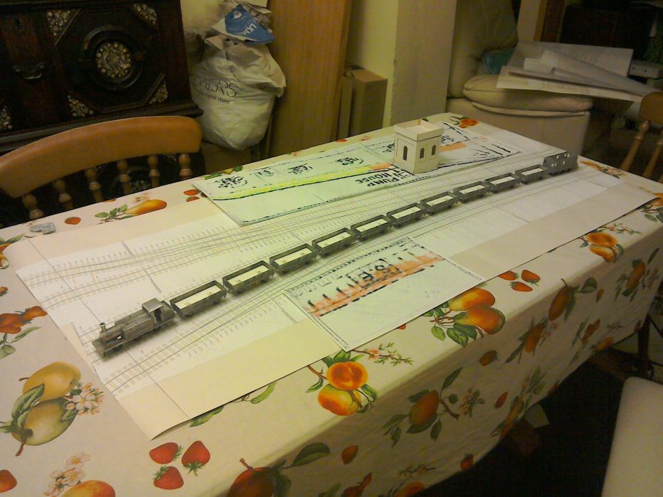 1763_211732_520000000.jpg 1763_211732_520000000.jpg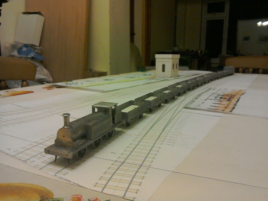 |
||
|
posted: 25 Aug 2018 14:42 from: Richard_Jones
click the date to link to this post click member name to view archived images |
Having printed out another set of templates to work on for baseboard size and positioning I decided to lay them on the floor just to check that it will fit! Yes it does, but they should be positioned nearer to the settee... As you might guess this will not be a permanent layout, but it was important to me that it could be set up at home. 1763_250936_460000000.jpg 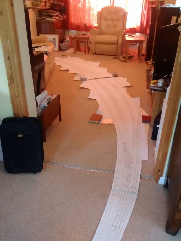 1763_250936_470000001.jpg 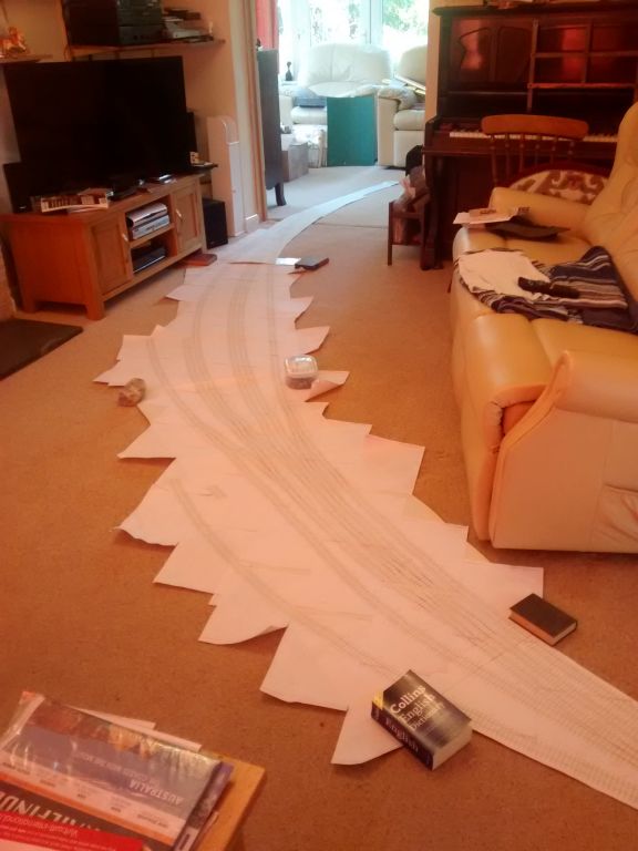 |
||
|
posted: 25 Aug 2018 15:23 from: JFS
click the date to link to this post click member name to view archived images |
All looking good Richard! Very much looking forward to the next installment. Best Wishes, Howard |
||
|
posted: 25 Aug 2018 15:30 from: Rob Manchester
click the date to link to this post click member name to view archived images |
Hi Richard, Yes, agree with Howard, looks great. Will the legs of the layout be placed to allow a view of the TV ? Rob |
||
|
posted: 25 Aug 2018 19:27 from: Richard_Jones
click the date to link to this post click member name to view archived images |
Rob Manchester wrote: Hi Richard,Is there anything worth watching on the television? |
||
|
posted: 26 Aug 2018 09:01 from: Richard_Jones
click the date to link to this post click member name to view archived images |
with hindsight (!!!) I should have shown the templates with the point work laid on top.... so just the plain track (and the baseboards!) to build... 1763_260355_250000000.jpg 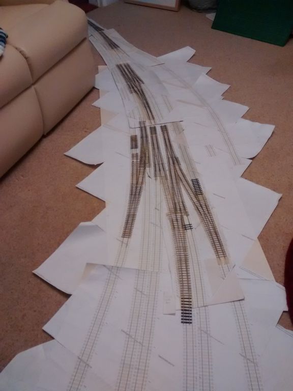 the north end of the station - goods yard to the right, middle distant. 1763_260355_260000001.jpg 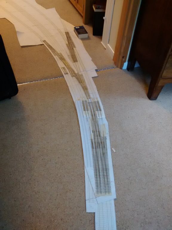 southern end of the station - turntable will be just beyond the book holding the templates flat! |
||
|
posted: 26 Aug 2018 11:26 from: Andrew Duncan
click the date to link to this post click member name to view archived images |
Hello Richard, Great to see you're at it again. I didn't realise that you'd already built all the point work, it looks very good indeed. Are you building the plain track from scratch or using flexi track? But perhaps more to the point, what design are you using for the baseboards? I recall we had a brief exchange about baseboards this time last year but I don't think I'd understood what your plans are? I'll look forward to seeing you're progress with great interest, I love the sweeping curves of the pointwork. Kind regards Andrew |
||
|
posted: 12 Aug 2019 13:10 from: Richard_Jones
click the date to link to this post click member name to view archived images |
Hi All, As posted in "Off Track" it has been very helpful to find that the drawings previously in the plan arch at Waterloo are now available via Network Rail archive. The general website address for the archive is: http://www.networkrail.co.uk/who-we-are/our-history/the-network-rail-archive/ and the Singleton drawings listed can be viewed at: http://nr.printstoreonline.com/stations/singleton-stations/ in particular these have enabled me to develop a drawing for the platform buildings (demolished mid to late 50s) though they cannot be taken as 100% accurate and clearly the brick layers etc used the drawings as a "general guide". I will work through those drawings for extant buildings to produce "as built" drawings, starting with the gent's toilet block. best wishes Richard |
||
| Please read this important note about copyright: Unless stated otherwise, all the files submitted to this web site are copyright and the property of the respective contributor. You are welcome to use them for your own personal non-commercial purposes, and in your messages on this web site. If you want to publish any of this material elsewhere or use it commercially, you must first obtain the owner's permission to do so. |
