Templot Club Archive 2007-2020
|
|||
| author | remove search highlighting | ||
|---|---|---|---|
|
posted: 8 Sep 2010 17:15 from: Brian Nicholls
click the date to link to this post click member name to view archived images |
Hi All, Can anyone please advise me as to what the maximum width of timbers were used on the real (prototype) railway ? In particular related to the L & NWR or LMSR or MR track-work, any time between 1880 - 1940. I know the standard sizes usually used are, 10” and 12” width timbers, but would like to know the max. ever used. The reason for my question is, that I have, in several places, two adjacent Vee’s + wing rails and the timbers do not quite line up and are awkwardly angled to each other. The solution would be to use a single, but much wider, timber at a nominal angle between the two Vee’s, and the same for the wing rails. Now I could just put wider timbers in to finish the job, but I do not want to contravene prototypical standards. Best regards. Brian Nicholls. |
||
|
posted: 8 Sep 2010 17:53 from: Martin Wynne
click the date to link to this post click member name to view archived images |
Brian Nicholls wrote: Can anyone please advise me as to what the maximum width of timbers were used on the real (prototype) railway ?Hi Brian, The normal width of crossing timbers is 12". It was quite common for 14" timbers to be used under V-crossings and K-crossings where the chairing requirements made it necessary. Wider timbers up to 18" wide were occasionally used, but only where strictly necessary. For example some early switch-diamonds had a single central 18" timber supporting both sets of blade tips. Later designs used two ordinary timbers closely spaced, for economy and ease of handling. Sorry I can't tell you the widest timber ever used, I doubt that anyone can. The widen button on the shove timbers dialog increases the width in 2" steps. regards, Martin. |
||
|
posted: 8 Sep 2010 18:37 from: Brian Nicholls
click the date to link to this post click member name to view archived images |
Martin Wynne wrote: The normal width of crossing timbers is 12".Hi Martin, Many thanks for your quick response. I will try using the 14” and/or 18” widths to see how things fit. I have a suspicion, that at New Street many things related to the track-work there had to be “Crafted” to fit due to the historical evolvement of the station. Track layouts and formations at the station were very tight and confined. This was caused by the severe restrictions and limitations of the civil engineering, in particular, the exit/entrance tunnelling, when the station was first built and opened in 1854. Then when the Midland Railway came along a decade or two later, the same civil engineering restrictions still applied, so the MR had to make a very curved station, on their side, and join into the LNWR track-work at the London (Eastern) end of the station. They, the MR, did however, get a concession to make another tunnel at the Western end which had to be very close and next to the original LNWR tunnel. Also because of breakdowns in the early days MR insisted on joining into the LNWR tracks at the western end so that they, and the LNWR traffic could bypass areas of the station as and when required. In all, this made the track layout of the station very tight within the limited space available and many complex formations to interleave all the platform and sidings roads, which converged at either end of the station, just before disappearing into the under city tunnels. Having said all that, although I have no evidence to back me up, I would not have been surprised to find that the ‘gangers’ did use “none standard” materials and procedures to accomplish what was required at the time. Thanks again for the information Martin, as I stated above I will see what wider timbers look like and how well they fit in. All the best. Brian Nicholls. |
||
|
posted: 9 Sep 2010 11:56 from: richard_t
click the date to link to this post click member name to view archived images |
The CLC/LMS 4-way I posted in the share and show section, has two 12" timbers side by side in two places. The timbering is from the official drawing, for a replacement for the existing formation. | ||
| Last edited on 9 Sep 2010 11:56 by richard_t |
|||
|
posted: 9 Sep 2010 14:21 from: Brian Nicholls
click the date to link to this post click member name to view archived images |
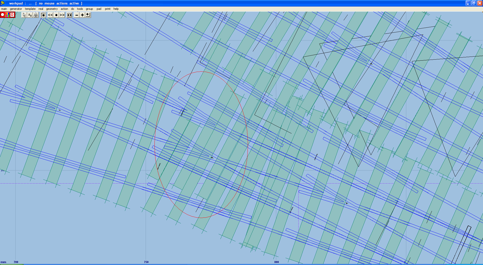
richard_t wrote: The CLC/LMS 4-way I posted in the share and show section, has two 12" timbers side by side in two places. The timbering is from the official drawing, for a replacement for the existing formation.style="BACKGROUND-COLOR: #f8fcff"Hi Richard, Thank you kindly for your response to my query. I have just looked again at your posted CLC/LMS 4-way and can only see a couple of places where side by side timbers are used, and in those cases, they are there, it would seem, to fill in gaps at awkwardly spaced timbers. The two adjacent Vee’s that you have in the formation, fit nicely onto a single 12” timber which is slightly angled. In my case, the Vee’s are a little more out of alignment, and trying to use a single timber at a more severe angle does not help the timbering around that area. See JPEG file below, the area where the Vee’s are, is circled in red. (also see my Posting of My First attempt at Templotting for Bham New Street.) I think I understand what you mean by using side by side timbers, in order to make up the width, the equivalent of 24”, however, with the position of the Vee’s in my case, I would consider that in the real railway world the gangers would have to be cautious of the chair fixing screws (Blots) may fall into the side by side gap (join) where the two timbers come together. This may then lead to a weak chair fixing at that point and the inspectors may not allow this. I also have been looking at many photographs of various parts of track-work and have spotted some quite abnormal fixings of timbers, just to fit things in and maintain the integrity of the formations. It is unfortunate, that there are no photographs or official drawings of my formation as, apparently most, if not all such drawings were destroyed in the Blitz during WW2. As you can see from the attached JPEG file, I have been trying several things to get around this problem. All the best. Brian Nicholls. |
||
| Attachment: attach_863_1236_Vee_Sample_ScreenShot.jpg 297 | |||
|
posted: 9 Sep 2010 14:34 from: Brian Nicholls
click the date to link to this post click member name to view archived images |
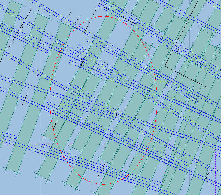
Hi All, Apologies about the large (loud) picture included in my last message, I picked up the wrong original screen shot file. Should have been the one shown below. All the best. Brian Nicholls. |
||
| Attachment: attach_864_1236_Vee_Sample_ScreenShot-S.jpg 184 | |||


| Please read this important note about copyright: Unless stated otherwise, all the files submitted to this web site are copyright and the property of the respective contributor. You are welcome to use them for your own personal non-commercial purposes, and in your messages on this web site. If you want to publish any of this material elsewhere or use it commercially, you must first obtain the owner's permission to do so. |