Templot Club Archive 2007-2020
|
|||
| author | remove search highlighting | ||
|---|---|---|---|
|
posted: 9 Feb 2011 12:10 from: Gordon S click the date to link to this post click member name to view archived images |
Hi Guys, I'm considering building a 2.6m diameter helix and have mapped all the trackwork out with tracked edges to enable me to machine cut 12 pieces to build one complete circle. I found the menu item 'swing angles' and set that to 30 degrees and that seems fine, but it hasn't added the lines from the centre to enable me to accurately cut the segments. At present I've simply drawn the lines across the template using the ends of the track bed edges as a guide. Is there a way of adding the radial lines to make accurate segments? You only need to be a fraction out on each of 12 pieces to find you have not made a true circle. |
||
|
posted: 9 Feb 2011 13:11 from: Martin Wynne
click the date to link to this post click member name to view archived images |
Gordon S wrote:Is there a way of adding the radial lines to make accurate segments?Hi Gordon, Use the drawing pen attached to the spacing-ring tool. This creates lines in your background shapes. 1. Put notch at one end of line. 2. Jump the spacing-ring to the notch. 3. Move/draw the pen to the spacing-ring. I've quickly made a bit of Jing video -- sorry it's so scruffy, ignore the mistake in the middle. Allow a few seconds to download. Zoom in closer when you try it, so that you can actually see the notch and the ring. regards, Martin. |
||
|
posted: 9 Feb 2011 13:26 from: Martin Wynne
click the date to link to this post click member name to view archived images |
p.s. Gordon, If you need longer lines extending beyond the track ends, make double-track outside your curve. Draw to that template, then delete it. There are other ways of doing the same thing. For example you could peg dummy centre-line-only straight templates at each end of your curve, and then rotate each one by 90 degrees. They should intersect on the radial centre, and you can adjust the lengths of each using F4. You can change all the printed line thicknesses at print > printed line thicknesses > set any . Martin. |
||
|
posted: 1 Mar 2011 10:06 from: Gordon S click the date to link to this post click member name to view archived images |
Hi Martin, thanks for that. I've generated the segment lines without problem and they'll provide perfect cutting guides, but somehow or other I've managed to move the eight lines off the plan and now need to put them back on the radial centre. I've been into backgound shapes amd move all, but it is asking for a dimension. So, a couple of questions. How do I work out how far to move the lines back to the radial centre notch or is there a simple way to pick them up and move them. Is there a 'place shape on notch' command or something similar that will allow me to pick up the eight background shapes and move them back to their original position? |
||
|
posted: 1 Mar 2011 11:26 from: Martin Wynne
click the date to link to this post click member name to view archived images |
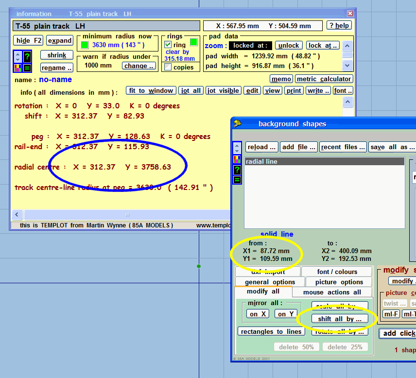
Gordon S wrote:How do I work out how far to move the lines back to the radial centre notch or is there a simple way to pick them up and move them. Is there a 'place shape on notch' command or something similar that will allow me to pick up the eight background shapes and move them back to their original position?Hi Gordon, Sorry, there aren't any commands to move shapes that way. You will need to calculate the move yourself, or do it manually by mouse action. Also, you can only move a single shape, or all of them at once, so save a BGS file first if there are other background shapes on your plan. Then delete all the shapes except the ones you want to move. You can then add the file back later (add file...), after the move. The easiest way to move them is by mouse action, and if these are lines for cutting wood that should be plenty accurate enough. action > mouse actions: shapes > shift all shapes menu item. Zoom in fully and position the lines over the radial centre mark. If you prefer the accuracy of calculation, the X,Y co-ordinates of the line ends are shown on the background shapes dialog below the list box. Assuming all the lines terminate at one centre point, find the common X,Y end co-ordinates for all of them. Then find the radial centre for the track template, which is shown on the expanded information panel: 2_010551_430000000.png  You must then calculate the shifts required, click the shift all by... button, and enter the calculated dimensions. Post all the figures here if you need more help. p.s. how did you manage to move them all out of position in the first place? regards, Martin. |
||
|
posted: 1 Mar 2011 12:53 from: Gordon S click the date to link to this post click member name to view archived images |
Well......The lines weren't long enough and I was trying various commands to lengthen them all in one operation. From memory I tried modify all and then scale by...Random thought said scaling by 120% might make the lines longer.. Pressed the button and whoosh, they shot across the page and the rest is history. Thanks for your reply. I thought I could probably move them with a mouse action, but couldn't fathom out the command. Picked up on your tip re double track though and that lengthened the lines no problem. Just out of interest I'm building a complete circle to be used as a roundabout..You can enter at ony one of four points and leave on any other one. This gives me both a reverse loop and a dumbell loop in one simple circle. Woodwork wise I'm building an octagon, to take the circle as the finishing saw will give a much better finish in straight sections than a jigsaw cut curve. Once the angles are accurately cut, it will all bolt together. This will also double as a test track/running in circle whilst work in other areas progresses. |
||
| Last edited on 1 Mar 2011 12:54 by Gordon S |
|||
|
posted: 1 Mar 2011 13:52 from: Martin Wynne
click the date to link to this post click member name to view archived images |
Gordon S wrote: Random thought said scaling by 120% might make the lines longer..Hi Gordon, Scaling a shape scales the grid co-ordinates, so the shape moves further from the grid origin as well as getting larger. However, you could have undone the scaling by repeating it with the inverse -- i.e. to undo scaling by 120%, scale by 83.33%. ( 100 / 120 = 83.333333... ) Your circular woodwork sounds interesting, photos please when it's done. Martin. |
||
|
posted: 2 Mar 2011 11:25 from: Gordon S click the date to link to this post click member name to view archived images |
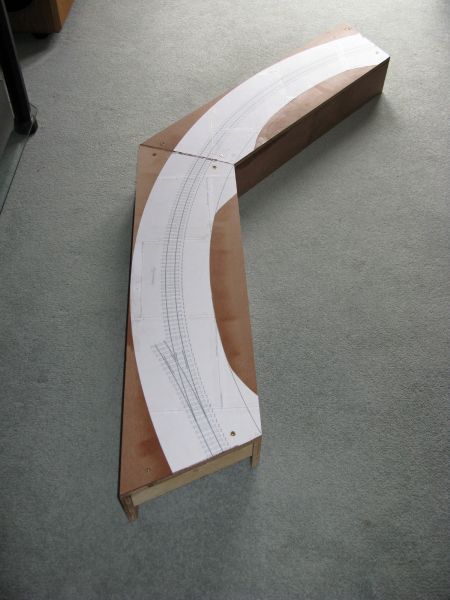
OK, I think I've cracked it... Once again the use of Templot has proved to be invaluable. The 964mm (38") radius circle has been drawn up with the sector lines in place. The templates were stuck down onto the 12mm ply and the angles accurately cut to form the octagon. The side rails are 100mm deep so they provide protection for the Tortoise point motors and are also made from 12mm ply. This forms a true surface and one that will not warp over time. I've used 45 x 45 blocks in each end which will be used to house alignment dowels and securing bolts. To save bending, I will lay cork underlay over the track base and then use 5mm self adhesive copper strip to form a top surface mini bus around the loop. I will take wires from each piece of rail to the copper strip and then just two connections to the main bus of 4mm copper. It was a doddle to cut each strip straight on the bench saw and then cut all the 22.5 degree angles. Saves all the messing about with a jigsaw and gives a much better finish. All of this loop will be hidden, so surface wiring is not an issue and will provide much relief from the old back pain.... 479_020624_410000000.jpg  |
||
| Last edited on 2 Mar 2011 17:47 by Gordon S |
|||
|
posted: 2 Mar 2011 12:51 from: Raymond
click the date to link to this post click member name to view archived images |
A cork underlay will make for a noise board. Why not try Brian Lewis's method of foam underlay fixed with latex and then latex your track onto that? That way you ar emore likely to hear the clackety clack of the wheels too. Regards Raymond |
||
|
posted: 2 Mar 2011 13:03 from: Gordon S click the date to link to this post click member name to view archived images |
Thanks for the tip Raymond. I'll take a look at it, but to be honest, I'm not a fan of any foam underlay. In this case, cork will be fine as it is stuck to the template and the paper acts as an insulator. The track is then stuck to the cork strip with no track pins to transmit noise through to the ply surface. This loop is hidden from view and as such will not be ballasted. Where you do have a problem with cork, is generally where the track has been ballasted to form one solid block and it is that which transmits track noise and vibration through to the ply trackbed. I'll post another pic once all eight pieces are finished. The next two are well under way as I type. I'm just waiting for the glue to dry... |
||
|
posted: 2 Mar 2011 17:20 from: Glen Suckling
click the date to link to this post click member name to view archived images |
Raymond wrote: A cork underlay will make for a noise board. Why not try Brian Lewis's method of foam underlay fixed with latex and then latex your track onto that? That way you ar emore likely to hear the clackety clack of the wheels too. I use half inch "Homosote" (a low density fiberboard) between the ply and the cork with everything glued together, not nailed or pinned. This seems to provide excellent soundproofing. Glen |
||
|
posted: 5 Mar 2011 16:12 from: Gordon S click the date to link to this post click member name to view archived images |
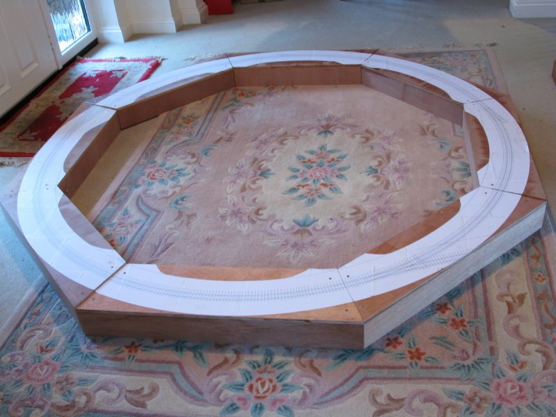
I dunno, over 50 years of modelling and all I've got to show for it is a circle of track on the carpet..... 479_051111_560000000.jpg  |
||
| Last edited on 5 Mar 2011 21:26 by Gordon S |
|||
|
posted: 5 Mar 2011 17:59 from: JFS
click the date to link to this post click member name to view archived images |
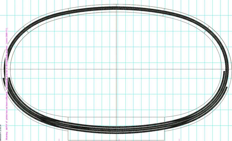
Hello Gordon, Many thanks for this topic - I learnt a lot from it which was very helpful as I was thinking about a similar project... 1129_051250_380000000.jpg  Nice carpet! Many thanks, Howard. |
||
|
posted: 5 Mar 2011 19:17 from: Nigel Brown click the date to link to this post click member name to view archived images |
Gordon S wrote: I dunno, all those years modelling and I've ended up with is a circle of track on the carpet.....Gordon Don't think it's quite complete; you've missed out the third rail! It is Hornby Dublo, isn't it? Nigel |
||
| Please read this important note about copyright: Unless stated otherwise, all the files submitted to this web site are copyright and the property of the respective contributor. You are welcome to use them for your own personal non-commercial purposes, and in your messages on this web site. If you want to publish any of this material elsewhere or use it commercially, you must first obtain the owner's permission to do so. |