Templot Club Archive 2007-2020
|
|||
| author | remove search highlighting | ||
|---|---|---|---|
|
posted: 21 Feb 2011 23:22 from: Rob Manchester
click the date to link to this post click member name to view archived images |
Hello, I have been building some common crossings ( 1:6 mainly ) using Templot templates to use as building blocks for a new layout project. I am working in P4 and using PCB timbers with code 75 BH. I use the common method of making the V and soldering this to the timbers then adding the wing rails ( straight edge/flangeway gauge for the first straight one and flangeway gauge/human eyeball for the second) and I notice that the bends in the wing rails are often not in line on the resulting crossing. The templates I am using do have them in line and some of my books mention that they should be. Anyone any ideas ? A test wagon runs OK through the crossing on either track. Thanks Rob |
||
|
posted: 22 Feb 2011 17:17 from: Martin Wynne
click the date to link to this post click member name to view archived images |
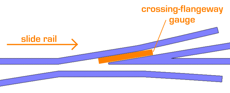
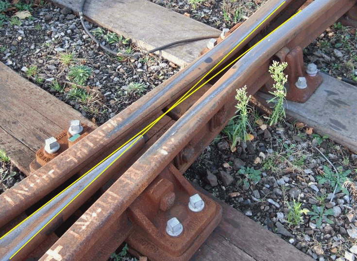
Rob Manchester wrote:I notice that the bends in the wing rails are often not in line on the resulting crossing.Hi Rob, Do you mean the knuckle bends in the wing rails are not opposite each other? Before adding the wing rails, check that the vee nose is correctly gauged from the stock rails, and equidistant between them. Then make sure that the angle of the bend in the wing rail exactly matches the crossing angle on the vee. Check by sliding the wing rail through the gauge tools up against the vee and seeing that it is properly flush against the side of the vee. Adjust the bend as necessary. Then slide the rail back just far enough to drop in the crossing-flangeway gauge strip without force but also without any freedom: 2_221146_430000000.png  If you do both wing rails this way, the knuckle bends should align. The templates show the knuckle bend as a sharp bend, but it doesn't need to be sharp. Many prototype designs have a radiused knuckle bend, with the result that the knuckle gap is wider than the crossing flangeway. If you replicate this it will be less noticeable if the bends do not exactly align. A radiused bend also helps a lot if you are using functional chairs with the rail canted at 1:20 angle. Some modellers go to the absurd length of filing a notch in the rail to make a dead sharp knuckle bend, which is totally unnecessary and looks awful. This is what it should look like: 2_202055_480000000.png  © Mick Nicholson with thanks regards, Martin. |
||
|
posted: 22 Feb 2011 18:10 from: Rob Manchester
click the date to link to this post click member name to view archived images |
Hi Martin, Martin : Do you mean the knuckle bends in the wing rails are not opposite each other? Rob : Yes that is the trouble. Martin : Before adding the wing rails, check that the vee nose is correctly gauged from the stock rails, and equidistant between them. Rob : There aren't any stock rails at this stage in the construction process. I am trying to make the common crossing first ( the hardest part ! ). I want to have the PCB timbers on the Templot template with just the vee and wing rails soldered to it. Imagine buying a pre-soldered common crossing from Brian Lewis and just plonking that down onto the sleepers. There didn't seem much mileage in making them like Brian does with small metal strips soldered underneath ( for guys building plastic or wood based turnouts ) as the PCB timbers can perform the same function for me. Martin : Then make sure that the angle of the bend in the wing rail exactly matches the crossing angle on the vee. Check by sliding the wing rail through the gauge tools up against the vee and seeing that it is properly flush against the side of the vee. Adjust the bend as necessary. Then slide the rail back just far enough to drop in the crossing-flangeway gauge strip without force but also without any freedom. Rob : I checked the angles using the same jig I made the vee parts with as advised in the EM Gauge Society instructions. I suppose the springiness of the rail bend could lead to some error here. Martin : If you do both wing rails this way, the knuckle bends should align. Rob : We shall see next time. More care needed me thinks. Martin : The templates show the knuckle bend as a sharp bend, but it doesn't need to be sharp. Many prototype designs have a radiused knuckle bend, with the result that the knuckle gap is wider than the crossing flangeway. If you replicate this it will be less noticeable if the bends do not exactly align. A radiused bend also helps a lot if you are using functional chairs with the rail canted at 1:20 angle. Some modellers go to the absurd length of filing a notch in the rail to make a dead sharp knuckle bend, which is totally unnecessary and looks awful. Rob : I am not filing a notch in the rails you will be happy to learn. You get a little bump in the rail head ( and bottom ) when bending without a notch but this is easily removed after bending. I have used Brian's ready assembled common crossings in 7mm scale and they are excellent. The cost of them in 4mm and 7mm is the same, reflecting the fact that most of the cost is on labour rather than materials and of course you can only use the ones he sells. Thanks for the pics you included. Is the shiny wear pattern on the prototype crossing a normal one ? Back to the bench with the iron and the rails.... Regards Rob |
||
|
posted: 22 Feb 2011 18:58 from: polybear click the date to link to this post click member name to view archived images |
The common crossing assembly jig that the EMGS sell could be just the thing for you, and would enable you to build the crossing up straight onto pcb sleepers. EMGS store number 8793F (brass fret only; £2-50) or 8793 (ready assembled; £8-00). HTH Brian |
||
|
posted: 22 Feb 2011 20:05 from: JFS
click the date to link to this post click member name to view archived images |
Rob, Practice, Practice, Practice. Be prepared to make 10 and throw 4 away, until they are perfect. You have already spotted that small errors are very significant. I would not try to build a complete point until you can make perfect vees and perfect switches in your sleep - the materials are dirt cheap after all, but less than perfect components make rotten points and the frustration which results is very costly! After all, a pianist does not expect to perform Chopin until they have their scales and arpeggios under their fingers. One thing I do to make sure that crossings and wing rails are perfectly aligned is to leave the rails well over length until the whole assembly is soldered up. I then cut the rails to length with a piercing saw. example;- 1129_050750_130000000.jpg  ..but notice that I do not use pcb timbers - to me, they look awful and all-soldered track is MUCH more difficult than chaired track (for me!) Good Luck, Howard. |
||
|
posted: 22 Feb 2011 22:02 from: Rob Manchester
click the date to link to this post click member name to view archived images |
Brian, Thanks for the reminder about the Common Crossing Jig sold by the EM Society. I had seen this in their list but didn't quite understand the way it was used in conjunction with the flangeway gauge to attain the essentials of straight run from vee to wing rail and correct gap. I just re-read the Manual Sheet 1.2.1.4 and I should maybe have got one of these simple things. Just looking at a turnout I made on PCB the other day and there is not reason why the common crossing couldn't have been made on a home made jig based on the Society one. I would then use my 1.06mm PCB timbers in the slots of the jig and the flangeway gauge in the way intended. Making sure the wingrails are to a common angle is still important , as Martin insisted. Howard, Arpeggios, wow, had to look that one up ! Bet that word doesn't get used on Templot Club again this year...unless you manage to slot it in of course. You are of course correct about the practice and yes the materials are cheap. I have done C&L style wood sleepers and chairs in 7mm ( even though I cheated and got ready-assembled crossings ) and found it fine. Tried it in 4mm and it just seemed beyond my patience level, too many chairs with fingers struggling to thread them all on the rails. The original layout I was to build a few weeks back was based mainly round a harbour and industrial branch so the lack of chairs didn't matter. Only problem is every time I read a railway mag my ideas change and the layout plan becomes something else. Thank heavens for Ebay. Thanks to you both. I ... I must ... I must practice ... I must practice doing ... I must practice doing my ... I must practice doing my turnouts ... I must practice doing my turnouts in ... I must practice doing my turnouts in easy ... I must practice doing my turnouts in easy stages ... Rob |
||
|
posted: 22 Feb 2011 23:14 from: JFS
click the date to link to this post click member name to view archived images |
Ha! Ha! Ha!... .. yeah, there MUST be a market for the chap who invents a chair-putting-on tool!!! And without that it can be fiddly, though I find that the Exactoscale ones are slightly better than the C & L which sometimes suffer from a bit of flash. Changing your mind is a good way of getting practice! I can see that if you are building inset track then chairs are an unnecessary pain, and you probably don't need that many PCB sleepers either, but I do think that plastic chaired track is easier to build if you are learning the trade, as it is quite a forgiving technology - if you end up with a rail in the wrong place, you can just slip a scalpel under the chair and re-stick it (Un-soldering is never easy) And the chairs hold the rail at the right height / angle while you are soldering crossings etc. But I bet that there are MANY around here who will not agree with me! I am just about to start building my latest, so I will upload some pics, then everyone can poke fun at all my cock-ups! Good Luck, Howard. (Arpeggio = scale with holes in it...) |
||
|
posted: 22 Feb 2011 23:51 from: Rob Manchester
click the date to link to this post click member name to view archived images |
Howard, Thanks for the comments. I haven't made any progress on the track tonight, fell asleep when I came in from work and spend the time since I woke up chatting to nice chaps on railwat forums......... Just been looking at the EM Society crossing-making-jig-thingy again. Think I will do a jig tomorrow ( no jokes there surely ? ) and see how it goes. What are those turnouts called where the wing rails move over to the 'frog' to switch the direction of trains ? Bet even I could make those OK.... Cheers Rob |
||
|
posted: 23 Feb 2011 19:11 from: polybear click the date to link to this post click member name to view archived images |
JFS wrote: Ha! Ha! Ha!... I reckon there could be a market for plastic half chairs (inner and outer) that are moulded lower than standard, such that they fit rail soldered directly to pcb sleepers without being too high. Or maybe plastic chairs that will fit ply & rivet track without resorting to a dremel first... Brian |
||
| Please read this important note about copyright: Unless stated otherwise, all the files submitted to this web site are copyright and the property of the respective contributor. You are welcome to use them for your own personal non-commercial purposes, and in your messages on this web site. If you want to publish any of this material elsewhere or use it commercially, you must first obtain the owner's permission to do so. |