Templot Club Archive 2007-2020
|
|||
| author | remove search highlighting | ||
|---|---|---|---|
|
posted: 3 Apr 2011 22:16 from: Mark Leigh
click the date to link to this post click member name to view archived images |
Hi All, Try as I might I don't seem to be able to remove the transition curve markings and tie bars on P&C when I print. Basically I just want the rails...now't else! Plus more annoyingly the centre lines which I had removed prior to relocating the whole templot to get the most out of my paper has appeared back on So are there any tips on how to achieve this quickly Thanks In Advance Mark |
||
| Attachment: attach_1034_1443_eridge_mk2_wiring3.box 193 | |||
|
posted: 3 Apr 2011 23:46 from: Chris Mitton click the date to link to this post click member name to view archived images |
Hi Mark What I think you need to do is basically generator -> generator settings and untick centre-lines repeat several times to untick pretty well everything else except rails then generator -> rebuild all background which should give you the plan you want. Select pad -> hide control template (unless you actually want it showing) Then select print -> printed element options and de-select all except rails If you then print in the normal fashion, you should get what you want. I can't seem to get rid of stretcher bars, but then I can't think why you'd not want them marked. Hope this helps Regards Chris |
||
|
posted: 4 Apr 2011 03:04 from: Martin Wynne
click the date to link to this post click member name to view archived images |
Mark Leigh wrote: Try as I might I don't seem to be able to remove the transition curve markings and tie bars on P&C when I print. Basically I just want the rails...now't else!Hi Mark, Templot doesn't draw tie-bars (stretcher bars). What you see is called the switch-drive mark -- it is intended to show the position of the slot in the baseboard. Prototypical stretcher bars vary in position and number, and are not shown at present. Along with the chairing detail they may get added in a later Templot upgrade, but it will require a massive amount of prototype data to be input. At present for a general guide, refer to the excellent templates downloadable from Exactoscale. To print the rails only, you could click print > printed element options ... menu item, and de-select everything except rails. But this will still leave the transition markers, guide marks and rail joints, as I assumed most printing is for track construction purposes. If you want the rails and nothing else at all, as Chris explained you need to change the generator settings: 1. click generator > use skeleton settings menu item. This will untick most items in the generator settings. 2. to remove the remaining items: untick generator > generator settings > track centre-lines menu item, untick generator > generator settings > guide marks menu item (planing marks, etc.), untick generator > generator settings > switch-drive mark menu item (tie-bar slots). 3. the above changes will print the rails as a single gauge-face line only. If you want the normal rails printing with both rail edges: tick generator > generator settings > rails > both rail edges menu item. 4. click generator > rebuild all background to apply these settings to the entire track plan. 5. if you want both rail edges but without the solid coloured infill, select the print > printed drawing options > rail infill style > menu options. n.b. As an alternative to removing items above, for printing you can use the trick of changing their colour to white. Removing the transition markers only, came up recently: topic 1419 regards, Martin. |
||
|
posted: 4 Apr 2011 04:14 from: Martin Wynne
click the date to link to this post click member name to view archived images |
p.s. Mark, That's a very impressive wiring plan with a lot of work creating coloured partial templates. Had you done so initially, you could have removed all the track centre-lines and switch drive marks by de-selecting them in the geometry menu. Unlike the changes in my previous message these changes are saved in the .box file. That will be tedious to do now that the plan is split into so many partial templates -- it means deleting each template one at a time to the control template, making the changes, and then storing again. In the process you will lose the colours and need to re-apply them. If anyone is thinking of creating special-purpose prints like this it would be a good idea to ask here for any hints or tips before starting. There are dozens of settings in Templot and most of them are specific to each individual template, so changing an entire track plan later might be a lot of work. I'm going to add extra options to the modify on rebuild function, but a full user interface to select/de-select/change every possible setting is a nightmare as so many settings are interdependent, and some changes may disrupt existing alignments. It's much easier to know what you want in advance and make the settings on the control template as you work. regards, Martin. |
||
|
posted: 4 Apr 2011 05:35 from: Mark Leigh
click the date to link to this post click member name to view archived images |
Chris Mitton wrote: Hi MarkHi Chris Thanks, regarding the centre-lines I un-ticked them via the Generator Settings when I started the wiring diagram, then when I re-scaled from P4 to S2 they disappeared Rescaling (effectively halfing the size) was for paper saving measure.....then I noticed you can print at the end you can print at a variety of sizes but actually it seems to have worked out well as I printed out a test at 33% effectively (83% of P4) fits onto 3 A4 sheets and is legible.......well until I put the rest of the wiring info on Mark |
||
|
posted: 4 Apr 2011 05:44 from: Mark Leigh
click the date to link to this post click member name to view archived images |
Martin Wynne wrote: p.s. Mark, Hi Martin, Thanks for previous reply and the info. It may have been a lot of work but seemed easier to me than starting again as Eridge P4 was done on Templot. It only took 3hrs when I got the swing of it and with my Right Hand bandaged can't do much "proper" modeling. It was an I'm bored what can I do project hence not asking for advice sooner....didn't do much thinking at all Thanks also for the added PS as that may help as well. The colours are not finalised yet so there may be time still to get them to save to .box file Mark |
||
|
posted: 4 Apr 2011 10:33 from: Martin Wynne
click the date to link to this post click member name to view archived images |
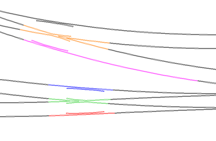
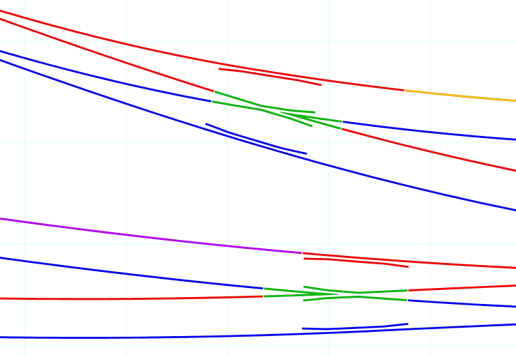
Mark Leigh wrote:Rescaling (effectively halfing the size) was for paper saving measure.....then I noticed you can print at the end you can print at a variety of sizes but actually it seems to have worked out well as I printed out a test at 33%Hi Mark, If you are not printing your wiring diagram 1:1 to match the finished track on the baseboard, it's questionable whether all the work of producing coloured partial templates in Templot is justified. You could instead: 1. Export a DXF file from Templot of the rails only, and open it in a CAD package. All the rails in the DXF output are made up from multiple short line entities which can be edited in CAD, using the selection fence method. Select the required lengths of rail and change their colour. Working in CAD then allows you to add all the other circuitry and wiring symbols very easily. This is a quick extract from TurboCad showing such editing: 2_040524_200000000.png  Or for a smaller-scale wiring diagram you could 2. Print from Templot to virtual printer, or PDF generator. Save the print capture in a raster format and open it in any photo or graphics editor, or in Windows Paint. Mark the rail breaks by drawing short white lines across the rails. It's then very easy to flood fill between the rail edges with any colours you wish, like this: 2_040442_590000000.png  regards, Martin. |
||
|
posted: 4 Apr 2011 20:17 from: Mark Leigh
click the date to link to this post click member name to view archived images |
Martin Wynne wrote: Mark Leigh wrote:Rescaling (effectively halfing the size) was for paper saving measure.....then I noticed you can print at the end you can print at a variety of sizes but actually it seems to have worked out well as I printed out a test at 33%Hi Mark, Hi Martin. See where your coming from but no CAD package to speak of. Have for sometime been toying with turbocad for the artwork on my next etches (compatibility issues with etch company!!) but penny issues. Thanks very much.....you've just sold me the purchase of Turbocad now decision made and waiting for postie. Nice work by the way Mark |
||
| Please read this important note about copyright: Unless stated otherwise, all the files submitted to this web site are copyright and the property of the respective contributor. You are welcome to use them for your own personal non-commercial purposes, and in your messages on this web site. If you want to publish any of this material elsewhere or use it commercially, you must first obtain the owner's permission to do so. |