Templot Club Archive 2007-2020
|
|||
| author | remove search highlighting | ||
|---|---|---|---|
|
posted: 1 Jan 2012 22:47 from: Donald MacLean
click the date to link to this post click member name to view archived images |
The new features of TemPlot are stunning! However i have a couple of queries that I cannot find the answer to in the help threads published to date. Firstly, I am using FB rail and would like to use the new capability of printing the rail base as well as the rail head. Where do I indicate my choice between FB and BH? [the 'model only' switch template says it can be either, but the (new) note on rail type defaults to BH] Secondly, the resolution boxes for PDF and raster outputs are - to me at least - somewhat lacking in clarity. How do I indicate that I want the output to be sized at 100%? Donald |
||
|
posted: 1 Jan 2012 22:57 from: Donald MacLean
click the date to link to this post click member name to view archived images |
Answered my own question as regards to item 1. After posting my previous I had a think, and found the answer under real > rails! Donald |
||
|
posted: 2 Jan 2012 02:00 from: Martin Wynne
click the date to link to this post click member name to view archived images |
Donald MacLean wrote:Secondly, the resolution boxes for PDF and raster outputs are - to me at least - somewhat lacking in clarity. How do I indicate that I want the output to be sized at 100%?Hi Donald, output > normal size 100% menu item. Most of the settings on the output menu apply equally to print and PDF output -- that's why I changed the name of the menu from "print" to "output". Many of the settings apply also to exported image files and to the trackplan on the sketchboard. The PDF resolution can be left set at 600dpi unless you have some specific reason to change it. The actual printed size for the PDF page is not set in Templot but in the PDF reader program. For accurate results it is important to change the page scaling setting there to "none". This setting normally defaults to "fit to paper" in most reader programs, so it is important to remember to change it. And to ask the copyshop to change it if you are having large-format PDFs printed. regards, Martin. |
||
|
posted: 2 Jan 2012 02:34 from: Donald MacLean
click the date to link to this post click member name to view archived images |
Thank you Martin I am impressed! I didn't expect a response before tomorrow - Monday - morning Canadian time. I had been using the menu>normal size 100% option but when I go to output as jpg/png/bmp etc., the dpi setting of 4000 does not change and the resulting file makes a 3mm scale, #6 straight left hand point come out at 35 inches long!!! [and height is increased in an equivalent manner!] In other words the 100% option doesn't seem to work. [I am trying to produce a point base cutting template for a medium duty 'cutter/plotter' I have just purchased. If I can get it to work, I'll write it up here.] Donald |
||
|
posted: 2 Jan 2012 03:08 from: Martin Wynne
click the date to link to this post click member name to view archived images |
Donald MacLean wrote:I had been using the menu>normal size 100% option but when I go to output as jpg/png/bmp etc., the dpi setting of 4000 does not change and the resulting file makes a 3mm scale, #6 straight left hand point come out at 35 inches long!!! [and height is increased in an equivalent manner!]Hi Donald, It's not intended to use exported image files as construction templates, they are intended for display purposes only. It is almost impossible to print them to accurate sizes -- image printing software seems to vary a lot. The 4000 setting is not the resolution in dpi, it is the width of the image in pixels. You can change it to whatever you want. It won't change by itself. For the neatest result re-sample it down to a smaller size in your image editing software, rather than using smaller sizes in Templot. Use the normal printed output, or a PDF file printed via a PDF reader program, or a DXF file printed via a CAD program, if you want accurate templates. Is there a problem in using Templot's normal print output for your cutter? You may find this topic of interest if you are using a plotter/cutter: topic 767 regards, Martin. |
||
|
posted: 2 Jan 2012 14:29 from: Donald MacLean
click the date to link to this post click member name to view archived images |
Wow, Martin, do you ever sleep? It was in fact your message #15 in your referenced URL that gave me the inspiration to try this. And I equated your comment there about including a direct 'print to bitmap' in a future PUG with the new 'output' function in TDV. I will play with the print option and scan the result into something saveable as a raster file. My printer/cutter software has an excellent 'trace' capability. And I will go on from there. I was hoping to avoid that extra step. However, needs must! Wishing you a good New Year. Donald |
||
|
posted: 2 Jan 2012 16:19 from: Martin Wynne
click the date to link to this post click member name to view archived images |
Donald MacLean wrote:It was in fact your message #15 in your referenced URL that gave me the inspiration to try this. And I equated your comment there about including a direct 'print to bitmap' in a future PUG with the new 'output' function in TDV.Hi Donald, Yes it is. Export the template as a PNG image file if you need a raster file and then do the trace on that. If your software won't accept PNG use BMP instead. There is no need to print and then scan. In that original topic I used PaintShopPro to edge-detect and then WinTopo to vectorise it and create a DXF vector file for the laser. If you could say exactly what form of input your plotter/cutter is expecting and how it creates a cutter path from it, I can be more specific about the best way to get the required result at the correct size. Where did the 35 inches dimension come from? How did you measure it? I'm sorry if my previous reply was misleading, but you didn't provide enough information.  regards, Martin. |
||
|
posted: 2 Jan 2012 17:51 from: Donald MacLean
click the date to link to this post click member name to view archived images |
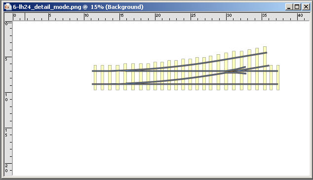
Martin Sorry if my explanations lacked clarity. The plotter/cutter I have just purchased is a KNK 'Zing' which has the capability of cutting 1/16" balsa, therefore I hope it can handle - with multiple passes - 1/32" basswood, suitable for point sleeper bases. The cutting software is 'Make-the-Cut', designed for the device (but capable of driving other cutter/plotters). It can import SVG, PDF and raster images for pixel tracing. TemPlot doesn't support SVG. Direct import of a TemPlot PDF doesn't give a 'cuttable' image. So I need a raster image that MTC can trace. [with a quite excellent trace capability] I go to the export menu item, and save the point template (with only rails, timber outlines and timber infill selected) as a PNG. File saves in TemPlot 'Images' folder. Go to Paint Shop Pro (Version 10) and open image for manipulating. And get the result shown in the attached screenshot. Here you can see where the dimensions I quoted come from. [OK I exaggerated a little!] I have a program that translates a PDF file to a JPG so I do have a work around. However I would like to know why the direct output to a raster file loses the correct sizing. Donald |
||
| Attachment: attach_1289_1759_screenshot.jpg 169 | |||
|
posted: 2 Jan 2012 19:04 from: Martin Wynne
click the date to link to this post click member name to view archived images |
Donald MacLean wrote: Go to Paint Shop Pro (Version 10) and open image for manipulating. And get the result shown in the attached screenshot. Here you can see where the dimensions I quoted come from. [OK I exaggerated a little!]Hi Donald, There are no real-world sizes in a raster image. It consists simply of rows of dots. In this case 4000 dots in each row. The size of the dots and hence the length of the row (width of the image) depends entirely on the display display device which you use to view it. In an attempt to be helpful, most image editing software makes a guess about the real world sizes by assuming the dot sizes are the same as the current screen dpi setting in Windows. However, you can set your screen dpi to whatever you want, so the image sizes shown vary accordingly. In this case you have your screen set to 96dpi in Windows, so the the image is shown as 4000 dots divided by 96dpi = 41.67 inches wide. I have my screen set to 120dpi, so if I viewed the same image file in the same software it would show as 4000 divided by 120 = 33.33 inches wide. Or not. Graphics programs tend to vary in the way they handle this.  Generally it's wise to completely ignore such dimensions and work only in pixels (dots) in graphics editor programs. Generally it's wise to completely ignore such dimensions and work only in pixels (dots) in graphics editor programs.You need to tell your cutter driver the dpi size to use for this PNG image. You can work that out by making a note of the width of the boundary rectangle in inches and dividing it into 4000. You can set the size of the boundary rectangle by selecting the boundary rectangle option on the export a file... dialog and then clicking the set... button. You can enter inch dimensions by prefixing them with a letter i. For example to create a boundary rectangle 10" x 8" located at the grid origin, enter 0,0,i10,i8 dimensions. Then export your image, and the dpi setting to use in the cutter is 4000 dots divided by 10 inches = 400dpi. If your cutter driver doesn't allow you to set the dpi figure, you will have to assume that it is using the printer resolution (probably 600dpi or maybe 300dpi) or the screen resolution (probably 96dpi) and do some trial and error on the image size. For example, if your boundary rectangle is 10 inches wide and you want to create an image at 300dpi, you should change the 4000 to 3000 dots (300dpi x 10"). If you want to create an image at 96dpi, change the 4000 to 960 dots (96dpi x 10"). However in this latter case the image quality will be much poorer. All this will of course be explained in the help notes for the TDV image exports when I finally get them written. I'm sorry they are not done yet, but I have made the point several times that the TDV is unfinished. It may have been unwise to release it in its present state as it is causing users such as yourself more confusion than it is solving. regards, Martin. |
||
|
posted: 2 Jan 2012 19:32 from: Donald MacLean
click the date to link to this post click member name to view archived images |
Martin To your last paragraph first! Disagree that you shouldn't have released this early version. What you have done is b____y marvelous! And I apologise for diverting you from developing the help notes with my inane quibbles. As I said in my last post I have found a workaround from PDF > JPG > MTC. Easier than going through the kind of mathematical hoops you describe! Where my confusion arose was not recognising that the 100% option applied ONLY to PDF export and DIRECT printing. Once again, your generous help and courteous responses are much appreciated. Thank you. Sincerely Donald |
||
|
posted: 2 Jan 2012 20:49 from: Martin Wynne
click the date to link to this post click member name to view archived images |
Donald MacLean wrote:As I said in my last post I have found a workaround from PDF > JPG > MTC. Easier than going through the kind of mathematical hoops you describe!Hi Donald, I can't believe that going all round the Wrekin like that is easier than creating the required output directly from Templot.  I will add options to set the image dpi directly instead of the dot width, and to set the image boundary in dots (at that dpi) instead of in mm. regards, Martin. |
||

| Please read this important note about copyright: Unless stated otherwise, all the files submitted to this web site are copyright and the property of the respective contributor. You are welcome to use them for your own personal non-commercial purposes, and in your messages on this web site. If you want to publish any of this material elsewhere or use it commercially, you must first obtain the owner's permission to do so. |