Templot Club Archive 2007-2020
|
|||
| author | remove search highlighting | ||
|---|---|---|---|
|
posted: 28 Mar 2012 09:14 from: mike47j click the date to link to this post click member name to view archived images |
I'm drawing a layout in 0 gauge, based on Greenwich Park (about 1900). There is a run round line between the platforms which needs a three-throw turnout. I can follow the tandem turnout for the central frog, but I'm not sure what to do at the toe end. In the image gallery is a drawing of a Great Central three-throw which shows the centre blades are 3ft longer than the outer blades. Due to the lack of space the other end of the crossovers will probably need to be 9ft curved 1:6, do I just start with a 12ft curved 1:6 for the three-throw ? And do I have to do anything special at the heel end ? Thanks Mike Johnson |
||
|
posted: 28 Mar 2012 16:35 from: Alan Turner
click the date to link to this post click member name to view archived images |
To my knowledge Three Throw turnouts were not used in running lines. However the principle is that each pair of switch blades has a long and a short blade. The inner blade is the short blade. You will also need a knuckle in the running rail. Alan |
||
|
posted: 29 Mar 2012 10:07 from: Martin Wynne
click the date to link to this post click member name to view archived images |
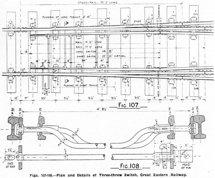
mike47j wrote: I can follow the tandem turnout for the central frog, but I'm not sure what to do at the toe end.Hi Mike, I think you mean this Great Eastern 3-throw? 2_280950_180000000.jpg  The full-size original scan is easier to read (click the links): http://85a.co.uk/forum/view_gallery_single.php?display=ALL&page=175 The inner switch rails extend 2ft-6in beyond the outer ones. To follow the drawing exactly will require a full custom design with partial templates, because each switch comprises one long inner switch blade (with undercut planing) and one short outer one (straight-cut joggled). The inner 14ft-6in switch rails have a real heel, the outer 17ft switch rails have a virtual heel at the same position (12ft). The rail width isn't specified, but the planing lengths suggest it is 3", giving 5" heel offsets for 2" clearance. An exact match is possible only in S7. For GOG-F and 0-MF the switches need to be longer with wider openings to create the wider flangeway clearance needed. It's all doable, but not very quickly! A reasonable approximation for a model would be to use two of Templot's standard 12ft switches, shortening the outer switch rail by blanking it back. A 1:36 custom switch would be a better match -- that's a 13ft-6in custom switch for 4.5" virtual heel as Templot's other straight switches. There are 2 drives (point levers). Each stretcher bar is attached to one long switch blade, and through a hole in the other long blade to the opposite short blade behind it. The drives have to be moved in sequence. Each one must be returned to normal before you can reverse the other. The drawing shows both drives normal, so either can move as drawn. One big problem with three-throw turnouts is that they often result in the V-crossings being opposite each other and therefore not properly checked for the middle road. regards, Martin. |
||
|
posted: 29 Mar 2012 13:40 from: mike47j click the date to link to this post click member name to view archived images |
OK. Perhaps it's quicker to only draw it roughly and then make it properly. In this photo http://www.disused-stations.org.uk/g/greenwich_park/index1.shtml It looks as if there might be extra check rails for the approach to middle road. Also the map labels that road as Engine Pit so it might not have been used very often. Thanks Mike Johnson |
||
|
posted: 29 Mar 2012 18:22 from: Jim Guthrie
click the date to link to this post click member name to view archived images |
Martin Wynne wrote: One big problem with three-throw turnouts is that they often result in the V-crossings being opposite each other and therefore not properly checked for the middle road.Martin, I am running into this problem with designing some tandem turnouts, where the crossing noses for the middle road were getting very close to being opposite each other. To check them properly, it would look as though putting them exactly opposite each other and using the wing rails as check rails would do the job. I can see that the wing rail will be a fair bit shorter on the switch side of the crossing than a normal check rail - is this the objection to having such a formation? Jim. |
||
|
posted: 29 Mar 2012 22:14 from: Alan Turner
click the date to link to this post click member name to view archived images |
mike47j wrote:
that's not a three throw it's a tandem turnout. Alan |
||
|
posted: 30 Mar 2012 00:21 from: mike47j click the date to link to this post click member name to view archived images |
Alan Turner wrote
Why do you say that ? Looking at the map and the photos it looks to me, to be too symetrical to be a tandem. And the extra check rails before the middle road appear to be on both sides. Of course I could be seeing what I expect to see and not what's actually in there. There is a tandem at the station entrance end, in the running line, which is the entrance to the bay platform, the departure platform and the run round loop. Mike Johnson |
||
|
posted: 31 Mar 2012 13:35 from: Martin Wynne
click the date to link to this post click member name to view archived images |
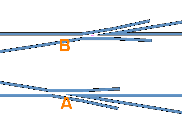
Jim Guthrie wrote:To check them properly, it would look as though putting them exactly opposite each other and using the wing rails as check rails would do the job. I can see that the wing rail will be a fair bit shorter on the switch side of the crossing than a normal check rail - is this the objection to having such a formation?Hi Jim, If the crossings are exactly opposite each other, the short section of wing rail between the knuckle and nose will act as a check rail for the opposite crossing, for slow-moving vehicles. So this formation is acceptable in yards and sidings, but not on a running line (not long enough and no proper check flare). The bigger problem arises where the crossings are not quite opposite, like this: 2_310829_130000000.png  Then wheels on the centre road cannot be prevented from hitting the nose at A because it is impossible to fit a check rail at B. regards, Martin. |
||
|
posted: 31 Mar 2012 17:01 from: Jim Guthrie
click the date to link to this post click member name to view archived images |
Martin Wynne wrote: The bigger problem arises where the crossings are not quite opposite, like this:Martin, If a check rail is fitted on the switch side of the knuckle at "B", would that not provide checking on the basis that the check rail operates on the total length of flange of a wheel in contact with it, so would still be applying a check to the trailing edge of the flange while the leading edge of the other wheel was encountering the crossing nose at "A"? Jim. |
||
| Last edited on 31 Mar 2012 17:03 by Jim Guthrie |
|||
|
posted: 31 Mar 2012 17:33 from: Martin Wynne
click the date to link to this post click member name to view archived images |
Jim Guthrie wrote:If a check rail is fitted on the switch side of the knuckle at "B", would that not provide checking on the basis that the check rail operates on the total length of flange of a wheel in contact with it, so would still be applying a check to the trailing edge of the flange while the leading edge of the other wheel was encountering the crossing nose at "A"?Hi Jim, The flange on a coach or wagon wheel doesn't span very much length below the rail top. You have to allow a flangeway in front of such a check rail, and you can't have a straight end on it because wheels running in the trailing direction may hit it. So it needs a short length of flare. It may just about work on a model where a derailment doesn't risk anyone's safety, but on the prototype the proper thing to do is to move the crossing to a position where it can be properly checked. Also if you do it on a model, some clever-clogs will come along and say "I think you'll find..." . regards, Martin. |
||
|
posted: 3 Apr 2012 00:01 from: Tony W
click the date to link to this post click member name to view archived images |
mike47j wrote: Alan Turner wroteHi Mike. It certainly looks like a Three Throw to me. The discussion about the crossing positioning is very relevent. Under the Section 'Design of Layouts' in the British Railway Track book it states that to achieve adequate checking of the third crossing when it becomes close to its opposite number they should be placed exactly opposite one another and the geometry should be arranged to achieve this. With a symetrical turnout this means that both A chairs will be on the same timber. This situation applies to both Tandem and Three Throw turnouts. However the main objection to Three Throws is at the switch end of the Turnout as when the centre road set it is not possible to maintain the track gauge at the tips of the second set of switch blades. This is why they were largely superceeded by Tandems. Tony. |
||
| Please read this important note about copyright: Unless stated otherwise, all the files submitted to this web site are copyright and the property of the respective contributor. You are welcome to use them for your own personal non-commercial purposes, and in your messages on this web site. If you want to publish any of this material elsewhere or use it commercially, you must first obtain the owner's permission to do so. |