Templot Club Archive 2007-2020
|
|||
| author | remove search highlighting | ||
|---|---|---|---|
|
posted: 31 Aug 2012 18:05 from: Compstructor
click the date to link to this post click member name to view archived images |
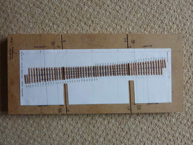
2376_311249_510000000.jpg Hi, I have spent the last week or so using Templot to design a set of Double slips in 2FS gauge, I was looking around for some info on hinging the crossing rails and to my total disbelief I read that a 1:10 double slip is a no-no and I should be using a switched diamond. Is this really true? Hi, I have spent the last week or so using Templot to design a set of Double slips in 2FS gauge, I was looking around for some info on hinging the crossing rails and to my total disbelief I read that a 1:10 double slip is a no-no and I should be using a switched diamond. Is this really true?I am also a bit confused over moving and non-moving K Crossings. Can somebody put me on the right track, pardon the pun. Shall I need to pull the sleepers up and start again? Photo attached .undefined Thank you in advance Kev. |
||
|
posted: 31 Aug 2012 18:58 from: Tony W
click the date to link to this post click member name to view archived images |
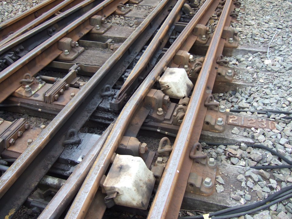
Hi Kev. No, from your picture you are doing your 1 in 10 double slip correctly. The rules for prototype diamonds is that for obtuse or K crossings, fixed crossings can only be used where the angle is less than 1 in 8. For those of 1 in 8 and upwards i.e. flatter, a switched crossing must be used. The situation is not quite as straight forward as this however as when the diamond is on a curve the angle where the change over occurs can be reduced further. The reason for this is due to the problem of checking the wheel flanges across the gap at the obtuse crossing as the the angle becomes more acute and the gap between the check rail and point rail increases. In model terms, wider than scale flangeways can also have an effect and reduce the maximum safe angle that should be used. The continuous running rail with a switched diamond solves this problem. What you cannot do is use the switches to change the route through the diamond, the switch blade pairs are always switched opposite ways. Separate slip roads are still required for this. I have added a picture of a 1 in 10 curved single slip I made some time ago in P4. You can see from this that all the switch blades are fixed at the heel end and flex when moved rather than hinged. Hope this answers your query. Tony. 2151_311356_090000000.jpg  |
||
| Last edited on 31 Aug 2012 19:02 by Tony W |
|||
|
posted: 31 Aug 2012 19:27 from: Compstructor
click the date to link to this post click member name to view archived images |
Hi Tony, I must admit, I do find it a bit confusing being a newb, but if you would confirm that: Your crossing (photo) switches from either side of the central sleeper rather than from each entrance road. If this is correct then I think I can figure it out on my work board. Many thanks Kev. |
||
|
posted: 31 Aug 2012 19:54 from: Martin Wynne
click the date to link to this post click member name to view archived images |
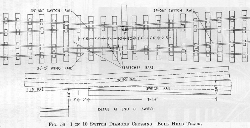
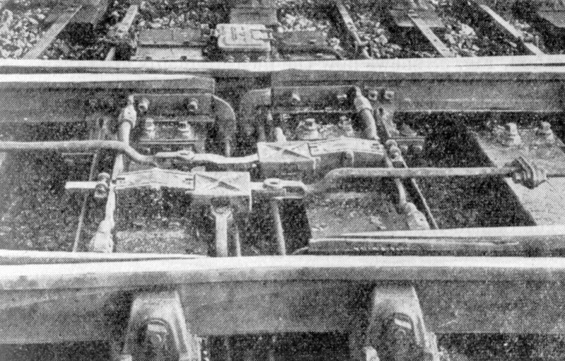
Hi Kev, Welcome to Templot Club. Here are a couple of images to help explain.These are switch-diamond-crossings (i.e. they have movable K-crossings), but you can add slip roads to make them into slips, just as for fixed K-crossing diamonds. The two sets of moving switch blades at the centre always move together, in opposite directions: switch_diamond_10bh.jpg  switch_diamond.jpg  Notice that in a flat-bottom switch-diamond (lower photo) the switch tips (points) are carried on two separate timbers. In a bullhead switch-diamond (upper drawing) both switch tips share a common wider centre timber. Here is an excellent picture from Mick Nicholson showing a flat-bottom double-slip with movable K-crossings. As one switch blade opens, the other closes. You can see that this doesn't affect the provision of the slip roads in the other rails: fb_movablek_dslip.jpg  © thanks to Mick Nicholson Using movable K-crossings will give you very much more reliable running at 1:10 angle, and they are much easier to construct because you don't have to find room for the K-crossing check rails. The only downside is the need for two extra point motors (or only one if you make a suitable rocking crank device to drive both K-crossing switches from a single motor). For more information about all this, click: topic about switch-diamonds . Ask again if you need more. regards, Martin. |
||
|
posted: 31 Aug 2012 21:18 from: Compstructor
click the date to link to this post click member name to view archived images |
Thanks Martin that looks straight forwards, I'll ponder them over the week end. Regards Kev |
||
|
posted: 31 Aug 2012 21:26 from: Tony W
click the date to link to this post click member name to view archived images |
Hi Kev. I expect Martin's reply has resolved any lingering confusion, but to confirm. The switch pairs either side of the central timber are switched to oppose to each other and set for the straight though routes only. They are quite independent of the entrance switches for the slip roads. Tony. |
||
|
posted: 31 Aug 2012 21:29 from: Compstructor
click the date to link to this post click member name to view archived images |
Thanks Tony for your added info, I shall play with it on Templot over the weekend and see if I can modify my plan. If not I will be back for more assistance. Have good weekend everyone. Kind regards Kev |
||
|
posted: 1 Sep 2012 00:16 from: Tony W
click the date to link to this post click member name to view archived images |
Compstructor wrote: Thanks Tony for your added info, I shall play with it on Templot over the weekend and see if I can modify my plan. If not I will be back for more assistance.Hi Kev. As I said at the start, it all looks correct to me. In default mode,Templot automatically changes the K crossing from fixed to switched when the crossing angle reaches 1 in 8 as it has done for your printout. You have already gapped your timbers and I wouldn't alter anything. Study the pictures and all should become clear. Construction is your next step. Tony. |
||
|
posted: 1 Sep 2012 00:57 from: Martin Wynne
click the date to link to this post click member name to view archived images |
Hi Kev, John Donnelly has just posted an excellent pic of Newcastle Central on the Scalefour web site: http://www.scalefour.org/forum/viewtopic.php?f=5&t=2191 At centre left is a curved single slip with movable K-crossings. Note the open switches at the centre and the lack of check rails there. At bottom left of the picture is part of a more conventional slip with fixed K-crossings (with check rails). regards, Martin. |
||
|
posted: 1 Sep 2012 12:56 from: Martin Wynne
click the date to link to this post click member name to view archived images |
And also in this topic on RMweb -- more slips and diamonds with movable K-crossings at the bottom of this photo: http://www.rmweb.co.uk/community/index.php?/topic/60308-newastle-central-station-bit-of-a-long-shot/#entry761669 Martin. |
||
| Please read this important note about copyright: Unless stated otherwise, all the files submitted to this web site are copyright and the property of the respective contributor. You are welcome to use them for your own personal non-commercial purposes, and in your messages on this web site. If you want to publish any of this material elsewhere or use it commercially, you must first obtain the owner's permission to do so. |