Templot Club Archive 2007-2020
|
|||
| author | remove search highlighting | ||
|---|---|---|---|
|
posted: 12 May 2013 19:14 from: Franz
click the date to link to this post click member name to view archived images |
Hello: I previously used TEMPLOT to create a couple of templates and then tape them down to built the track. However, time has passed and I have forgotten all then I learned of TEMPLOT. I have 2 drawings. One is a template of a standard turnout. This is a continental 750mm gauge track with a 1:7 Frog. The other drawing is a single line drawing of the station which appears to be to in the proper perspective horizontal and vertical when I drop onto Google Earth. I believe I need to approach this systematically. 1) Create a new Custom Gauge, 2) Create a standard template for turnout and track geometry and timbering, 2) Record this new template as a library, 3) Import the station track plan background into a new box, 4) Create full track template , print and build. In order to become more proficient with TEMPLOT, I need to learn the nomenclature, because it took me some time to move the peg to the frog point (FP) in order align the geometry as best as possible. Where is there a place to learn the acronyms? I am still working on item 1 and 2. I imported the Turnout template to the background, then rescaled the image by measuring off off a known dimension. I started modifying the gauge and a GWR old style hinged template which was close to the dimensions. I pegged the template over the frog point and it fell in close alignment. I still need to alter the hinge dimensions and the length of the point. However, I closed the file and when I reopened the file, I lost the background image. I eventually found the background, but is there a way to lock this with the storage box? Later, I would like to make a library template which holds all the design details of a 750mm track in HOe. How do I store the information in a file for reuse by future template? Is there a method of hiding the Timbers? These make it difficult to align the track. Paul |
||
|
posted: 12 May 2013 20:29 from: Martin Wynne
click the date to link to this post click member name to view archived images |
Franz wrote:In order to become more proficient with TEMPLOT, I need to learn the nomenclature, because it took me some time to move the peg to the frog point (FP) in order align the geometry as best as possible. Where is there a place to learn the acronyms?Hi Paul, Which version of Templot are you using? If not Templot2 please upgrade so that we can help you: message 10771 Here first are some of the basics: startup_pad.png  pad_symbols.png There is a list of the common acronyms at: http://www.templot.com/martweb/gs_geometry.htm#peg_positions Is there a method of hiding the Timbers? These make it difficult to align the track.Click the real > timbering > no timbering menu item. regards, Martin. |
||
|
posted: 12 May 2013 22:22 from: Franz
click the date to link to this post click member name to view archived images |
Martin, I am up to date with TEMPLOT2. It works quite well. I was not certain that eliminating the Timber would be reversible. It does help. I now need to determine what the colour code are for the hash marks on the rail near the switch. This is an area I need to work next. The Following items are requested for the switch entry. How are these measured from the prototype drawings? -------------------------------- lead length to heel (incl. planing) = 144.0 ( 42.04 model mm ) offset at the heel (heel spread) = 4.5 ( 1.31 model mm ) length of switch-front (stock-rail joint to toe) = 65.0 ( 18.98 model mm ) length of switch-rail (blade) = 174.0 ( 50.8 model mm ) length of stock-rail from joint = 360.0 ( 105.1 model mm ) ------------------- The only item I understand is Offset. But is the measured from the centerline or rail head vertical surface? |
||
| Last edited on 14 May 2013 05:44 by Franz |
|||
|
posted: 14 May 2013 09:01 from: Martin Wynne
click the date to link to this post click member name to view archived images |
Franz wrote:The Following items are requested for the switch entry. How are these measured from the prototype drawings?Hi Paul, Here is a diagram. The length of switch-front is marked a. The length of planing is marked b. The others are as shown. The heel offset is measured from the gauge-face of the stock rail to the gauge-face of the switch rail. Often the heel is coincident with the end of the switch rail, but not always. 2_231113_100000000.png  There is a lot more about all this in this topic: topic 2075 I now need to determine what the colour code are for the hash marks on the rail near the switch. This is an area I need to work next.You have lost me there.  Please can you clarify what you mean by the "colour code for the hash marks"? Showing where? regards, Martin. |
||
|
posted: 15 May 2013 11:06 from: Franz
click the date to link to this post click member name to view archived images |
Martin, Your image helps clarify most of my questions. THe colour confusion is regarding the yellow and blue hash marks as shown in the image above. Ther are other marks near the fine point. How do I dimension the joint from the fine point? Paul |
||
|
posted: 15 May 2013 11:19 from: Martin Wynne
click the date to link to this post click member name to view archived images |
Franz wrote: The colour confusion is regarding the yellow and blue hash marks as shown in the image above. There are other marks near the fine point.Hi Paul, I think we are losing something in translation on the word "hash". The blue marks across the rails show the position of rail joints. The cream marks between the rails are radial end marks. They show where one curve radius or straight ends and another curve radius or straight begins. The colours used for the above marks are not significant, you can set them in the trackpad and output menus to whatever you want. To dimension the V-crossing rail ends from the fine point, click the real > V-crossing options > customize V-crossing > menu items. regards, Martin. |
||
|
posted: 15 May 2013 11:43 from: Franz
click the date to link to this post click member name to view archived images |
Martin, That does clarify the colours. My difficulty is duplicating my reference design is dimensioned to 9.5 meter from the Fine Point of the V-Crossing to the Datum "Joint" (term used above). I can not get the dimensions less that about 10.5 meter without altering the V-Crossing to less than the 1:7. 1:7 is correct for all the other dimensions. I can not find a solution which allows me to reduce the Joint-FP length Perhaps I need to leave this long and adjust all the other dimensions to compensate for the longer entrance, but I expect there is a better solution. Paul |
||
|
posted: 15 May 2013 11:52 from: Martin Wynne
click the date to link to this post click member name to view archived images |
Franz wrote: My difficulty is duplicating my reference design is dimensioned to 9.5 meter from the Fine Point of the V-Crossing to the Datum "Joint" (term used above). I can not get the dimensions less that about 10.5 meter without altering the V-Crossing to less than the 1:7. 1:7 is correct for all the other dimensions. I can not find a solution which allows me to reduce the Joint-FP length.Hi Paul, Which joint do you mean? It would help if you could post your prototype drawing.  Try action > mouse actions:control/real > adjust V-crossing entry straight (or SHIFT+F11) mouse action to shorten the lead length. I'm going to rename this topic shortly because the reference to an image is misleading. regards, Martin. |
||
|
posted: 15 May 2013 19:09 from: Franz
click the date to link to this post click member name to view archived images |
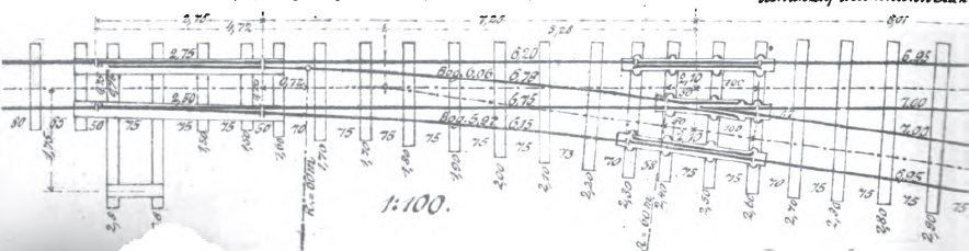
Martin Wynne wrote: Which joint do you mean? The Joint I refer is the item on the left of your image over the red dot. 2_231113_100000000.png The drawing is located on the bottom of the page at: http://www.laenderbahn-forum.de/zeichnungen/oberbau/josch/S-Spur2-Z.jpg |
||
|
posted: 15 May 2013 20:50 from: Martin Wynne
click the date to link to this post click member name to view archived images |
Hi Paul, Thanks for the drawing link. I have had a quick dabble and got quite close: trackpad view: 2_151537_280000000.png  sketchboard view in detail mode: 2_151537_290000001.png  I set the track gauge to 8.61mm with 0.60mm flangeways. I have no idea if this is correct for 1/87 H0e -- we have tried to get definitive information about this model gauge before. It seems that a UK-style 9ft straight switch is very close, so I used that as-is with some blanking on the switch front. It's not possible to read the dimensions clearly enough to do a proper custom switch. It needed only a slight adjustment to the V-crossing entry straight to match the 9500mm line, which I think is to the blunt nose, not the FP. I shortened the check rails by eye to the drawing. regards, Martin. |
||
| Last edited on 18 May 2013 13:38 by Martin Wynne |
|||
|
posted: 16 May 2013 10:34 from: Martin Wynne
click the date to link to this post click member name to view archived images |
Hi Paul, I have had a fresh look at this. The 5277mm dimension is clear enough and I think confirms that the crossing angle is 1:7 RAM and that the 9500mm dimension is to the FP as you said and not the blunt nose as I previously thought. I will work up a proper design for this turnout and post updated files later. regards, Martin. |
||
|
posted: 16 May 2013 11:48 from: Franz
click the date to link to this post click member name to view archived images |
Martin, Thank you for your efforts. I was getting very close to the overlay that you provided. You will notice at the left side the round circle indicates the turnout length. This can be extended - but not reduced in TEMPLOT. I was trying to reduce the length to the location which you have now aligned with the Origin (X = 0). You will notice that the stretcher is located on between the 2 long timbers. The toe end at the center of the strecher. I expect these details are altered after the length and other geometries are corrected. Paul |
||
|
posted: 16 May 2013 12:52 from: Martin Wynne
click the date to link to this post click member name to view archived images |
Franz wrote:You will notice at the left side the round circle indicates the turnout length. This can be extended - but not reduced in TEMPLOT.Hi Paul, The round circle is called the fixing peg. It can be reduced -- almost everything can be changed in Templot. To do what you want you can either: 1. blank off the unwanted length -- CTRL+F3 mouse action, or 2. create a custom switch with a shorter dimension for the switch front. You may be interested in this topic and video: topic 376 Sorry, it is years out of date and needs updating for the new features in Templot2. See also this topic: topic 2034 I will post a revised version of your turnout shortly. regards, Martin. |
||
|
posted: 17 May 2013 05:30 from: Martin Wynne
click the date to link to this post click member name to view archived images |
With 1:21 custom straight switch: 2_170327_140000000.png  2_170026_450000001.png  2_170026_460000002.png  2_170558_450000000.png  2_170558_460000001.png  2_170558_540000003.png  2_170558_490000002.png  Martin. |
||
|
posted: 18 May 2013 13:26 from: Martin Wynne
click the date to link to this post click member name to view archived images |
Hi Paul, I've spent quite a lot of time on this, trying to make sense of an illegible drawing. The best match I can achieve is in the attached file. I set the scale to 1:87 exact rather than 3.5mm/ft as this seems to be the norm for European models. The difference is very slight. It makes the model track gauge 8.62mm. I believe H0e is usually 9.0mm track gauge, but obviously you can't match a prototype drawing unless you have an exact scale track gauge. I set the flangeways to 0.60mm. We have tried to find the definitive dimensions for H0e in the past without success. In the UK the equivalent is called 009 using 9.0mm gauge with 0.85mm flangeways at 4mm/ft scale. I have done the design in metric full-size dimensions as on the drawing. Templot normally uses inches for full-size dimensions, hence the odd sizes displayed in the dialogs. You can enter mm dimensions by prefixing with a letter m. i.e. entering m254 inches is the same as entering 10 inches. I set the rail-head width to 45mm and the foot-width to 90mm, with rails vertical. This is entirely a guess, but the drawing appears to show a mark at the end of planing to confirm it. The best straight switch I can fit is at 1:21 deflection angle, length 3465mm. The heel blocks appear to be on a timber centre, although this causes a discrepancy in the timber spacings. You may want to do some more timber shoving on this. All timbers are 200mm wide (another guess), plain sleepers are 1600mm long (from the drawing). The switch rails and V-crossings are on sole plates, so the usual UK alignments to the timber centres do not apply. I set the blunt nose to 15mm (another guess), with the overlap on the A timber negative at -200mm. I adjusted the crossing entry straight to get the required lead length, with a good match to the drawing. Here are the switch dimensions: -------------------------------- Dimensions are in FULL-SIZE prototype MM, with model conversions at 3.5 mm/ft. Unit angles are RAM. This switch is a STRAIGHT pattern switch: lead length to heel (incl. planing) = 3465.0 ( 39.83 model mm ) offset at the heel (heel spread) = 165.0 ( 1.9 model mm ) length of switch-front (stock-rail joint to toe) = 715.0 ( 8.22 model mm ) length of switch-rail (blade) = 3465.0 ( 39.83 model mm ) length of stock-rail from joint = 4425.0 ( 50.86 model mm ) deflection angle at blade tip = 1 : 21.0 planing length (along stock-rail) = 946.06 ( 10.87 model mm ) heel angle 1 : 21.0 FB switch-rail foot-width at blade tip (from stock-rail gauge-face) = 69.85 ( 0.8 model mm ) sideways depth of joggle = 9.53 ( 0.11 model mm ) joggle-length in front of blade tips = 152.4 ( 1.75 model mm ) ------------------- Timber spacings (to timber centres) : switch-front is timbered: spacing back from toe (blade tips) to first front timber (J1) = 375.0 ( 4.31 model mm ) spacing back to next front timber (J2) = 0 ( 0 model mm ) spacing back to next front timber (J3) = 0 ( 0 model mm ) spacing back to next front timber (J4) = 0 ( 0 model mm ) spacing back to next front timber (J5) = 0 ( 0 model mm ) spacing forward from toe (blade tips) to first timber (S1) = 320.0 ( 3.68 model mm ) spacing forward to next timber (S2) = 610.0 ( 7.01 model mm ) spacing forward to next timber (S3) = 610.0 ( 7.01 model mm ) spacing forward to next timber (S4) = 610.0 ( 7.01 model mm ) spacing forward to next timber (S5) = 610.0 ( 7.01 model mm ) spacing forward to next timber (S6) = 705.0 ( 8.1 model mm ) spacing forward to next timber (T1) = 500.0 ( 5.75 model mm ) -------------------------------- 2_180747_550000000.png  Files attached below. regards, Martin. |
||
| Attachment: attach_1602_2213_franz_h0e_8p62_7ram.box 320 | |||
|
posted: 18 May 2013 13:32 from: Martin Wynne
click the date to link to this post click member name to view archived images |
Here is the BGS file. If you downloaded the previous one, please delete it (I modified the scaling by a fraction). |
||
| Attachment: attach_1603_2213_franz_h0e_7ram.bgs 306 | |||
|
posted: 18 May 2013 13:33 from: Martin Wynne
click the date to link to this post click member name to view archived images |
Here is the .sk81 image file. This needs to go in the same folder as the .bgs file, usually C:\TEMPLOT_DEV\SHAPE-FILES\ |
||
| Attachment: attach_1604_2213_franz_h0e_7ram.sk81 391 | |||
|
posted: 20 May 2013 01:45 from: Franz
click the date to link to this post click member name to view archived images |
Martin, Your template is fantastic. Drops directly on the drawing. Horrible drawing that it is, it is the best I have found. I have looked for the HOe standards and all I can find are the MOROP norms (NEM) http://www.morop.eu/en/normes/ It appears that MOROP treats the Gauge and the Scale separately. Thus there are spec for 9mm gauge independent of the N scale. 9mm would be the gauge of the track. I can not find any Finescale specifications for HOe. The Norms which best describe the required dimensions are NEM110, NEM104 and NEM310. Your efforts are greatly superior to mine. Prior to your help, I was close to getting the template configured. I was looking for the process of shortening the turnout forward of the toe. I found this references in one of your later links. I needed to "Adjust the Blanking Length". In order to be compatible with RTR stock I need to convert the template to 9mm Gauge. Is there a process of altering the gauge without returning to the beginning and needed to redevelop all the dimensions again? Thanks Again: Paul |
||
|
posted: 20 May 2013 04:01 from: Martin Wynne
click the date to link to this post click member name to view archived images |
Franz wrote: In order to be compatible with RTR stock I need to convert the template to 9mm Gauge. Is there a process of altering the gauge without returning to the beginning and needed to redevelop all the dimensions again?Hi Paul, The scale and track gauge are fundamental dimensions and Templot doesn't really expect you to change them afterwards on a customized template -- the results may be a bit unpredictable and require a lot of re-work. If you do not use an exact scale track gauge it will never be possible to fully match a prototype drawing, you can only ever produce an approximation. You can change the gauge in two ways. Try these: Method A. A1. click on the template over the drawing and then delete to the control. A2. put the peg on CTRL-3 or geometry > peg positions > peg on DP menu item. A3. put the notch under the peg -- DIVIDE key or geometry > notch > put notch under peg menu item. A4. gauge > modify current settings > modify track gauge... menu item. Set the gauge to 9mm. A5. gauge > modify current settings > modify flangeway gap... menu item. Set the dimensions to the MOROP standards (0.85mm and 1.5mm ?). A6. peg the template back onto the notch -- MULTIPLY key or geometry > notch > shift onto notch menu item. A7. on the background shapes dialog -- general options > show trackpad grid in front of shapes tickbox. You may decide that is as far as you want to go. However you will notice that the template is now too long at the switch joint (left-hand end) and too short at the exit (right-hand end). To correct the switch joint you can either a) slide the whole template to the right (SHIFT+F9 mouse action) -- the easiest solution , or b) change the switch front dimension in the custom switch, or c) blank off the overlap, or d) adjust the turnout radius.If you choose (b) or (c) you will afterwards need to extend the overall length (F4 mouse action) back to the required exit end at the right. If you choose (a) or (d) this will happen automatically. The latter (d) will give the closest match to the drawing, so: A8. SHIFT+F11 mouse action to adjust the V-crossing entry straight until the switch joint is back on the datum line. In the process you will lose one of the turnout timbers. To get it back -- real > timbering > timbering data... menu item and reduce the fill timber spacing (maximum) dimension to say 29 inches. A9. finally real > shove timbers... menu item and over to you to tidy them up as you think best. A10. finally don't forget to store & background the new template, INSERT key. And then save a new file. Method B. B1. click on the template over the drawing and then group select (toggle). B2. gauge > other gauges... menu item. B3. click the set custom > a button (top left). B4. enter a name, e.g. "H0e-9". B5. click enter custom settings, and enter the dimensions requested. B6. click the convert group button (above the list). B7. click OK on the confirm dialog. B8. on the timber dialog, click the blue bar use this length. B9. click OK. B10. press the HOME key to hide the control template. B11. click on the template and then delete to the control. B12. go to step A9. The result of this method is the same as sliding the template to the right (SHIFT+F9) after A7. regards, Martin. |
||
|
posted: 28 Jan 2015 00:27 from: Franz
click the date to link to this post click member name to view archived images |
Hello, I have returned to designing the narrow gauge template after a sabbatical. I have updated the template to 9mm H0e NEM gauge and defined the sleepers and timbers per the prototype. I am however having trouble with the transition of the turnout timbers to road sleeper spacing at the exit of the turnout. This occurs on both the main road and turnout road transitions. The prototype tightened the spacing of the sleepers at the rail gap and the adjacent sleeper before following a wider gap for the remainder of the rail. The same gap is used at the entrance and exit of the turnout. I defined the Rail length and Sleeper spacing in the TEMPLOT file and this transition is correctly defined in the road and at the turnout entrance. I can not get the transition to be correct at the exit of the turnout. The Timbers are "Equilized Constant". The equilized timbers are X1-X9 and then th elong timbers start at S21, S22, S23, T1. I am having trouble getting the last Long equalized timber into the turnout automatically and I added a bonus timber , shoved, twisted and lengthened the timber. The remainder of the timbers are named using the convention of the Main Road sleepers (That is "E1, E2, E3,...) and are co located with the S21-T1 timbers. Is automatic exit road sleeper spacing possible or is timber shoving required for each turnout inserted into the track design? Paul |
||
| Last edited on 28 Jan 2015 01:23 by Franz |
|||
|
posted: 28 Jan 2015 00:49 from: Martin Wynne
click the date to link to this post click member name to view archived images |
Hi Paul, The number and spacing of crossing timbers under the vee rails and the spacing from the last crossing timber to the vee rail joint is set at real > V-crossing options > customize V-crossing > vee rail... menu item: 2_271937_110000000.png  The spacing from the joint to the first exit sleeper E1 is determined by your plain track settings at: real > plain track options > rail lengths and sleeper spacings... menu item. If you need to shove any timbers to get the desired result for a customized template, the shoved timbers will be retained provided you always copy the control template rather than mint a new one. You may also want to set tools > make tools: options > retain shoved timbers menu item. if you post a screenshot or a .box file I can answer in more specific detail. regards, Martin. |
||
|
posted: 28 Jan 2015 02:46 from: Franz
click the date to link to this post click member name to view archived images |
Martin Wynne wrote: Hi Paul,Martin, I found this reference http://templot.com/companion/index.html?timber_spacings_overview.htm which helped explain the wing rail front and vee rail settings. I now have a seventh equalized timber, but overlapped with a straight timber and a sleeper. I have attached the template and the box. Paul |
||
| Attachment: attach_2048_2213_sa_schmalspur_1b_2015_01_27_2124_25.box 211 | |||
| Last edited on 28 Jan 2015 03:37 by Franz |
|||
|
posted: 28 Jan 2015 03:38 from: Franz
click the date to link to this post click member name to view archived images |
Template File is attached |
||
| Attachment: attach_2049_2213_EW_1b_1zu7_template.jpg 588 | |||
|
posted: 1 Feb 2015 01:54 from: Martin Wynne
click the date to link to this post click member name to view archived images |
Hello Paul, Thanks for posting your files. You seem to have got in a bit of a muddle. Your drawing has only 8 timbers in the switch: 2_312047_340000000.png  But in your custom switch you have defined spacings for more than 20 switch timbers: spacing forward to next timber (S2) = 29.53 ( 8.62 model mm )You need to terminate the list of spacings by entering a zero (0) at the heel of the switch section. For the purposes of timbering that is normally where the equal spacings in the closure section begin. I will have a look at this for you. regards, Martin. |
||
|
posted: 1 Feb 2015 03:59 from: Franz
click the date to link to this post click member name to view archived images |
Martin, Thank you. I believe the switch starts at the rail joint just in front of the long timbers for the point rodding. This allows the mainline to start with the proper sequence. I was challenged at the exit and turning road. If you think there is an error in the turnout, I appreciate any help. I was a bit confused regarding the switch timbers and all the timbers associates with the entire turnout. The that the timbers in the prototype template are square on until timber 11. I defined the timbers up to the that value (and more). If I defined the timbers to the heel, then the timbers in the closure section are equilized. By defining these to a higher number, the timbers stay square until the wing rail front. You provided very helpful advice in a earlier response to provide better defintions. I have not corrected the mistake in my file. One other detail question: What is T1 and T2 timbers? The drawing does not include all the exit details. It is cut short. Paul |
||
| Last edited on 1 Feb 2015 17:40 by Franz |
|||
|
posted: 2 Feb 2015 16:31 from: Martin Wynne
click the date to link to this post click member name to view archived images |
Hi Paul, How does this look? I added the two first timbers as a dummy switch front, although the rail joint is shown immediately in front of the switch toe. 2_021114_460000001.png  2_021114_470000004.png  2_021114_470000003.png  2_021114_470000002.png  2_021114_460000000.png  This is the first time in years that I have set "equalized constant" timbering on a turnout. Then I restored timbers T2 - T6 to square-on by entering 0 degrees twist in the shove timbers. The others have been shoved into position and length adjusted as best I can read from the drawing. Other dimensions, rail section, blunt nose, etc. as in my previous message in this topic. The turnout can only be an approximation, because the scaled gauge is 8.62mm, whereas this is set to 9.0mm gauge. .box file attached. .bgs and .sk81 in following messages, with image scaled to fit. regards, Martin. |
||
| Attachment: attach_2057_2213_paul_german_turnout_mods.box 177 | |||
|
posted: 2 Feb 2015 16:35 from: Martin Wynne
click the date to link to this post click member name to view archived images |
The .bgs file. |
||
| Attachment: attach_2058_2213_paul_turnout.bgs 203 | |||
|
posted: 2 Feb 2015 16:36 from: Martin Wynne
click the date to link to this post click member name to view archived images |
The .sk81 image file. This needs to be saved in the same folder as the .bgs file. |
||
| Attachment: attach_2059_2213_paul_turnout.sk81 268 | |||
|
posted: 3 Feb 2015 11:46 from: Franz
click the date to link to this post click member name to view archived images |
Martin, That looks fantastic. I will download the files and review this during the week. Best Regards Paul |
||


| Please read this important note about copyright: Unless stated otherwise, all the files submitted to this web site are copyright and the property of the respective contributor. You are welcome to use them for your own personal non-commercial purposes, and in your messages on this web site. If you want to publish any of this material elsewhere or use it commercially, you must first obtain the owner's permission to do so. |