Templot Club Archive 2007-2020
|
|||
| author | remove search highlighting | ||
|---|---|---|---|
|
posted: 28 Jun 2013 12:08 from: TonyHagon
click the date to link to this post click member name to view archived images |
(This text and images awaiting review by Martin for accuracy and because I am sure that there is a better way of doing it than I describe here!) In developing the templates for Brighton 75A, I wanted to add the position of the conductor rail to the running tracks of the West Coast (Hove) branch and West Sidings. Here's how I did it: First of all, some sums... The extremely helpful webpage: http://homepage.ntlworld.com/russelliott/3rd-4th.html shows the distance from the inside face of the running rail to the centre of the conductor rail to be 1' 4" = 5.3mm in 4mm/ft (I ignored the tolerances given on the webpage). Using the rail section drawings lower down the same page for the 106lb rail, the rail head is given as 1.08 mm. Take half of this (0.54mm) and subtract from the dimension above to give the distance between the inside face of the running rail and the inside face of the conductor rail. In 4mm/ft this equates to 4.76mm. Double this and add it to the normal track gauge (I use P4 so I add 9.52 to 18.83 to give 28.35mm). Half of this (14.175mm) is the distance from the track centre to the face of the conductor rail. Plain track 1. Click a plain track background template to which you wish to add a third rail. I'll use template 298 for this..... 1876_280534_150000000.png 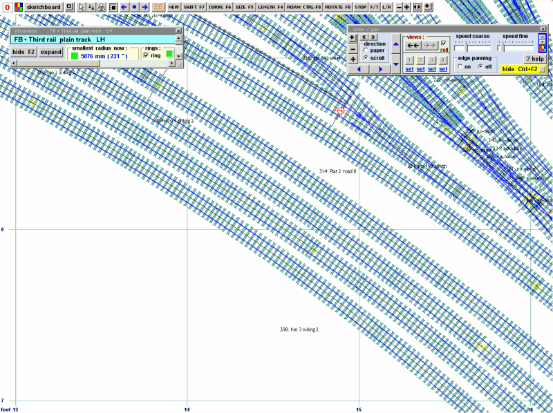 2. Click main-copy to the control 3. Click template-mint from currentnull 4. Click gauge - modify current settings - modify track gauge Your current track gauge is shown as 'modified track gauge between rails' and we need to change this to the distance between two conductor rails outboard of the running rails, in my example above = 28.35mm. Click OK 1876_280607_400000000.png 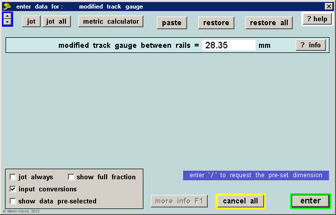 1876_280609_200000000.png 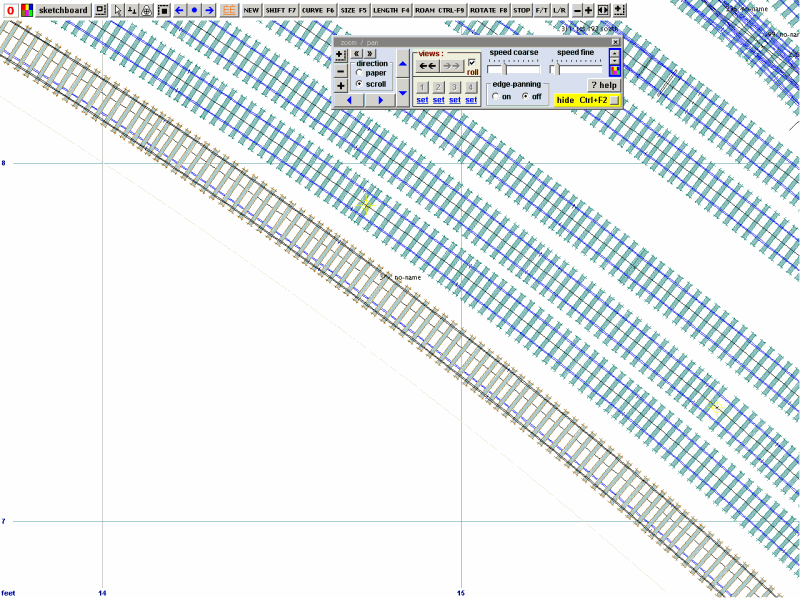 null 6. You can use Ctrl+F6 to slide the template through the peg until it is in your required location. You can lengthen it using F4 but don't extend it beyond the peg or the curving (if present) will be wrong. 7. Click 'real - timbering - no timbering'. You now have two rails, so select which side the conductor rail should be. 1876_280619_080000000.png 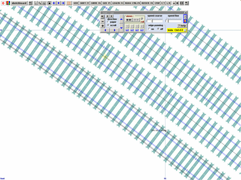 8. Click Do-omit rails and joint marks - choose either TS or MS - I chose TS. 1876_280625_500000000.png 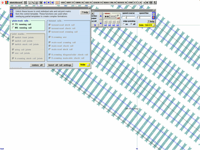 null Remember that conductor rails swap sides of the track to avoid wear on the pickup shoes or turnouts and sometimes are missing altogether over e.g. level crossings and metal underbridges or where two electrical sections meet and are then connected by cable. Where the conductor rail swaps from one side to the other, there is a length of overlap, the Russ Elliott page gives this as 12 timber bays for Southern Electric. To achieve this overlap: 10. Select a length of plain track where the overlap is to occur and create the pair of conductor rails from that template as above - or - take an existing length of conductor rail where it will be swapped over and delete it to the control. 11. Click real- timbering - no timbers but do not omit either rail as before. Click Main- save and background. 12. Do the same for the adjacent length where the swapping will take place. You should now have two adjacent templates both with the two conductor rails showing. 13. Return to the first template now on the background and Main-delete to the control. You may find you have to extract this from the Main -Storage box rather than trying to click the conductor rail template on the trackpad. 14. With the peg at the opposite end of the template (Ctrl-0 or Ctrl-1) to where the overlap is to take place, click F4 and extend the template by 6 timbers. Click Do - omit rails or joints and delete one of the rails (TS or MS). Click Main-Store and background. 15. Repeat 12-13 for the adjacent template but extending the conductor rail opposite to the one you have extended above. 1876_280649_440000000.png 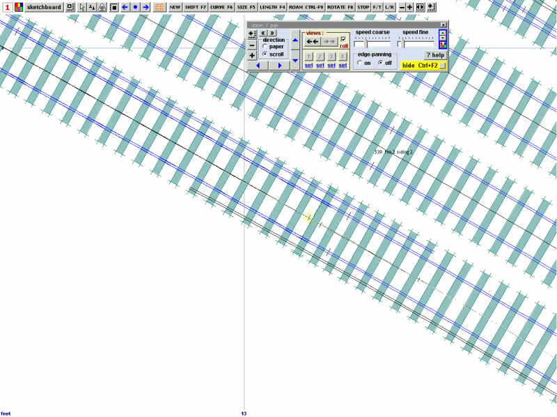 (I wondered who would be the first to spot that, Wilson... what's he talking about? Count the number of overlap timbers) To add a conductor rail to a turnout: 16. Click the respective turnout. 17. Click Main - Delete to the Control 18. Click geometry - peg positions - peg on TP 19. Click geometry - notch - put notch under peg 20. Click Main - Store and background 21. Click a different template and Main -Delete to the Control, then click Main - Store and background 22. Click the turnout again and Delete to the control 23. Click gauge - modify current settings - modify track gauge 24.Change the modified track gauge between rails to (in my example above) 28.35mm. Click Enter and OK You will notice that the turnout control template is offset as it is aligned on the main or turnout stock rail. 25. Click on the background template underneath, then click Main- Peg Align Tools - align the control template over and snake on to peg - facing to facing. 1876_280544_560000000.png 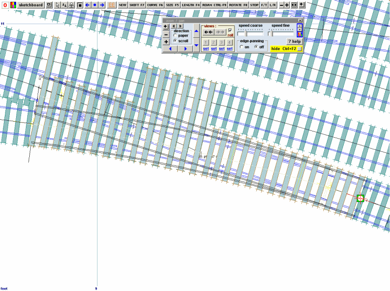 The turnout is not aligned on the track centres and the crossing has disappeared off the end, the lead between switch and crossing has extended but this is not a problem as we are only interested in one or other (or usually both!) stock rails. Use F9, Ctrl+F3 and (judiciously) F4 to adjust the template so that the track centres align with the background template. (Be careful about the use of F4 to lengthen the turnout rails. Use F9 and Ctl-F3 first of all.) It will take a bit of manouevring to ensure that the track centre marks overlap, but I personally wasn't too worried about absolute accuracy as these additional conductor rails are on the templates only as a guide to where they would be started and terminated. 1876_280549_370000000.png 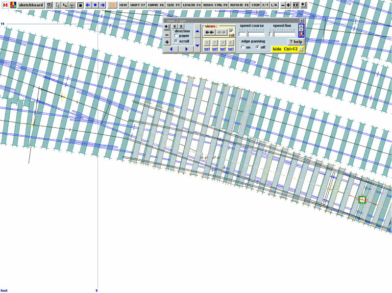 26. Click real - timbering - no timbering 27. Click do - omit rails and joint marks 28. Delete everything except the stock rail you wish to retain as the conductor rail. If you look closely at the image above, you can see an overlap with the turnout to the right of the template. F3 (approach road) applied to each template in turn cures that. Note that I have used F4 to shorten the template so that the uppermost rail will form a V with the plain track above it. I will bring this back a few more timbers using F4 to clear the other conductor rail ramp. 29. Click Main - store and background null 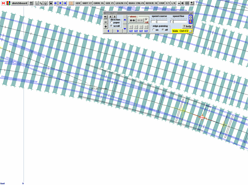 That's better! The conductor rails are now where I want them. There is a portion where the two turnouts meet where both sides have a conductor rail, but reference to photos will determine if this is correct. This is actually a trap point from the sidings, so the lowermost conductor rail is ok to terminate where it does (see image below). null 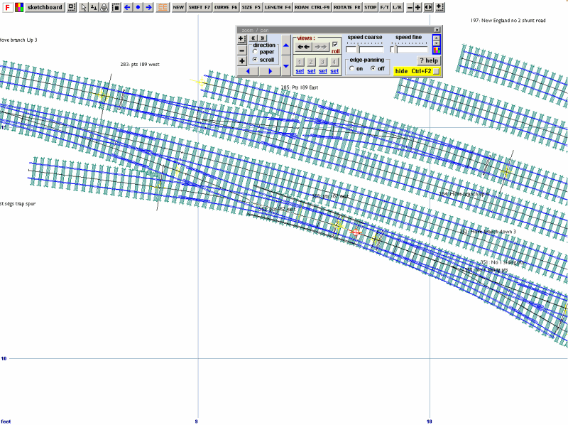 With these extra rails on the respective templates, reference to photos will help to position them accurately when the time comes to construct them, which at this rate of progress will be around 2078! I haven't bothered to change the railhead settings and these are all shown as bullhead which is obviously wrong. As I said before, this is purely to get an idea where to start and stop the various conductor rails, rather than a scale drawing of them. Now.. to work out how to fix working collector shoes to my Bachmann 4CEP.... (with the return current going back through the running rails, obviously!) Best regards Tony Hagon |
||
|
posted: 28 Jun 2013 23:33 from: Martin Wynne
click the date to link to this post click member name to view archived images |
Hi Tony, Many thanks for doing all that. For plain track may I suggest an alternative approach? You can create a conductor rail on each side by modifying the platforms (real > platforms... menu item). I believe conductor rails are not usually installed adjacent to a platform, so using a platform as a conductor rail won't restrict using it for its intended purpose where needed. Set the width of the "platform" to match the conductor rail top 3.1/4" (3.25"). Set the front edge spacing to the required dimension 14.3/8" (14.375"). 2_281800_000000001.png 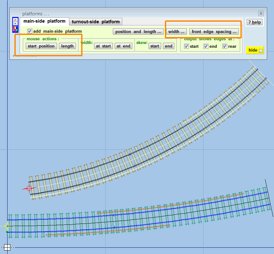 You can then add "platform" conductor rails where required, and adjust the start position and length by mouse action to create the desired overlaps. Here is an output view: 2_281800_000000000.png 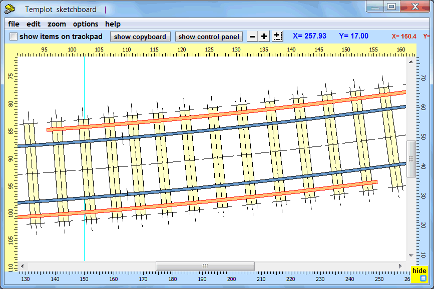 The great advantage of this method is that it is a single template, and can therefore be curved, copied, re-used, stored as a library template, etc., with the conductor rails included. This method won't work as it stands for turnouts, where you will still need partial templates, although you could overlay them as these plain track centre-line templates. See tools > make split > make plain track turnout road > on internal geometrical radius menu item. • This method can't show the rail foot for the flat-bottom conductor rails, so if you need the foot shown on the templates, your method of using wide gauge track will have to be used. Or you could set the conductor rail width to match the rail foot instead of the rail head, and adjust the front spacing accordingly. regards, Martin. |
||
|
posted: 29 Jun 2013 00:20 from: TonyHagon
click the date to link to this post click member name to view archived images |
See? I TOLD you that Martin would have a better idea! . Ironically, Brighton DID have a conductor rail up against platform 2, and for many years both up and down main platforms at Gatwick Airport had them along the whole length of the platforms because the 6 foot contained the point rodding. 1876_281919_360000000.jpg 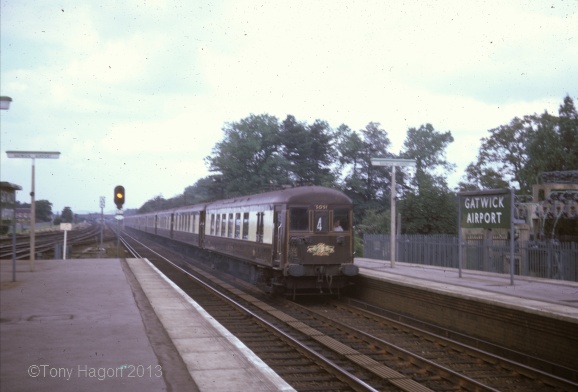 Off now to try Martin's method... TH |
||
|
posted: 3 Aug 2013 07:51 from: Fleischmann66
click the date to link to this post click member name to view archived images |
I have just come back from a visit to the UK and was intrigued by the possibility of adding a third rail to my layout, so thanks for this post; it is very useful. Whilst not a templot question, can anyone advise the best way to raise the third rail up to the required height? I suppose in HO/OO one could use code 100 rather than code 83 rail but I am wondering if this is the usual practice or whether spacers are normally used? regards Andrew |
||
|
posted: 3 Aug 2013 08:17 from: Martin Wynne
click the date to link to this post click member name to view archived images |
Hi Andrew, A range of 4mm conductor-rail supports/insulators and fittings is available from C&L: http://www.finescale.org.uk/index.php?route=product/category&path=346_347_360 A very detailed page of notes and pictures of electrified track has been prepared by Russ Elliott at: http://homepage.ntlworld.com/russelliott/3rd-4th.html regards, Martin. |
||
| Please read this important note about copyright: Unless stated otherwise, all the files submitted to this web site are copyright and the property of the respective contributor. You are welcome to use them for your own personal non-commercial purposes, and in your messages on this web site. If you want to publish any of this material elsewhere or use it commercially, you must first obtain the owner's permission to do so. |