Templot Club Archive 2007-2020
|
|||
| author | remove search highlighting | ||
|---|---|---|---|
|
posted: 25 Jul 2014 08:53 from: Michael Woolford
click the date to link to this post click member name to view archived images |
I have been working on the final stages of my design which mostly includes shoving the timbers. A while ago, Martin pointed out to me that there was one area that had less than the minimum track spacing, of which I have been trying to rectify. This particular issue is not much of a problem as it is because of a crossover (this can be relocated). Upon further investigation it seems that there are several other areas that also need attention. I am now very concerned that a large amount of the design will need to be redone which could take me a considerable amount of time. What I'm looking for is if someone could be kind enough to look over my design and check to see where I have issues. I have a rough idea of where the problem areas are, but for some reason I have the thought that even the adjacent track centres could be off. I really need a second opinion on this and seriously hope that only minimal changes will need to be made. I have attached the unaltered box file and will attach the box file with the removed crossover in a second post. Thanks in advance Michael |
||
| Attachment: attach_1890_2493_Station_Layout_23Jul14.box 304 | |||
| Last edited on 25 Jul 2014 08:57 by Michael Woolford |
|||
|
posted: 25 Jul 2014 08:55 from: Michael Woolford
click the date to link to this post click member name to view archived images |
Box file with removed crossover attached. | ||
| Attachment: attach_1891_2493_Station_Layout_24Jul14_A02.box 294 | |||
|
posted: 25 Jul 2014 16:28 from: Martin Wynne
click the date to link to this post click member name to view archived images |
Hi Michael, A trick you can use to check for tight spots quickly is to switch on the track background on the sketchboard, and set the width of the background slightly less than the required track centres. For example, the minimum spacing for 6ft way is 11ft-2in centres, or 134 inches (44.67mm). So if you set a track background at 131 inches wide, there should be a 3 inch gap between track backgrounds, or a 1mm gap in 4mm/ft scale. Setting a bright page colour (e.g. red) makes this gap easily visible. Zoom and pan all over the track plan to see it: 2_251100_390000001.png  I added some dummy tracks at 44.67mm centres, for comparison with your track plan. You can see that there is no 1mm red gap at A which probably needs fixing, and a reduced gap in places at B which may be acceptable, although not strictly prototypical. You should always try to use the make double-track and make crossover tool functions, so that the required spacing is created automatically. This isn't always possible of course. If you tick the box to show the above on the trackpad, you can make adjustments. Set the trackpad colour to red for the same effect: 2_251100_390000000.png  Swap to and from the sketchboard to update the view. The sketchboard items are added to the trackpad as a bitmap, so rounding effects may affect the precision when zooming. The track background settings are at output > output drawing options > menu items. You need to turn on the track background on the trackplan tab on the sketchboard control panel. The above is just to find tight spots quickly. For accurate work the spacing-ring tool should be used. The spacing-ring can be attached to the dummy vehicle tool as a means to run it along it each track. The spacing usually needs to be increased on sharp curves. This can be checked for running clearances using the dummy vehicle tool. tools > spacing-ring • dummy vehicle menu item. regards, Martin. |
||
|
posted: 26 Jul 2014 14:01 from: Martin Wynne
click the date to link to this post click member name to view archived images |
Hi Michael, Here is the dummy vehicle tool being used on that tight spot. I made a dummy vehicle copy on the outer track, and here the dummy vehicle is being rolled along the turnout road on the inner turnout: 2_260808_320000001.png  At A above I have attached the spacing-ring to the dummy vehicle. You can see that it is infringing the opposite rail, indicating that the track spacing is too close. Rolling the dummy vehicle with the spacing-ring attached is a convenient way to check the spacings. But to work against the adjacent rail like this, the ring inner diameter needs to be set according to your track gauge. For 6ft way 44.67mm centres, the settings are: P4 68.67 mm EM 69.3 mm 00-BF 16.5 71.0 mm 00-SF 16.2 71.3 mm If you find the calculation troubling, you can set up some tacks at the required spacing, zoom in and adjust the ring size visually by mouse action. 2_260808_320000000.png  At B you can see that the 6" clearance envelope on the vehicle is conflicting, but the actual body sides are clear with about 6" (2mm) between them. That is a bit tight, allowing for different vehicle dimensions (the above is using the default settings), body sway, wheelset/gauge freedom, offset bogies or axles, and other variables in a model. Prototypically it is too close, but you may decide that it is acceptable to avoid reworking the track plan. You could try printing out the templates and carefully standing your longest vehicles on them to check the running clearance. tools > spacing-ring • dummy vehicle menu item: 2_260857_540000000.png  regards, Martin. |
||
|
posted: 26 Aug 2014 00:05 from: Tony W
click the date to link to this post click member name to view archived images |
Hi Michael. I have been having a quick look at your track plan and yes, there are a few issues with the track spacing in places. Hopefully Martin has already pointed you in the right direction. Your biggest problem is with the two inside curves at the bottom of the track plan, but there are others. I have checked the track centre spacing of your templates and these are set to the default for straight track of 44.67mm. I will have another look at tomorrow and get back to you. Not sure just how big a job correcting things will be until I have done so. Regards Tony W. |
||
|
posted: 27 Aug 2014 23:38 from: Tony W
click the date to link to this post click member name to view archived images |
Hi Michael. Having now had a more detailed look at your track plan, I feel that although it may be possible to improve the design as it stands, I think it could be look rather better than it does as there are also several alignment issues that could be improved on. This is not to detract from what you have achieved so far which is quite impressive in parts, but if you are happy for me to do so, I would like to see what I can do with it. I will get back to you and hopefully save you some work. Tony W. |
||
|
posted: 28 Aug 2014 08:57 from: Michael Woolford
click the date to link to this post click member name to view archived images |
Thanks Tony, that's very kind of you, I look forward to seeing what you come up with. Michael |
||
|
posted: 2 Sep 2014 21:24 from: Tony W
click the date to link to this post click member name to view archived images |
Hi Michael. I have finally got there. I have left most of the ends of the tracks where you had them. I have had to widen the track centres of the three sidings at the top of your plan in order to achieve sufficient clearance. The trick is to plan out the plain track layout first and get the clearances right before inserting turnouts into them. I would also advice using the longest turnouts you sensibly can and have used some C switches to improve the radii of the diverging track on the inside of the curve. B-6s are all well and good in their place, but not on the inside of a curve. The Double slips are now all straight as you will stand a better chance of building them than the curved ones you had previously. I have sorted out the outside slip for you but have left most of the timber shoving for you to have a go at. By all means let me have another look at the plan when you have done so and will give it the once over as Timbering is rather more of an art than a science. I hope you like what I have done with it. Regards Tony W. |
||
| Attachment: attach_1940_2493_station_approach_version_2.box 319 | |||
|
posted: 2 Sep 2014 22:04 from: Michael Woolford
click the date to link to this post click member name to view archived images |
Tony, I'm sat here saying to myself how beautiful that is! The curves flow so effortlessly and make it so pleasing to look at. That must have been a lot of work to re-design so much of the geometry. There is one thing that I would question which is whether it is prototypically correct for C10 sized turnouts in such a low speed area? Although I suppose they are justified by easing the curvature and improving the overall geometry? I’m not asking you to change anything but it’s one of the first things that came to mind when I looked through everything. I can’t thank you enough for taking the time to do this. Many thanks, Michael |
||
| Last edited on 2 Sep 2014 22:08 by Michael Woolford |
|||
|
posted: 2 Sep 2014 22:24 from: Tony W
click the date to link to this post click member name to view archived images |
Hello Michael. The prototype invariably used turnouts much longer than the average modeller does. There was a crossover on a 6 chain curve into an industrial complex at the station that I hope one day to model. I measured the lead of these and was surprised to find they were D-9s, so I don't think you need to worry too much on that score. C and D are the shortest switches would be used on a main line and B switches would be reserved for goods yards and loco sheds. Regards Tony W. |
||
|
posted: 2 Sep 2014 22:27 from: Michael Woolford
click the date to link to this post click member name to view archived images |
Tony, Thanks for clearing that up, I will probably change the crossovers on the straight section then. Not too much work, just means I'll have to do the timber shoving again. Thanks again, Michael |
||
|
posted: 2 Sep 2014 22:46 from: Tony W
click the date to link to this post click member name to view archived images |
Michael. As you have the space it seems a shame not to, but I thought I would let you make that decision. The improvement in appearance when your trains run through them will be worth it. It has been a fair bit of work but some things are just a challenge knowing the potential of those sweeping parallel curves. I am glad you like the result. Regards Tony. |
||
|
posted: 3 Sep 2014 13:22 from: Tony W
click the date to link to this post click member name to view archived images |
Hi Michael. I have been having another think about your carriage sidings as I was not totally happy with the current arrangement. I think it would be much more prototypical if both sidings combined to form a single entry to the main line and combine the trap points in the one road. This does give some benefit with the lengths available too. I have saved the box file as a separate group. Have a look at it and see what you think. To add this to the existing design, first remove the existing background templates to the left of the curved turnout into the top carriage siding. One way of doing this is to select them as a group, so you can see clearly which templates you have chosen, then open the storage box and select the Group drop down menu. Choose the Wipe group from background option. This does not delete them but makes them unused. To add the new templates use the add file button in the Storage box and select the Carriage siding group file. The new sidings will be added in their correct place. Regards Tony. |
||
| Attachment: attach_1941_2493_Carriage_sidings_group.box 320 | |||
|
posted: 6 Sep 2014 11:33 from: Michael Woolford
click the date to link to this post click member name to view archived images |
Tony, Having just had a look at the changes, I started to think about why you had not trapped the two roads leading into the main road; then I looked closer and realised that you had included the trap in the turnout. For some reason, it is not something I have seen modeled very often and it is nice to be able to include. It certainly makes the arrangement look tidier. Thanks again, Michael |
||
|
posted: 11 Oct 2014 14:56 from: Michael Woolford
click the date to link to this post click member name to view archived images |
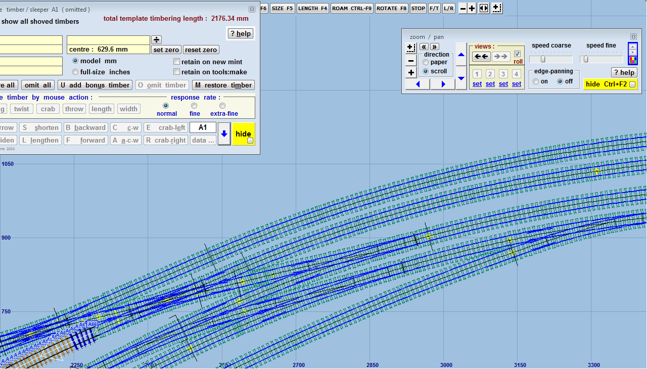
I'm currently spending a bit of time shoving the timbers and have just realised that my 10ft spacings are the wrong way round. The two central tracks on the approach lines are the mains with the outer two acting as head-shunts/carriage sidings. Somehow I get the feeling that this may be a bit trickier than I'm hoping. It seems all that is needed is to alter the crossovers in the station throat and a little tweaking of the geometry. |
||
| Attachment: attach_1972_2493_trackpad_screenshot_2014_10_11_1448_52.png 323 | |||
|
posted: 11 Oct 2014 19:38 from: Martin Wynne
click the date to link to this post click member name to view archived images |
Hi Michael, Can you clarify the exact purpose of the outer tracks? It wasn't clear to me when we looked at your plans that they were sidings.  If they are merely head-shunts or access loops to a yard or carriage sidings I think you may be able to get away with what you have there, with the 10ft way between the running lines. However, if they are sidings on which rolling stock will be left parked I think you do need to have them 10ft way from the running lines so that there is safe access on both sides. You can probably find locations which don't obey this rule but it doesn't really look right. regards, Martin. |
||
|
posted: 11 Oct 2014 20:00 from: Michael Woolford
click the date to link to this post click member name to view archived images |
Hi Martin, They are not ordinary sidings. They will be used as head-shunts and sometimes as a carriage siding if there is no empty platform or middle-road free. It is only likely that when they are used as carriage sidings, they will be occupied by full length trains for a relatively short period of time while the coaches are serviced, before the next journey. Michael |
||
|
posted: 11 Oct 2014 20:21 from: Martin Wynne
click the date to link to this post click member name to view archived images |
Hi Michael, In that case I think you may be able to get away with leaving them as they are. But it won't look quite right to have rolling stock parked on them with trains on the running lines passing so close while there is a 10ft way between the running lines. You need to put something in the 10ft way to justify the arrangement. For example an underline girder bridge with the tops of the girders visible alongside the tracks. Or an overbridge with two spans and a central pier. Bridges often cause the track spacings to depart from the strict rules. regards, Martin. |
||
|
posted: 11 Oct 2014 22:51 from: Michael Woolford
click the date to link to this post click member name to view archived images |
To save changing things too much, I might include something to justify the spacing by the crossovers, then ease it out towards normal spacings. Michael |
||
|
posted: 12 Oct 2014 22:05 from: Tony W
click the date to link to this post click member name to view archived images |
Hi Michael. Whilst the track spacings could be altered, you should bear in mind that a wider formation will result with 10 + 6 + 10 ft spacings than 6 + 10 + 6 ft as you have them now, meaning there could be other implications as the bottom road will have to be moved further south. If this is not a problem then the question you have to answer is whether you can live with the "wrong" spacing or not. It will be much easier to alter the Templot plan at this stage than build the layout and wish you had done it differently. I also notice that your control template (plain track) has several shoved timbers that are not at right angles to the rails. It would be quite unusual to have more than one on the exit roads from a turnout as this would unduly weaken the ability to maintain the track gauge. Regards Tony W. |
||

| Please read this important note about copyright: Unless stated otherwise, all the files submitted to this web site are copyright and the property of the respective contributor. You are welcome to use them for your own personal non-commercial purposes, and in your messages on this web site. If you want to publish any of this material elsewhere or use it commercially, you must first obtain the owner's permission to do so. |