Templot Club Archive 2007-2020
|
|||
| author | remove search highlighting | ||
|---|---|---|---|
|
posted: 2 Jan 2015 10:43 from: Phil O
click the date to link to this post click member name to view archived images |
I have just been perusing Mr Smiths book on Switch and Crossing practice and I have noticed that on his 1 in 6 common crossing the check rails span 4 timbers (page 33, fig 13). Where as the timbering diagram for a 1 in 8 turnout the check rails span 5 timbers (page 36, fig 14). Does anyone know at what crossing angle the change takes place between 4 timber checks and 5 timber checks. Cheers Phil |
||
|
posted: 2 Jan 2015 11:04 from: Martin Wynne
click the date to link to this post click member name to view archived images |
Hi Phil, 7.3/4 See diagram and column L on page 141 Martin. |
||
|
posted: 2 Jan 2015 11:19 from: Martin Wynne
click the date to link to this post click member name to view archived images |
p.s. Phil, See also: http://www.scalefour.org/resources/GWRtracknotes/R2999.pdf "LENGTH OF GUARDS:" at top left of page. |
||
|
posted: 3 Jan 2015 14:17 from: Phil O
click the date to link to this post click member name to view archived images |
Thanks Martin The link to the Scale four page is very useful. Thanks Phil |
||
|
posted: 2 Feb 2015 14:45 from: Phil O
click the date to link to this post click member name to view archived images |
Hi Martin I am now trying to set up customised turnouts and have hit a small snag when in the wing and check rail menu. There is CHECK-RAIL WORKING LENGTH and CHECK_RAIL EXTENSION LENGTH How do I input the info for 11ft 6 ins and 14ft Guards, Please. Guard length info from your Scalefour Society link above Cheers Phil Cheers |
||
|
posted: 2 Feb 2015 15:34 from: Martin Wynne
click the date to link to this post click member name to view archived images |
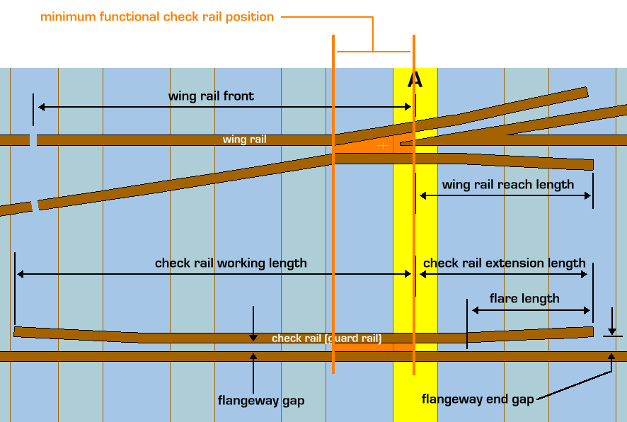
Hi Phil, Templot dimensions the check rails from the centre of the A timber, so you need to calculate the relevant dimensions from the GWR drawings. Here's a diagram: 2_251630_520000000.gif  regards, Martin. |
||
|
posted: 3 Feb 2015 09:09 from: Phil O
click the date to link to this post click member name to view archived images |
Thanks Martin I will have a look at that later. Cheers Phil |
||
|
posted: 8 Feb 2015 13:51 from: Phil O
click the date to link to this post click member name to view archived images |
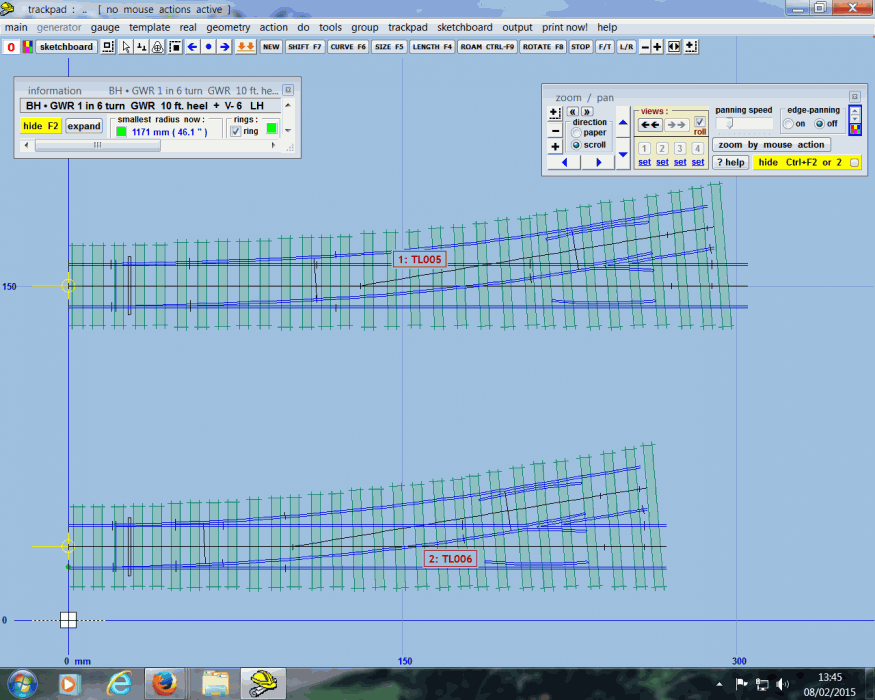
Hi I have finally had a go at a GW custom turnout, which has worked out pretty well except that I can't find a way of getting the "V" and wing rail joints in the correct places, this is only a cosmetic issue as I know they fall midway between the closed up timbering. 38_080849_160000000.png  Cheers Phil |
||
| Attachment: attach_2064_2607_1_in_6_GW_turnout_EM_gauge.box 223 | |||
|
posted: 8 Feb 2015 22:52 from: Martin Wynne
click the date to link to this post click member name to view archived images |
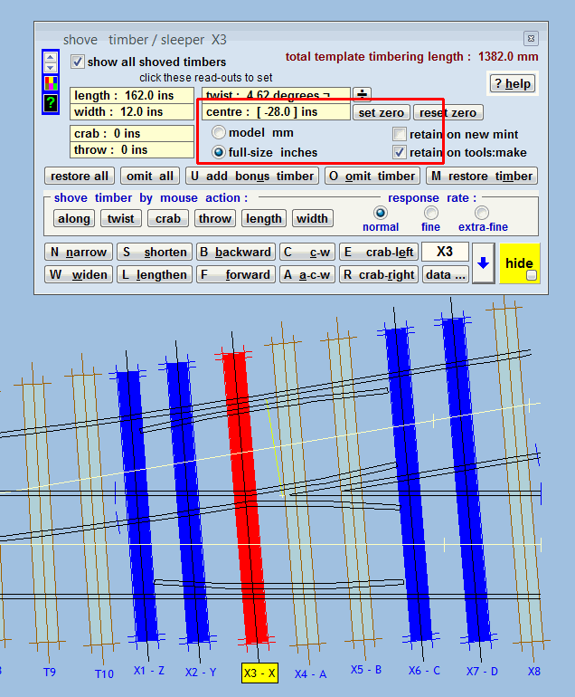
Hi Phil, The first thing to change if you want to match a prototype GWR turnout is change to a generic type V-crossing. This will increase the lead length, but it will still be under scale because you are using EM instead of exact-scale track gauge. There is no way round that. You may also want to change to CLM angles, but since there is no way to get an exact scale lead length in EM, there is not much practical reason to do that. For the wing rail front, the first thing is to establish the dimension from the rail joint to the centre of timber "A". From the drawing (page 141 in the GWSG book) that is 97.5 + 3 = 100.5 inches. Subtract from that the spacing from the rail-joint to the adjacent timbers, 12.5 inches. Leaving 88 inches spanning 3 timbers, so the average spacing is 88 / 3 = 29.33 inches. This is the spacing to enter for the wing rail front, plus the 25 inch timber spacing (2 x 12.5 inches) at the joint, and Templot will put the joint in the right place, and the timbers next to it. You are then left to shove the other two timbers to the required spacings, which back from timber "A" are 28 inches and 32 inches. 2_081731_560000000.png  Set the full-size inches option. Select timber "A" and set zero button. Select timber "X", click the centre readout and enter -28 inches (negative because backwards from "A"). set zero on that timber. Select timber "Y", click the centre readout and enter -32 inches (negative because backwards from "X"). You can adjust timber "Z" similarly if you wish (there is no dimension on the drawing). • N.B. Make sure you tick the box for retain on tools:make so that these timber shove settings are not lost when doing tools > make crossover, etc. .box file attached. I restored the T timbers to no shoving, so you may want adjust timber lengths, etc. The vee rail settings work the same way, I haven't made any changes to those. regards, Martin. |
||
| Attachment: attach_2065_2607_phil_gwr6.box 229 | |||
|
posted: 9 Feb 2015 11:09 from: Phil O
click the date to link to this post click member name to view archived images |
Hi Martin Many thanks, the bit I had not got my head around was that I needed to average the spaces for all the timbers, thanks for the heads up on the crossing type, I had always assumed it was a regular crossing. I'm still learning things about this amazing programme, even though I have been using it for years. Cheers Phil |
||
| Please read this important note about copyright: Unless stated otherwise, all the files submitted to this web site are copyright and the property of the respective contributor. You are welcome to use them for your own personal non-commercial purposes, and in your messages on this web site. If you want to publish any of this material elsewhere or use it commercially, you must first obtain the owner's permission to do so. |