Templot Club Archive 2007-2020
|
|||
| author | remove search highlighting | ||
|---|---|---|---|
|
posted: 5 Apr 2015 09:59 from: keithj15
click the date to link to this post click member name to view archived images |
Fellow club members have started an O gauge Broad Gauge project, and asked me to draw up their track plan. Having gathered together all the track stats from the Broad Gauge Society, and created a custom gauge, all looked good until I tried to create a regular crossover. I then found the turnouts overlap and the all important V's don't generate on the template. I have tried all the variations of the turnout geometry, but have concluded that there must be some simple parameter that I have missed — possibly in the custom template dialogues, and this screws up the correct creation of the regular crossing — and maybe other configurations of turnout and crossing templates yet to be encountered. Can anyone help point out what I am missing? I have attached a box file showing the problem. regards Keith Johnson |
||
| Attachment: attach_2102_2669_7mm_Broad_Gauge.box 234 | |||
|
posted: 5 Apr 2015 10:14 from: Alan Turner
click the date to link to this post click member name to view archived images |
Widen the track centres using Geometry/Adjacent Track Centres. regards Alan |
||
|
posted: 5 Apr 2015 10:40 from: keithj15
click the date to link to this post click member name to view archived images |
Hi Alan, This was my first thought too, being that it was easy, and during the setting up of the custom settings Templot "suggested" adjacent widths in excess of 113mm. Unfortunately this is one of those compromises that are not acceptable by the modellers as they are trying to stay true to the original plans, which have a 6ft way, as St Ives was the last broad gauge station to be completed, but still with a view to the "big change-over" which was immanent. I am sure there is a setting in the custom turnout or linked to the turnout geometry — but I have just been unable to locate it. regards Keith |
||
|
posted: 5 Apr 2015 11:03 from: John Shelley
click the date to link to this post click member name to view archived images |
keithj15 wrote: Hi Alan,You aren't getting confused between "Track centres" and "Gap between tracks" are you? "Track centres" = "Gap between tracks" + "Track Gauge". For Broad Gauge this would be 6ft +7ft = 13ft. (ignoring that 1/4 inch) Cheers for now, John from 33820 St Ciers sur Gironde |
||
|
posted: 5 Apr 2015 11:16 from: Martin Wynne
click the date to link to this post click member name to view archived images |
Hi Keith, Are broad gauge double tracks really that close? You have them set at 13ft-0.3/8in = 91.2mm centres. This is less than double the track gauge (14ft) which means that the V-crossings overlap and it is impossible to fit proper check rails for them.  Unfortunately the make crossover functions in Templot can't work properly in such a circumstance. There are two ways you could proceed -- correct the templates afterwards, or not make straight crossovers that way. But firstly you need to set up proper broad gauge turnouts -- you have them set for REA switches which were not introduced until about 1925 and never used by the GWR. I think you could probably use the GWR loose-heel 12ft switches in the switch list if you don't have the dimensions to set up a full custom switch. First restore the geometry > turnout road exit length > normal setting. Next it is important to increase the crossing entry straight so that the turnout curve does not extend past the crossover mid-point. Use the SHIFT+F11 mouse action to do that with the peg on CTRL-5: 2_050551_010000000.png  Now, for a straight crossover: 1. CTRL+F12 and reduce the exit track to the minimum. 2. either store it on the background and then geometry > shift/rotate > rotate 180 degrees. or tools > make mirror on peg, then template > swap hand: 2_050606_130000000.png  On reflection it would have been better to extend the crossing entry straight even more, back to the wing rail joint. Do you have any prototype drawings for this? I seem to remember it was all in an early issue of Model Railway Journal. I will go and find it. You still have the tasks of adjusting the check rail ends to clear the conflicts and shoving the timbers (presumably to represent baulk road). Having done all that it would be worth storing it as a library template for future re-use. For a curved crossover, a different method is needed, so I will reply with that again shortly. regards, Martin. |
||
|
posted: 5 Apr 2015 11:30 from: Martin Wynne
click the date to link to this post click member name to view archived images |
p.s. Keith, For 6ft way you need to add in two rail widths (say 2.1/2in for bridge rail?) 6ft + 7ft-0.1/4in + 2 x 2.1/2in = 13ft-5.1/4in = 94.06mm centres in 7mm/ft scale. Martin. |
||
|
posted: 5 Apr 2015 11:43 from: keithj15
click the date to link to this post click member name to view archived images |
I am bursting to try out your suggestions — but senior management have just arrived with a massive list of Easter Sunday Lunch demands, so if I want that On30 Climax next month I am forced to comply. The sacrifices we make for others... but we love them I have been granted remission for tomorrow, so that's good :-) |
||
|
posted: 6 Apr 2015 10:33 from: Martin Wynne
click the date to link to this post click member name to view archived images |
Hi Keith, The article in MRJ No.0 (the special preview issue) by Andrew Wiles shows the GWR broad gauge spacing as 6ft-6in to the gauge faces of the rail. (This dimension was still being used by BR(W) into modern times. This means that with the rail width at 2.3/4in the 6ft way between the rails on GWR lines is actually 6ft-0.1/2in, and the track centres 11ft-2.1/2in.) So for broad gauge the track centres are 13ft-6.1/4in = 94.646mm at 7mm/ft. regards, Martin. |
||
|
posted: 6 Apr 2015 12:38 from: keithj15
click the date to link to this post click member name to view archived images |
Hi Martin, Whooee, you have the complete MRJ collection from No. 0 !?! Thats a great resource. I shall apply the settings to the test piece I am working on in Templet. I have sent you a rather chunky email with photos and maps of St Ives circa 1890. It shows that the station crossover is on a curve, so I am hoping that with all the new settings this is going to be possible to do albeit with a fair bit of fiddling. Any more tips for this will be gratefully received. Best regards Keith  |
||
|
posted: 6 Apr 2015 16:34 from: Nigel Brown click the date to link to this post click member name to view archived images |
Hi Keith Any chance of loading some of this stuff here? I think some of us would be interested to know what the broad gauge track at St. Ives looked like. Also we might be able to help with further questions. Cheers Nigel |
||
|
posted: 6 Apr 2015 19:23 from: keithj15
click the date to link to this post click member name to view archived images |
Hi Nigel, Unfortunately much of the material I have is copyright, but as soon as I have approval for the Templot templates and track specs -- I can redraw the map/plan compessed and with all of the adaptions for false perspective. Meanwhile I shall make a note of the links I used on the web and post them here. Regards Keith |
||
|
posted: 6 Apr 2015 19:39 from: keithj15
click the date to link to this post click member name to view archived images |
Hi Martin, As there is no straight crossover in the plan, rather than spend time cleaning that up I chose to make a crossover on a curve and clean that up just to see what was involved. On first attempt I am reasonably pleased, my only reservations is the amount of timber interlocking within the crossing -- it makes it look a bit over-engineered, plus the general sleeper spacing (30") is looking a bit tight, making the timbers on and around the tie bar very crammed. I have attached the box file for perusal and comments. There is so little information, photographic or technical, on sleepered broad gauge turnouts I suspect whatever we do, if it looks right it is probably very near the prototype, coupled with the fact there are no living witnesses around to start an argument anyway. Regards Keith |
||
| Attachment: attach_2103_2669_7mm_Broad_Gauge_stage02.box 246 | |||
|
posted: 7 Apr 2015 11:29 from: Phil O
click the date to link to this post click member name to view archived images |
Hi Keith I think it looks tight because of the gauge,one gets used to looking at standard gauge turnouts. No doubt if you put a standard gauge turnout of the same size it wouldn't look so tight. I look forward to seeing the progress. Cheers Phil |
||
|
posted: 7 Apr 2015 11:59 from: keithj15
click the date to link to this post click member name to view archived images |
Hi Phil, When I print the template out and compare with my OO finescale of Daventry Station, and those for my On30 projects, it looks OK — but after gazing at the stuff on the screen for "hours" paranoia demands a second (or more) opinion. I suppose increasing the timber spacing would risk it looking oddly like narrow gauge... Time to STOP OVERTHINKING !!! regards Keith |
||
|
posted: 7 Apr 2015 12:49 from: keithj15
click the date to link to this post click member name to view archived images |
Nigel Brown wrote:Hi Keith Hi Nigel, Naturally, with half a dozen of us in the broad gauge project all scouring the internet for any information about St Ives Cornwall c1890 we gathered lots of stuff, sadly not all broad gauge nor railway related. However, I found a few of the links which should lead you on to many more. http://www.broadgauge.co.uk/locations/torquay_station.shtml http://en.wikipedia.org/wiki/Locomotives_of_the_Great_Western_Railway http://commons.wikimedia.org/wiki/File:St_Ives_station_view_c1890.jpg http://www.francisfrith.com/st-ives The last is very protective of copyright, and will pursue all infringements very aggressively — so you can share the link, but never the image. Hope this helps regards Keith |
||
|
posted: 7 Apr 2015 14:50 from: Nigel Brown click the date to link to this post click member name to view archived images |
Keith Thanks. Fascinating. I see that the platform was much shorter in broad gauge days. After conversion it appears the main platform was rebuilt so that the edge was further away from the station building, and extended, in the process allowing the goods siding to be also used as a bay. Good luck with the project. Should be a good one. Nigel |
||
|
posted: 7 Apr 2015 15:22 from: Matt M.
click the date to link to this post click member name to view archived images |
Hi Keith, I would assume you guys have the Great Western Railway Journal late summer 1992 Special Cornish Issue with its nice potted history of the line? If not, it may be of use to track down a copy. With the GWR being a very conservative company in regards to its PW development you would probably find the post gauge conversion track timbering to be very similar to the broad gauge version. Correct chairs and rail profile will probably be harder to sort. Francis Frith may be very aggressive in protecting its business but I doubt it would be through copyright on an image that dates from the 1880s or 1890s that were used for the postcard industry. That is why the images that they post on the website are of poor quality. If you purchase a high quality version you will effectively enter a contract which they would attempt to use against you. They are also careful not to claim copyright of images in their terms and conditions. But it always a good idea to be polite to those businesses that provide services that we can use. Keeping them going is of long term benefit to future researchers. Looking forward to the end result, it is such pretty line. Regards, Matt M. |
||
|
posted: 7 Apr 2015 15:50 from: keithj15
click the date to link to this post click member name to view archived images |
Hi Matt, I agree some of the images are quite poor due to age etc, but their maps and plans are often the only source of information, and these have been acquired from unsupervised clearouts of local government archives in the 70s and 80s "if we don't need it - bin it brigade" — and it is their maps that brings most litigation — the OS on the other hand are more laid back when it forms part of research. I will post my own version of St Ives when it is done. Two of the guys are planning to spend a fee days down there spending 30% at the local museum http://www.museumsincornwall.org.uk/St-Ives-Museum/Cornwall-Museums/ and 70% in the Sloop Inn http://www.sloop-inn.co.uk Its all about priorities — pouring over old manuscripts is thirsty work, apparently. As chief planner I may just have to join them  regards Keith |
||
|
posted: 8 Apr 2015 06:45 from: Matt M.
click the date to link to this post click member name to view archived images |
Hi Keith, If you post an item on the internet that is out of copyright you can't stop someone copying it. The images are poor deliberately to encourage purchase and protect their collection's commercial worth. And that is understandable. The digital age with internet has made it very easy to copy and disseminate material that both private and public entities have used to create profit and help fund the building and maintenance of collections. If they are from the original plates then they should be quite good in full reproduction. The fact that some seem to have quality problems associated with emulsion failure on glass plates suggests that, at least in some cases, they aren't just copying the postcards. (Lens of Sutton have a few of these early St Ives postcards too). If things are the same legally the same there as here in New South Wales, (and most of our government processes are similar for obvious reasons), then the Crown never relinquishes ownership, even if the object was thrown away at some stage. However the image is considered to be in public domain and control is a little hard to establish at that point. They can however ask for the original back. So if the maps and plans are ex-government and over a certain age there is no copyright as such. The same with drawings that are done by business and privately. So these private and public entities are using contract law to enforce a version of copyright according to ownership. It is dubious at best as ownership does not confer copyright. This is a problem that museums around the world are facing at this time. Due to the Great Western Railway Journal issue I mentioned, I have already access to an OS for 1877 so have an idea of what the group are trying to re-create. Also a copy of the OS for 1908. I note that there is a shot on page 10 of that GWRJ issue of the post broad gauge line that suggests that the leads for the platform, the bay and the goods shed are a little closer together than the 1908 OS would suggest, being a very interesting curved tandem. The 1877 OS suggests that the platform bay lead is closer to the loop lead on the viaduct at this time. A good photo of that would be a corker. Enjoy the fruits of the research... Matt M. |
||
|
posted: 8 Apr 2015 07:15 from: Martin Wynne
click the date to link to this post click member name to view archived images |
Hi Matt, OS Maps in the UK are out of copyright 50 years after publication. See: http://wiki.openstreetmap.org/wiki/Out-of-copyright_maps Which means we are currently up to 1964. There are many web sites taking advantage of this, see for example: http://www.sabre-roads.org.uk/maps/ http://wtp2.appspot.com/wheresthepath.htm http://maps.nls.uk/about.html That doesn't necessarily mean you can use someone else's scan file without their permission, you must make your own scan. regards, Martin. |
||
|
posted: 8 Apr 2015 09:35 from: keithj15
click the date to link to this post click member name to view archived images |
Hi Matt Thank you for your legal take on copyright. I am thinking that if I have spent some time cobbling together a useable map from internet screen grabs from a variety of sources, then it could be just a modern equivalent of objet trouvé (found art) created for no financial gain Hi Martin, and thank you for yor comments and links, I will take a look. Also did you ever get my emails, and have you had a chance to look at my attempt at the curved crossing? regards to you both Keith |
||
|
posted: 8 Apr 2015 09:56 from: Martin Wynne
click the date to link to this post click member name to view archived images |
Hi Keith, Yes, I received your emails. I will reply on here when I've had time to have a proper look at the design. regards, Martin. |
||
|
posted: 8 Apr 2015 13:15 from: keithj15
click the date to link to this post click member name to view archived images |
Hi Martin, I have attached my latest rendering of the crossover in front of the station building. I am concentrating on this template because Peter the project leader, has worked out that this item will allow him to calculate the final board(s) sizes and logical breaks where the boards join together. This file should drop neatly in front of the background shape of the map I emailed to you. BTW -- is it possible to attach more than one file at a time to these messages? regards Keith |
||
| Attachment: attach_2106_2669_7mm_Broad_Gauge_stage03.box 153 | |||
|
posted: 8 Apr 2015 15:02 from: Martin Wynne
click the date to link to this post click member name to view archived images |
Hi Keith, Surely that is far too short? Judging from the indicated points positions on the map (marked red below), the turnouts need to be something like GWR 12ft switch + 1:13 crossing angle (retaining your setting for the crossing entry straight): 2_080948_350000000.png  (When the gauge is non-standard, Templot's chosen combinations of switch and crossing angle in F5 are not applicable.) I'm still very puzzled by the close track centres, because it makes it almost impossible to fit working check rails. Do you have any photos of the middle of broad gauge crossovers? You can attach only one file per message on Templot Club. Just make a separate reply for each additional file. Add a brief note to each one because you can't attach a file to an empty message. May I gently draw your attention to paragraph 11 at: http://templot.com/companion/index.html?terms_of_use.htm I really don't want to feel that I am under an obligation to make a reply. That was the reason for making Templot2 free to use. regards, Martin. |
||
|
posted: 8 Apr 2015 15:32 from: Martin Wynne
click the date to link to this post click member name to view archived images |
Alternatively, something like an 18ft switch with 1:10 crossing angle is probably a better turnout design (but doesn't match the drawn crossover road on the map very well). As before this retains your setting for the crossing entry straight: 2_081029_000000000.png  regards, Martin. |
||
|
posted: 8 Apr 2015 17:28 from: keithj15
click the date to link to this post click member name to view archived images |
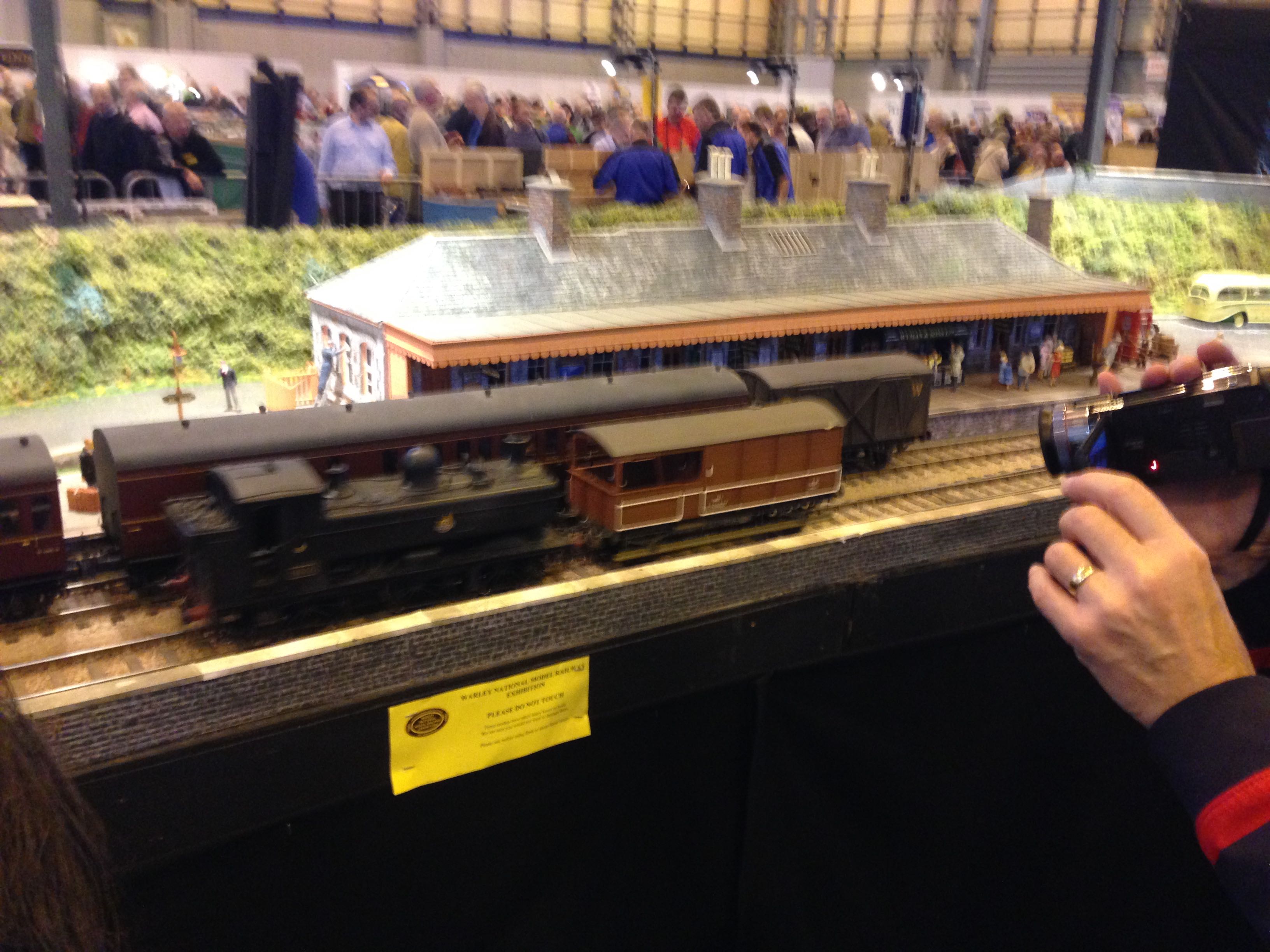
Hi Martin, Item 11 read and duly noted — beer ration has been revoked for 7 days  On my early attempts before I started the topic, I composed the map, and quickly created a complete rough working of the whole plan in Templet using GOG-F with GWR 14ft heel turnouts — all just to get an idea of size and scale. Having done this it all looked good until I output a PDF, added a 300mm sq grid and discovered that the crossover was massive, even bigger than the Gauge 3 version we saw at Warley. In fact when I look at the photos I took they didn't include the crossing at all(see attached) So it became a given that we would have to cheat or do the thing in N So I was instructed to do the crossover as a 1:6 or 1:7 to reduce the overall length — the test in GOG F proved it would reduce very nicely — but when i tried it in the broad gauge it all went 'orribly wrong and I started this topic. When you gave me those first suggestions I started to get things to work at last. The latest attempt (stage03) has a straight line length between tie bars of just over a meter, compared the plan distance of at least 1.6m. Sincere apologies for any confusion caused. Your latest templates really look the part, with the straight crossing whereas mine have the S curve. For modern traffic that would be a problem but in our period of 1890, excluding the locos they are all 4-wheelers with little difference between passenger and wagon. We will have to make some allowance for gauging on the platform, however photos of GWR at the time show the height of the platform is much lower anyway, with boxes placed below the doors to help the ladies alight more easily — a throwback to the stage coach. We have a project meeting tonight, so all will be discussed. Following this I will need to create a new map of St Ives to fit into the size of the baseboards, which will be in the form of an arc from the road bridge by the engine shed to the point at the end of the line. Given the interest shown thus far I shall keep posting our progress. Best regards Keith |
||
| Attachment: attach_2107_2669_IMG_0871.jpg 182 | |||


| Please read this important note about copyright: Unless stated otherwise, all the files submitted to this web site are copyright and the property of the respective contributor. You are welcome to use them for your own personal non-commercial purposes, and in your messages on this web site. If you want to publish any of this material elsewhere or use it commercially, you must first obtain the owner's permission to do so. |