Templot Club Archive 2007-2020
|
|||
| author | remove search highlighting | ||
|---|---|---|---|
|
posted: 31 May 2016 12:22 from: Gavin Rose click the date to link to this post click member name to view archived images |
Hello all. 'Knapford Junction' pre 1955 version. I have been designing and re-designing this plan for several years on and off and now which to finalise the plan so it can be built. Martin kindly asked me to post it so he could start me off on a few pointers with which I again extend much gratitude for the offer. I do want to learn to use Templot but like many I'm having difficult getting to grips with it. if there is no file or pic it is because I am trying to add them. I have added the pic to the layout plan, or at least 1 version of it but I haven't added the Anyrail file as it keeps giving me an error message. |
||
| Attachment: attach_2290_2884_Knapford_Junction_31-05-16.jpg 1219 | |||
| Last edited on 31 May 2016 12:53 by Gavin Rose |
|||
|
posted: 31 May 2016 13:01 from: Martin Wynne
click the date to link to this post click member name to view archived images |
Hi Gavin, Thanks. There is no real need to attach the file -- that image is large enough to use as it stands. regards, Martin. |
||
|
posted: 8 Jun 2016 21:36 from: Martin Wynne
click the date to link to this post click member name to view archived images |
Hi Gavin, Here is my stab at redrawing your AnyRail plan in Templot. This is just my idea of what you might do. I fully expect you to make changes and/or reject the whole thing. I made a few changes to your plan. It now contains some interesting formations to practice your trackbuilding skills. 2_081606_410000000.png 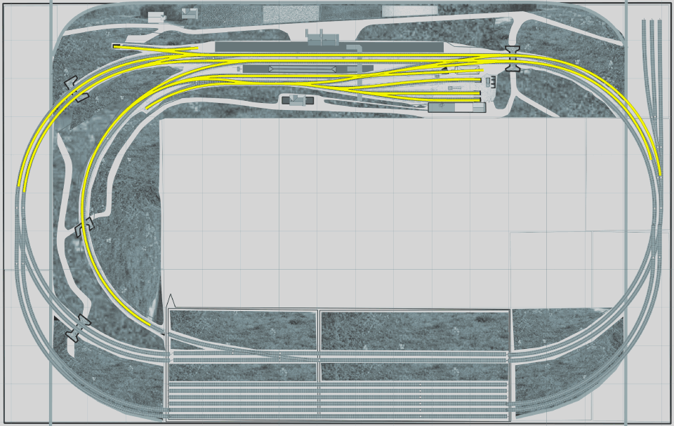 I kept your preferred straight run through the platforms, but there are now transition curves at each end of the station to provide a smooth entry into the sharp end curves. The track spacing for the main station area is at the prototype 6ft way (44.67mm centres), but I increased it to 7ft way (48.67mm centres) in the sharp end curves to ensure clearance for vehicle overhangs. On the left I moved the main line crossover round into the curves to avoid a double reverse curve and increase the clear length in the platform. This has created a nice tandem turnout for the short siding. On the right you had a sharp facing slip road in the running line, which didn't look good. I have replaced it with a half-scissors arrangement on that side. This will mean moving the signal box a little. The trailing slip road is ok in that position. Both slips are based on irregular diamonds to best match your original, so as you see all the slips roads include a transition curve to maintain alignment with the slip switches. 2_081606_420000001.png 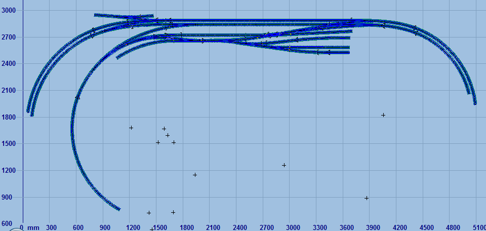 2_081606_420000002.png 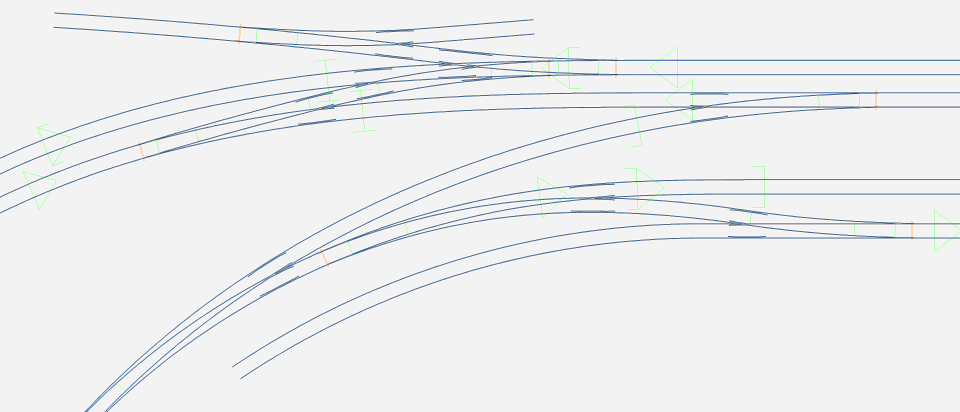 2_081606_420000003.png 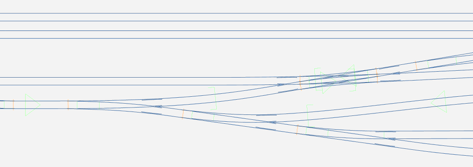 2_081606_420000004.png 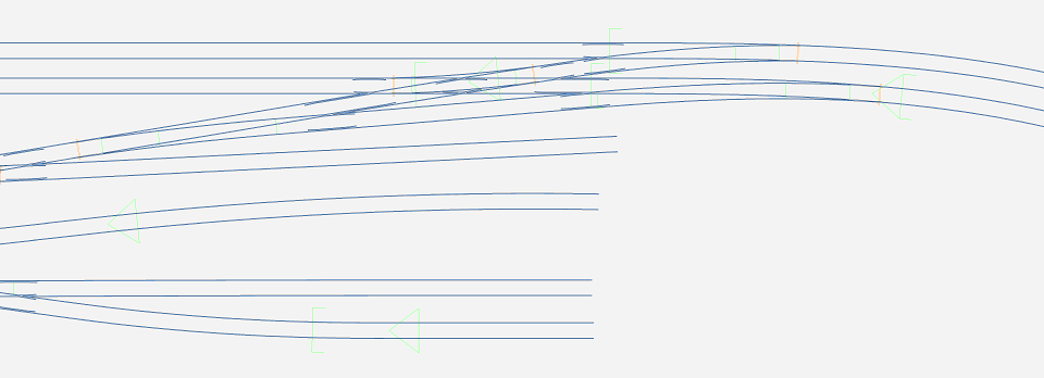 I have left the storage sidings unfinished as I understand this area is still undecided. The .box file is attached below. Note that no timber shoving has been done. Over to you for that. p.s. I see that I have forgotten to adjust the K-crossing check rails on the yard double slip. Over to you to do that. regards, Martin. |
||
| Attachment: attach_2302_2884_knuckles_knapford_unshoved_1.box 302 | |||
|
posted: 9 Jun 2016 21:45 from: Gavin Rose click the date to link to this post click member name to view archived images |
Many many thanks Martin. I won't say too much here as I already said a lot on S4 but you have my gratitude for sure. If there is anything I can help with please let me know. |
||
| Last edited on 9 Jun 2016 21:46 by Gavin Rose |
|||
|
posted: 23 Jul 2016 17:21 from: Gavin Rose click the date to link to this post click member name to view archived images |
Martin Wynne wrote: Hi Gavin... Ok I have amazed myself with the progress so far. Ever since the double junction tutorial video I have managed to do things with Templot! Might not seem much but for me a biggy. I cannot fathom how to do transition curves, slecting the option just seems to give a curve that doesn't move much when you want it, also as there are two different track centre distances for straights and curves getting them to align is a bit difficult and as a result a few areas are not even, although I'm doubting visually it will be that obvious in physical form. Getting tracks to align perfectly has been done mostly with fixed curve radii thus they don't always have the transition they should and the pegs don't always join them, rather my eye does but I'm thinking it might be ok as the curves in the areas I have done at the bottom mostly are generous. Some track joins clearly haven't been done yet but it is because I haven't figured how to marry the two different track centres. I can bodge them with fixed curve joins as I have in some areas yet the parallel track spacing I'm trying to keep best as I can. The diamond on the scenic stretch will be a single slip eventually. I've had to position some points in odd positions as they are avoiding baseboard join areas but this is no worry. The fiddle yard has so far been designed with 6 tracks, the middle two as run throughs with two lines either side for other trains, either one or two. I don't want the whole bottom section as a fiddle yard as the plan is to have the top half as a scenic run with a back scene and in future ideas the whole board is planned to be removed and another with a difference scene inserted, so for this reason all the fiddle points are kept off the middle 9foot stretch. I have found how to timber shove so that will be done later, the main thing for me is where the points will be because once this is nailed (and I think it probably is now) I can build some baseboards with the peace of mind knowing switch blades won't be bridging the gaps. I need to get the boards through the loft hatch so 2ft width is the max and it seems I might have to make a 6ft board as I'm unsure I can move the points a little to give the gap but I will look at that later, pretty sure I can. Would it be possible for you to please have a look and give pointers? I'm not asking for things to be redone but if you could maybe highlight bits with red circles and tell me what/how to fix things I'd be really appreciative and can have a go then. As I said earlier as rough as it currently is I'm amazed I have managed to do what I have so all good. 3140_231231_430000000.png 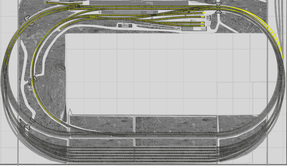 |
||
| Attachment: attach_2315_2884_knapford_2016_the_23rd_July_2016.box 299 | |||
| Last edited on 23 Jul 2016 17:31 by Gavin Rose |
|||
|
posted: 23 Jul 2016 18:01 from: Martin Wynne
click the date to link to this post click member name to view archived images |
Gavin Rose wrote:I cannot fathom how to do transition curves, slecting the option just seems to give a curve that doesn't move much when you want it, also as there are two different track centre distances for straights and curves getting them to align is a bit difficult and as a result a few areas are not even, although I'm doubting visually it will be that obvious in physical form.Hi Gavin, I'm sure I have posted about the make transition function many times, but here is a quick bit of video showing how to do it on your track plan: http://flashbackconnect.com/Default.aspx?id=mRnp5syNq72LcpXE4ek1mg2 If you search for "make transition" you will find lots of references. See for example: http://templot.com/martweb/info_files/make_trans.htm It's looking good. regards, Martin. |
||
|
posted: 23 Jul 2016 19:39 from: Gavin Rose click the date to link to this post click member name to view archived images |
Many thanks Martin. I have looked about making them but as is often with me and Templot comprehension is limited. I managed to follow the video so hopefully others can learn too, what I don't understand is why on the track below it I cannot replicate the same thing. EDIT - managed now, no idea how though! I've have made the single tracks all split from the peg and when I delete to control it gets deleted, then I press back to rectify it and it deletes a different bit of track...I end up reloading things a lot. No idea what I am doing wrong here! I have made the plan so far with only the make the control function as deleting things doesn't seem to work out well, I usually delete mystery duplicate templates after manually. I have managed to do 6 or 7 transitions so far so all good. When I try the transition thing it sometimes says it is invalid, no idea why so I try it from the other end and sometimes it works sometimes it doesn't. Either way I'm doing well in my own estimation. Thanks for your feedback. |
||
| Last edited on 23 Jul 2016 19:41 by Gavin Rose |
|||
|
posted: 23 Jul 2016 23:44 from: Martin Wynne
click the date to link to this post click member name to view archived images |
Gavin Rose wrote:When I try the transition thing it sometimes says it is invalid, no idea why so I try it from the other end and sometimes it works sometimes it doesn't.Hi Gavin, If the transition calculation fails it is almost certainly because your two templates intersect. You may need to extend the length of them to see where this is happening. This also means that if they are both curving in the same direction they cannot both be the same radius. It is mathematically impossible to create a transition curve if the centre-lines intersect. You need to adjust the radius of one or other of them until there is always a gap between them, i.e. they nowhere touch or cross over. The gap can be very small but it must exist. Here is what I mean by a gap: 2_231823_100000000.png 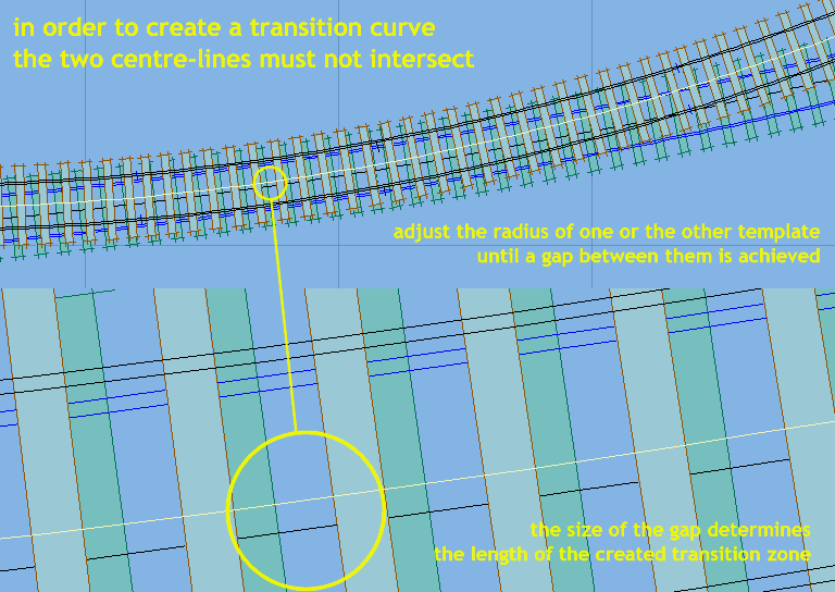 The terminology for transition curves is explained on this page: http://templot.com/martweb/gs_geometry.htm#transition I'm sorry you are having problems with this, but it is all explained in the program if you click the Help buttons, and also on this page of the web site (sorry it is so old): http://templot.com/martweb/info_files/make_trans.htm Here for example are the Help notes copied and pasted direct from Templot: Make Transition Curve from Control Template to Background Template For diagrams and a tutorial sequence showing the use of this function, please refer to the Templot Companion pages on the Templot web site at templot.com . This function creates a new control template on a transition curve alignment, which can be used to link two existing templates. The 1st radius and radial centres are taken from the existing control template. The 2nd radius and radial centres are taken from the selected background template. The existing control template is automatically stored on the background. N.B. In order to produce a usable result in all circumstances, this function uses a lower level of calculation precision than other Templot functions. Occasionally you may notice small discrepancies in the rail alignments when viewed zoomed-in to high magnification on the screen. This will be of no consequence in practical track planning. There are two possible transition curves in any given case, one of each hand. In many cases it is not obvious which hand is required. If the first one tried is not correct, the dialog which appears allows a template of the opposite hand to be easily created instead. For this function to work the following conditions must be fulfilled: 1. One of the original templates can be straight, but not both. 2. No part of the imaginary full circle or straight line which would be created by extending the track centre-line of one original template may intersect (cross) any part of the imaginary full circle or straight line which would be created by extending the track centre-line of the other original template. 3. If the two imaginary circles are completely separate, the result will be an S-curve transition. 4. If the smaller imaginary circle is completely contained within the larger imaginary circle, the result will be a C-curve transition. 5. If the two circles are just touching (for example if the two templates have been aligned at a common boundary using the peg and notch functions), the result will be a zero-length transition at the boundary. 6. The resulting transition must not be more gentle than the current [ max spiral ] setting permits. For a C-curve transition, this means that there must be a sufficient difference between the two radii. For more information click the [ program > expert > transition maths > max spiral... ] item on the [ program panel ] menus. The new control template will have a 1 chain (66ft) (scale) length of 1st radius before the transition start position, and a similar length of 2nd radius beyond the transition end position. The final task of extending or shortening the new template at each end, and/or doing likewise with the original templates, in order to position the template boundaries and create a full linking template between them, remains for you to do. (Put the fixing peg at the opposite end and then use the F4 mouse action to adjust the overall length). Often when using this function the original templates are dummy templates created solely for the purpose. These are then deleted and the new transition template is extended at each end to replace them. If the [ delete the original templates ] box is ticked, this will happen automatically when you click the [ yes - continue ] green bar to accept the new transition curve template. If one of the original templates is itself containing a transition curve a dialog will appear asking how you want to proceed. The new transition curve can be matched to 1st or 2nd radius on the original template, or matched to the radius at the current position of its fixing peg. If this is within the transition zone, you will need to shorten the original template to this position in order to make a correct boundary with the new control template. Use the [ do > snap to peg ] menu item, possibly preceded by [ template > swap end-for-end ]. Repeat [ template > swap end-for-end ] on the original template if necessary after creating the new transition (for example if the original template is a turnout). This function is not available if one of the original templates contains a slew. If a slew is needed it can be applied after creating the transition curve. regards, Martin. |
||
|
posted: 30 Jul 2016 01:05 from: Gavin Rose click the date to link to this post click member name to view archived images |
Thanks Martin, sometimes I am replying the same as on S4 but not always. I think I am getting the hang of things better now as the success rate is much higher. What I have done since is completely redesign the fiddle yard because since making it I don't like how all the scenery space is eaten up so I have decided go just go with a standard fiddle yard in the middle and do away with those double junctions at each extremity. What I have found though is that one of the locations I have always wanted to model is a yard with a rough fiddle type layout so I have been creating that and this instead will technically serve as another layout in a way. It's compromise either way but this seems good to me as I don't have to have a masd of Plywood staring at me unmodelled - something I see as a waste when space is at a premium. |
||
| Last edited on 30 Jul 2016 01:08 by Gavin Rose |
|||
| Please read this important note about copyright: Unless stated otherwise, all the files submitted to this web site are copyright and the property of the respective contributor. You are welcome to use them for your own personal non-commercial purposes, and in your messages on this web site. If you want to publish any of this material elsewhere or use it commercially, you must first obtain the owner's permission to do so. |