Templot Club Archive 2007-2020
|
|||
| author | remove search highlighting | ||
|---|---|---|---|
|
posted: 16 Feb 2018 04:15 from: Martin Wynne
click the date to link to this post click member name to view archived images |
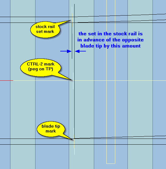
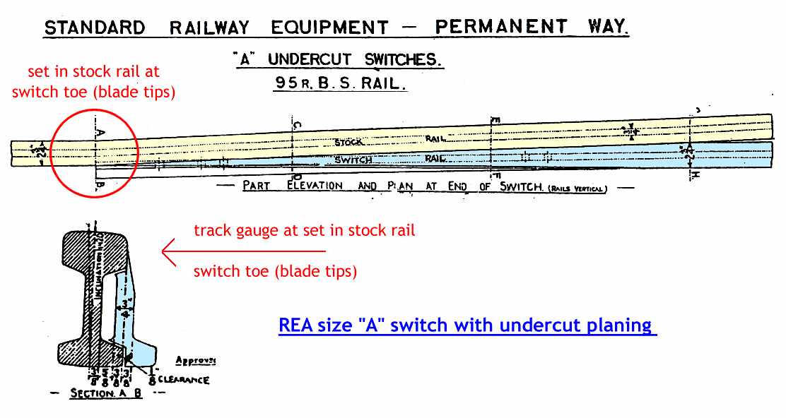
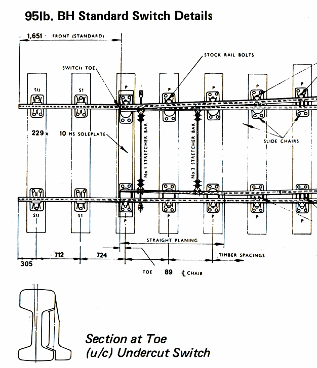
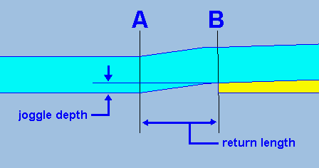
This is a temporary re-posting from bits of the old "real track" web page. I have added some additional diagrams to the original 2001 text. I was not really ready to post this and I feel I'm being pressured into posting stuff before I'm ready. I'm sorry about the formatting and thrown-together look of it. All this old stuff will be reappearing in the Templot Companion in due course, properly updated for Templot2 with new diagrams and videos and explanations. But not yet. p.s. The hobby was massively ill-served by an article in MRJ about 20 years ago which mixed up "straightcut" switch planing with the geometry of straight switches. All switches can be either straightcut or undercut planed (or chamfered or other) regardless of whether they are straight, semi-curved, or curved switches. Martin. red_pointer.gif  These notes apply to UK-pattern bullhead track only. These notes apply to UK-pattern bullhead track only.Setting the Curved Stock Rail The diagram below shows the position of the set (bend) in the turnout-side (TS) stock rail, which matches the planing angle on the switch blades and is needed to ensure a correct track gauge through the turnout road of the switch. Templot puts a mark across the curved stock rail at the position of the set, as shown below (for a left-hand switch). stock_set.gif In Templot the set is slightly in advance of the tip of the opposite blade, as shown, and in order to ensure that the geometry works correctly the TP peg position (CTRL-2) is in advance of the blade tip by half this amount. The diagram shows the set mark at the minimum amount of set advance. There is no harm in having a little more in models to help protect the mating blade tip from wheel damage. However, an excessive set advance should be avoided as this can cause a knock to the wheels of trailing traffic. Often for facing traffic, and on all GWR switches, the set is replaced with a joggle. Undercut Switch Blades: The first diagram below shows the left-hand stock rail and switch blade for a left-hand undercut pattern switch with a plain unjoggled stock rail. This is the type of blade planing most often modelled because it requires only a plain set in one stock rail. A set (bend) is put in the turnout-side (TS) stock rail at the toe of the switch (blade tip) to match the planing angle on the switch blade. The switch blade is planed (machined) to a sharp tip, and profiled down below the top of the stock rail to fit under the head of the stock rail (undercut). This is in order to have sufficient strength at the tip. Such a blade acts only as a guide to the wheel flanges for the first part of its length and does not actually support the weight of wheels running onto it until they have reached some way along it. Undercut switches can often be identified in photographs because the shiny top of the open blade stops some way short of the tip. joggle-3.gif
2_152258_310000000.png
2_152258_310000001.png
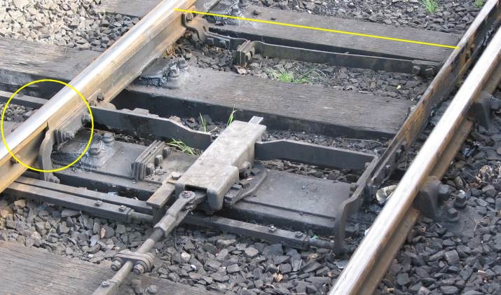
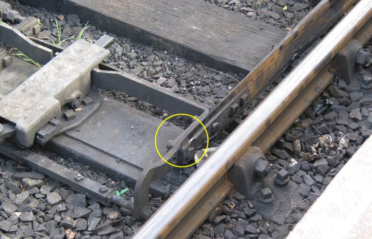
Here are some photos of an undercut switch. You can see from the shiny marks on the top of the blade that it starts to take some part of the wheel load at about the position of the second stretcher bar. Up until that point it is simply guiding the wheel flange, and is dull on top:
2_171152_120000000.jpg
You can see that the tip is very thin, and if continued up to the top of the stock rail it would be a knife edge.
Straightcut Switch Blades with Joggled Stock Rails : When a more robust switch is needed, both of the switch stock rails are joggled outwards by a small amount to create a housing for the switch blade tips and so protect them from wheel damage. This next diagram below shows this alternative straightcut pattern switch with a joggled stock rail. joggle-1.gif Instead of a plain set in the stock rail at B, it is joggled sideways between positions A and C, with the maximum deflection from its previous unjoggled alignment being at the blade tip position B. In bullhead track the joggled section is always created by bending the rail rather than by machining a notch in it. The switch blade is planed to a blunt tip (straightcut), to a thickness corresponding to the amount of joggle, which has been exaggerated in this diagram for clarity. Apart from a rounded corner at the tip the blade is the full height of the stock rail and plays its part in supporting the wheels along its full length. A straightcut switch can often be identified in photographs by showing a shiny top on the open blade all the way to the tip. joggle-2.gif In defining a joggled switch, two dimensions are needed. The joggle depth (sideways deflection) at B, and the joggle return length in front of the blade tip between positions A and B, in which the rail returns to its normal alignment. (The length between B and C always corresponds to the planing length for the switch blade). These dimensions need to be entered when creating a custom joggled switch in Templot. Having entered joggle dimensions for your custom switch, you can choose whether to actually use the joggles for an individual template by means of the joggled stock rails option tickbox. 2_152321_250000000.png 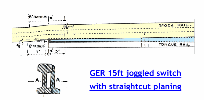 Here is a photo of a GWR joggled switch with straightcut planing. Notice the thicker more robust nature of the blade tip, and that it is full height and shiny all the way to the tip. Notice also that the depth of joggle in the stock rail is very small in relation to the rail width. It is not easy to create such a joggle in models. gwr_joggle2.jpg 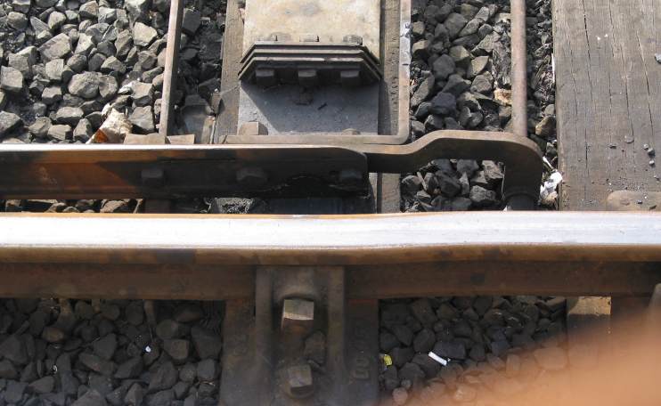 Prototype notes: REA and straight loose-heel switches can be either joggled or not - normally joggled switches are used only in facing positions on running lines. In trailing positions there is a danger of rough running when wheels hit the joggle return length on the open switch blade side, most severely when the main-road is curved. However, all GWR and BR(WR) switches are joggled. For REA switches the joggle depth is 3/8" (0.375 inches) and the joggle return length is 6 inches. For older pattern straight loose-heel switches these dimensions vary, but are usually similar. For GWR old-pattern switches the joggle depth is 3/8" (0.375 inches) and the joggle return length is 4 inches. The later GWR and BR(WR) curved flexible switches have a less severe joggle, the joggle depth is 1/4" (0.250 inches) and the joggle return length is 6 inches. These joggle depths are barely perceptible in the smaller model scales. A 1/4" joggle is only 3 thou (0.003 inches) (0.08 mm) in 4mm/ft scale. Some modellers prefer a more pronounced joggle, and Templot provides for this with the generator > overscale joggles menu option, which creates a joggle depth of 3/4" (scale). Visitors to the Severn Valley Railway steam heritage line in Kidderminster UK can very easily observe the difference between joggled and unjoggled switches. In platform 1 the engine release turnout at the buffer stops has an REA semi-curved flexible switch with undercut-pattern switch blades (no joggle). In platform 2 the engine release turnout has a GWR curved flexible switch with straightcut-pattern blades and joggled stock rails. The very much more robust nature of the blade tips in the latter case is very evident. |
||
|
posted: 16 Feb 2018 09:06 from: Tony W
click the date to link to this post click member name to view archived images |
Hi Martin. My query arises from this section of British Railway Track as always. 2151_160347_490000000.jpg 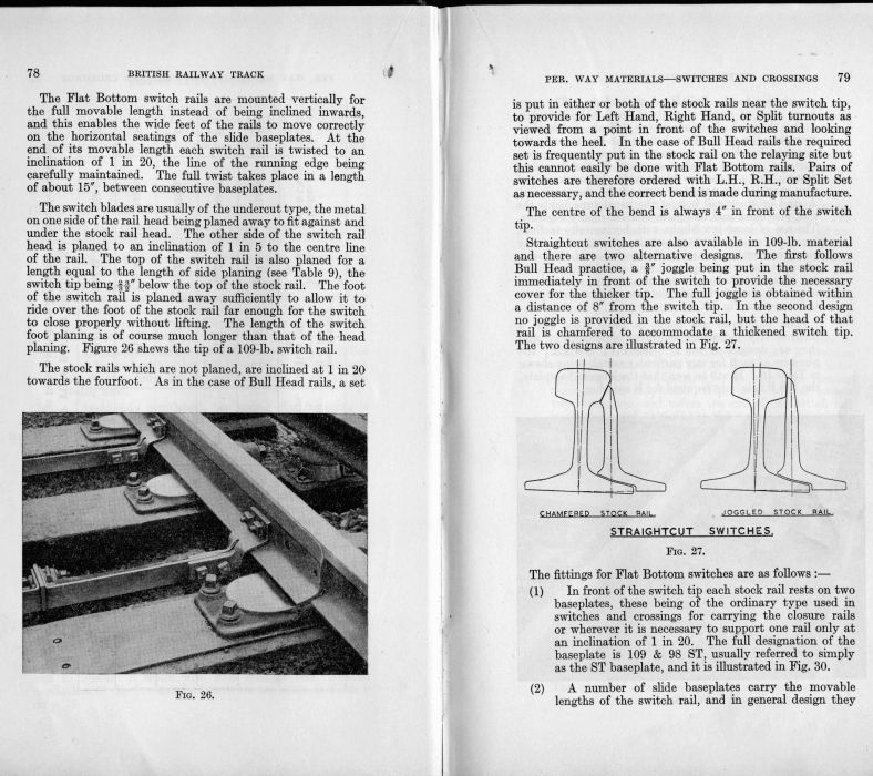 Second Paragraph page 79 of the 1956 edition. The previous paragraph states that this applies to both Bull Head and Flat Bottom rails. The 1964 edition states the same at the bottom of page 88. This would imply without exception. However railways being what they are, I am quite prepared to believe that there were variations among railway company practices. Indeed I would be surprised if there weren't. Fully agree with you over the confusion arising between the various types and descriptions of switch blade and this is something I intend to address in my track building topic on the S4 site shortly. Finally, I apologise if what I have done has made you feel at all pressurised to do anything, that was not the intention. My aim is to equip people with the knowledge to make better choices as to how they go about building trackwork and hopefully avoid most of the common pitfalls. Regards Tony. |
||
|
posted: 16 Feb 2018 13:01 from: Martin Wynne
click the date to link to this post click member name to view archived images |
Tony W wrote: Hi Martin.Hi Tony, Thanks for jogging (or even joggling That reference has been removed from BRT4 (1971), as also has most of the stuff about straight and semi-curved switches, and straightcut or undercut planing. It is all about the curved switches and chamferred planing for the BS-110A and BS-113A FB inclined designs, and the later vertical designs. The reference to 4" makes no sense, but I'm not going to say any more just now about the position of the set, because it is a nice sunny day and I have spent enough of it already in front of the computer. But I shall return to it later as there is a lot more to say about this, both model and prototype. However, I'm sorry to disappoint you in that I'm not intending to change the set mark on the Templot templates. The position marked does not correspond to any prototype drawing I have ever seen, but it is necessary for it to be where it is in order for the switch geometry to work correctly and for a correct track gauge through both roads. cheers, Martin. |
||
|
posted: 16 Feb 2018 17:40 from: Tony W
click the date to link to this post click member name to view archived images |
Hi Martin. Fair enough for me. Indeed, we have just taken the opportunity to take the dog for a walk in the sun along part of the old Cromford canal. My wife wanted to drag me away from the computer screen for a while. Regards Tony. |
||
| Please read this important note about copyright: Unless stated otherwise, all the files submitted to this web site are copyright and the property of the respective contributor. You are welcome to use them for your own personal non-commercial purposes, and in your messages on this web site. If you want to publish any of this material elsewhere or use it commercially, you must first obtain the owner's permission to do so. |
