Templot Club Archive 2007-2020
|
|||
| author | remove search highlighting | ||
|---|---|---|---|
|
posted: 5 Aug 2008 06:50 from: Bob Hobbs click the date to link to this post click member name to view archived images |
Hi all I have had Templot for less than 3 days. It does most of what I want to do so far. Martin has been patient and helpful but suggested that this is the place to get help. I work in HO, Canadian Pacific in Southern British Columbia, mid 60's. I am running Templot version 0.82.d on WindowsXP. My first question is I hope not too challenging - it has me stumped. I am trying to model a portion of a large Wye in Caslegar BC I have cut down a 5 double ended siding on the prototypes straight side to 3 tracks. I need this to be curved with the sharpest curve in the 21" radius range. I am using two curved switches at either end of this trackage. At one end the switches are connected to one diverging leg of a wye switch, at the other end they are connected to the diverging leg of a #7 16.5' standard switch. I can create a series of templates from the diverging leg of the #7 to a right hand curved switch to a connecting curve on the diverging leg to the diverging leg of a left hand curved switch to the diverging leg of the wye. I can easily connect a left hand curved switch to the main leg of the left hand switch and a right hand curved switch to the main leg of the right hand curved switch. What I cannot figure out is how to connect the diverging leg of the second right hand switch to the diverging leg of the second left hand switch and the same for the main legs of the same two pair. It would be easier to do a sketch, but I do not have access to a scanner. I could provide a jpeg of the rough plan from XTrackCad if that would help. This is far from prototype practice I realize. Bear with me please, space is a premium and this wye is critical to the operations I have planned. Bob Hobbs Ottawa, Canada |
||
|
posted: 5 Aug 2008 12:41 from: Martin Wynne
click the date to link to this post click member name to view archived images |
Hi Bob, Welcome to Templot Club. I could provide a jpeg of the rough plan from XTrkCad if that would help.Yes please, that would help a lot. Sorry, but your explanation is almost impossible to follow for those of us in the UK because of the differences in trans-pond terminology. As far as I know, you mean: double-ended siding = loop. wye = track triangle, as sometimes used for turning locomotives. wye switch = Y-turnout. switch = turnout. You will get in a total muddle in Templot if you follow the US practice of referring to an entire turnout as a "switch". In Templot and the UK, a switch is a "set of points" and refers only to the moving points part of a turnout, not the whole thing. But UK modellers are equally guilty of confusing the issue, by referring to an entire turnout as a "point". Unfortunately there's not much I can do about all this. Templot uses the proper p.w. engineering terms as far as possible. Here's the diagram again from the "making a start" page in the docs: startup_pad.png  If you can provide a screenshot of what you mean I'm sure we can help. That could be from XTrkCad or a rough freehand sketch with the mouse in any drawing package. regards, Martin. |
||
|
posted: 5 Aug 2008 14:01 from: Nigel Brown click the date to link to this post click member name to view archived images |
HI Bob Am I right in thinking that you have a number of parallel (curved) tracks, in your case 3, which converge at each end to a single track via a number of turnouts, in your case 2 (plus 1 for the main line of the Y), that you can connect the first (inner) track to the appropriate road of the turnout at each end, but that you cannot see how to connect up the remaining roads of the turnouts with appropriate tracks parallel to the first (curved) track? cheers Nigel |
||
|
posted: 5 Aug 2008 20:20 from: Bob Hobbs click the date to link to this post click member name to view archived images |
Nigel Brown wrote: Am I right in thinking that you have a number of parallel (curved) tracks, in your case 3, which converge at each end to a single track via a number of turnouts, in your case 2 (plus 1 for the main line of the Y), that you can connect the first (inner) track to the appropriate road of the turnout at each end, but that you cannot see how to connect up the remaining roads of the turnouts with appropriate tracks parallel to the first (curved) track? Hi Nigel That is the idea. I realize that the tracks cannot be parallel but I can get them approximately parallel. I had a go at joining them last night. With the time differential this will probable take a while unless there are some North Americans listening in that can help. I am going to add the .box file for what I have so far, a screen shot from XTrkCad, and the .xtc file for anyone with XtrkCad. XtrkCad is good for rapid what-ifs but falls down in getting anthing resembling templates. Both pieces of software have a place in my design efforts. XtrkCad does a great job in designing benchwork as well. Just another useful tool in the planning process. For free it does a lot. While I'm at it, is there a tutorial in creating an actual Y-turnout or wye switch as I know it? Bob Hobbs Ottawa, Canada |
||
|
posted: 5 Aug 2008 20:50 from: Martin Wynne
click the date to link to this post click member name to view archived images |
Bob Hobbs wroteI am going to add the .box file for what I have so far, a screen shot from XTrkCad, and the .xtc file for anyone with XtrkCad. Hi Bob, To attach files you must post them via the forum web site, you can't post them via email as you have been doing. There's a link to the forum web site at the top of every email message. Note also that if you post attachments you are limited to one file per message. Just post additional messages to send several files. If one of the roads in your Y-turnout is a running line, then you don't need a detailed tutorial. Just give the turnout some contraflexure (negative curving) using the F6 mouse action. Unless it forms part of a curved crossover, it's usually better with such contraflexure to use a curviform type of V-crossing. The best way to understand all that is to watch a video. See: starter video page which includes such a Y-turnout in a running line. If it's not a running line, and you want a true symmetrical Y-turnout, there is a static tutorial for that at: Y-turnout tutorial although it is 7 years old and in need of some updating for later versions of the program. regards, Martin. |
||
|
posted: 5 Aug 2008 21:09 from: Bob Hobbs click the date to link to this post click member name to view archived images |
Martin Wynne wrote:I could provide a jpeg of the rough plan from XTrkCad if that would help.Yes please, that would help a lot. I will forward one or more files this evening. With the 5 hours time differential this may take a while. Sorry, but your explanation is almost impossible to follow for those of us in the UK because of the differences in trans-pond terminology. As far as I know, you mean:Your translation is correct. I lived in the UK for 3+ years in the mid-70's and had forgotten how the 'common' language can get in the way sometimes. The 'track triangle' in this instance in reality is quite large with the longest arm being close to 3500' long. I am trying to compress this arm into a curved part with an approximate radius of 35 inches (HO so fairly tight) If you can provide a screenshot of what you mean I'm sure we can help. That could be from XTrkCad or a rough freehand sketch with the mouse in any drawing package.I'll send both the XTrkCad and my attempt in a .box file. Bob Hobbs Ottawa, Canada |
||
|
posted: 6 Aug 2008 10:37 from: Bob Hobbs click the date to link to this post click member name to view archived images |
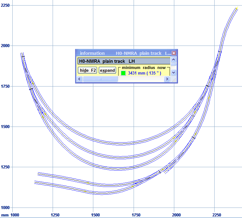
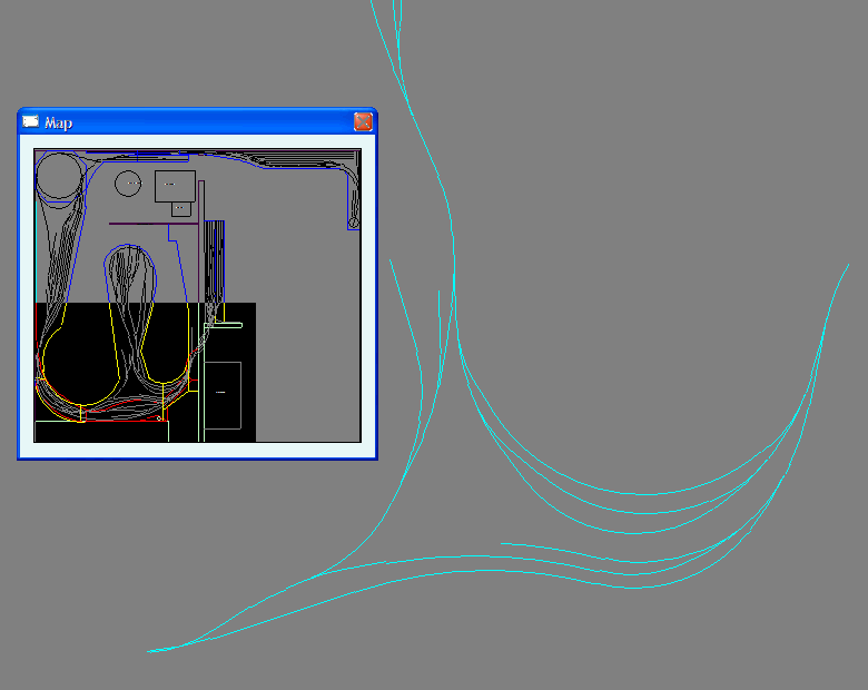
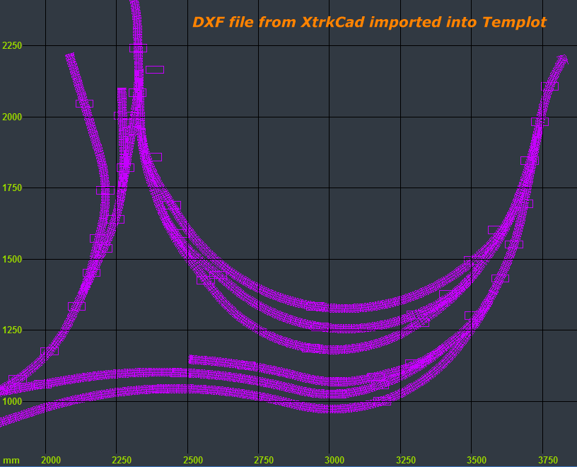
Hi Gang As promised three files have been uploaded to the Yahoo Files section under folder BobHFiles. ### edit: Bob, not all members of Templot Club are members of the Yahoo group. I have copied your files to the Templot Club web site and linked them in your text below so that everyone can access them. I've also added screenshots below for those who do not have Templot or XtrkCad programs. Martin. ### One is the box file for where I am in Templot . The second is the xtc file of the layout in XtrkCad for those of you that can access it. (click the links above with right mouse button, then select Save Target As... or Save Link As... ) The third is a Word document containing a screen print of the Castlgar Wye as I have poorly drawn it in XtrkCad. It is the best I can do with the limitations of this software. .box file: castlegar3.gif  .xtc file: castlegar3_xtc.png  .dxf from Xtrkcad imported into Templot background shapes: castlegar3_xtc_dxf.png  I want to use Templot to get the trackwork as smooth as I can and produce the building templates. Thanks in advance for any help coming my way. Bob Hobbs Ottawa, Canada |
||
|
posted: 6 Aug 2008 10:57 from: Bob Hobbs click the date to link to this post click member name to view archived images |
Hi All. I have uploaded 3 files to the files section. BobHFiles A box file to show where I am. While I have an attempt at joining the ends of the loops they do not match exactly. An xtc file for the whole setup as I have it now. A Word doc with a prnt scrn of the Castlgar Wye for those that do not have XtrkCad. Any help, suggestions is appreciated. Once I learn how to complete these loops I can apply the technique to other parts of the layout. Bob Hobbs Ottawa Canada. |
||
|
posted: 6 Aug 2008 11:07 from: Martin Wynne
click the date to link to this post click member name to view archived images |
Hi Bob, If you post messages directly on the forum web site instead of via email, they will appear instantly and you won't suffer the delays. There's a link at the top of every email, with this message: Please use the above link to reply to this message. Replies by email will be subject to delay.The delay is because if you post by email your message has to wait until I'm around to steer it into the system. Please click the link provided in the email and then post your message on the web site. Just click the "Reply with quote" or "Reply blank" buttons, or enter your reply in the "Quick Reply" box at the bottom of the page. Thanks. regards, Martin. |
||
|
posted: 7 Aug 2008 23:39 from: Martin Wynne
click the date to link to this post click member name to view archived images |
Bob Hobbs wrote: What I cannot figure out is how to connect the diverging leg of the second right hand switch to the diverging leg of the second left hand switch and the same for the main legs of the same two pair.Hi Bob, The function you need to create these loops is make transition. There's a video showing it in use. Go to the video list, read the notes, then scroll down to "using 'make transition' into a parallel platform". The video is silent, but there is a static tutorial for 'make transition', explaining what is going on. It's a bit dated, instead of the peg and notch functions you can use the make branch track and make split at peg functions to set up the initial dummy templates. The 'make transition' function is also much used in the longer video "overlaid track on a scan" (a classic H0 design which you may recognise). p.s. you mentioned that you are working to 21" radius, but in your .box file the outer loop is only 18" radius. Is that ok? regards, Martin. |
||
| Please read this important note about copyright: Unless stated otherwise, all the files submitted to this web site are copyright and the property of the respective contributor. You are welcome to use them for your own personal non-commercial purposes, and in your messages on this web site. If you want to publish any of this material elsewhere or use it commercially, you must first obtain the owner's permission to do so. |