Templot Club Archive 2007-2020
|
|||
| author | remove search highlighting | ||
|---|---|---|---|
|
posted: 26 Oct 2009 11:32 from: Josh C click the date to link to this post click member name to view archived images |
Hello all, While I had the program up and running yesterday trying to make a three way for a friend, I decided to draw up a plan I had been meaning to do for a while, The idea is to have it as a tester layout for hand built point construction, before I dive into something long term, The plan has been drawn up in 00 finescale, but I am considering trying it in p4 as well, but am not sure yet with all the pros and cons to take into account. My may concern is how the timbers are arranged around the point work, If someone could run there eye across it and check it is all "do-able" that would be fantastic or any pointers for improvements etc Thanks again Josh |
||
| Attachment: attach_673_964_New_Idea.box 357 | |||
|
posted: 27 Oct 2009 15:39 from: Martin Wynne
click the date to link to this post click member name to view archived images |
Hi Josh, I'm afraid you have made a common mistake with tandem turnouts. The two switches are not far enough apart. As a result there is insufficient space for the second switch blade to open behind the first switch rail: 2_270959_040000000.png 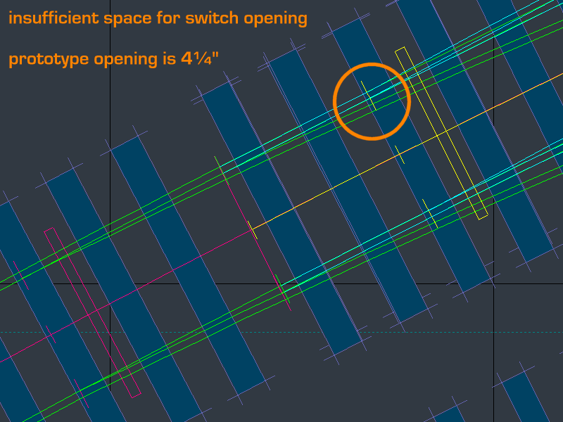 On the prototype the blade opens by 4.1/4" which scales to 1.42mm in 4mm/ft scale. Even in P4 it's advisable to increase that to 4.1/2" (1.5mm) to ensure adequate flange clearance all along behind the open blade on flexible switches. In 00-SF or EM you will probably need even wider switch opening. So the absolute minimum offset (gauge-face to gauge-face) is 4.1/2" opening + 2.3/4" rail-width = 7.1/4" (2.42mm). In practice the prototype needs rather more than that to accommodate the slide chair and a bolted half-chair on the timber. A good rule of thumb is to make the minimum offset equal to 3 rail-widths, i.e. 3 x 2.3/4" = 8.1/4". Or in other words, the space between the rails at the switch tip should not be less than 2 railtop-widths. You could get away with a fraction less in a model with careful construction, but the above rule will give you room to fit the chairs in a prototype fashion. If you can allow a bit more space, so much the better. Michael Davies kindly uploaded a great many excellent detail shots of pointwork, including this one of the second switch tip in a tandem turnout (FB): 1679_261345_190000003.jpg 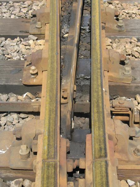 Click the picture and follow the links to see the high-res image full screen. regards, Martin. |
||
|
posted: 27 Oct 2009 18:13 from: Josh C click the date to link to this post click member name to view archived images |
Would someone consider fixing it for me? | ||
|
posted: 10 Nov 2009 23:28 from: Martin Wynne
click the date to link to this post click member name to view archived images |
Hi Josh, Here's an improved version. I changed the B6 to an A7 to get a better arrangement of the V-crossings. I've done a suggested timbering layout, but of course there are many possible arrangements. The .box file is attached below. If you hold down the SHIFT key and run the mouse down the name labels, you can see how the partial templates are made up. Notice how the timbering under each V-crossing is part of the same template. This ensures that the special crossing chairs will fit the vee rails and wing rail fronts in the proper places. 2_101822_290000000.png 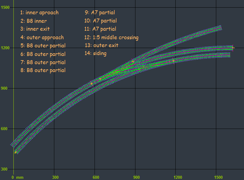 2_101821_140000000.png 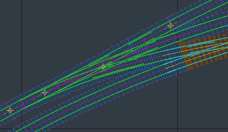 Here's the printed result: josh_tandem_print.png 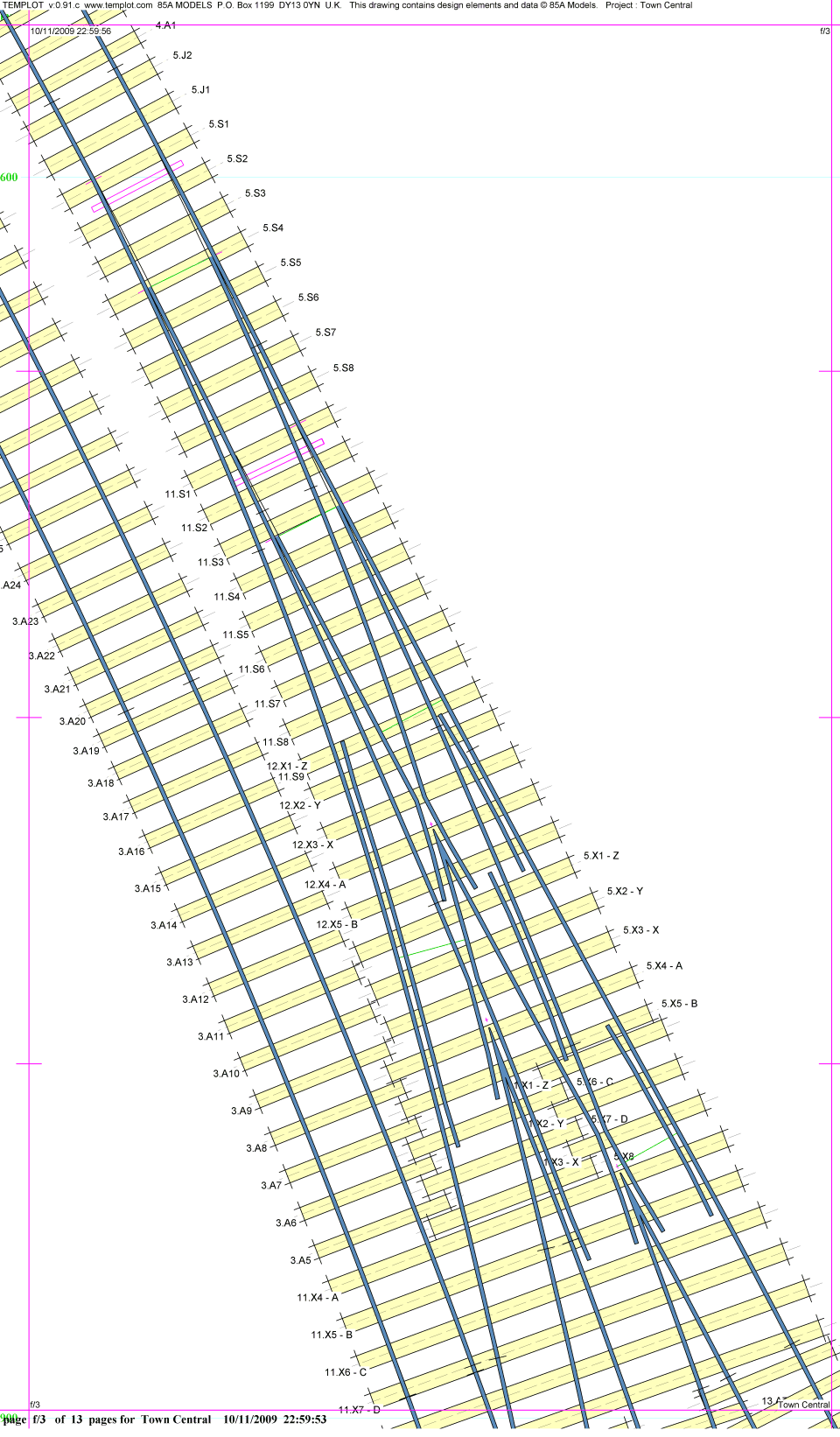 regards, Martin. |
||
| Attachment: attach_682_964_tandem__for_Josh.box 314 | |||
| Please read this important note about copyright: Unless stated otherwise, all the files submitted to this web site are copyright and the property of the respective contributor. You are welcome to use them for your own personal non-commercial purposes, and in your messages on this web site. If you want to publish any of this material elsewhere or use it commercially, you must first obtain the owner's permission to do so. |