| Templot Companion | search | remove search highlighting | if the A-Z Index tab is missing click here |
Working with slips
An article about how slips are usually worked from the signal box. The practice of some prototype companies may vary.
Diagram 1:
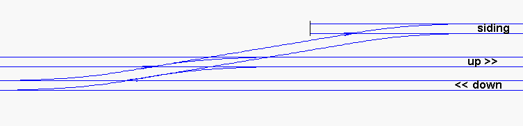
Diagram 1 shows a typical use for a single-slip as part of a slip crossover. A siding on the up side of the running lines makes a trailing connection with the down line via a single slip in the up line. This way of accessing a siding or goods yard avoids the need for facing points, which are frowned on in running lines for safety reasons and have to be fitted with facing-point locks in passenger lines.
The siding is arranged with a short trap spur (or it could simply be a set of catch points as the trap) to keep any runaway vehicles in the siding clear of the running lines.
Diagram 2:
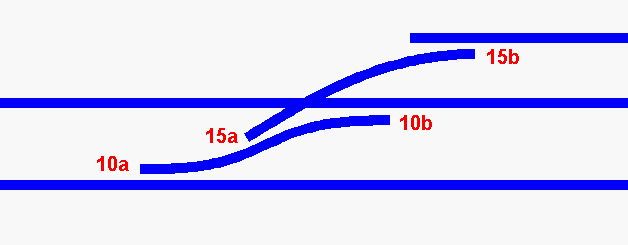
Diagram 2 shows how this might look on the signal box diagram. The siding connection is worked with two levers, numbered here 10 and 15. (They are not consecutive numbers because it is likely that between them in the lever frame would be the levers for the ground disc signals controlling the movements over this slip crossover.)
Lever 10 controls both sets of point blades 10a and 10b simultaneously, i.e.one turnout and the opposite end of the single slip.
Or in model terms one switch on the panel works both point-motors 10a and 10b. If the point-motors being used were strong enough, it would be possible to use only one point-motor with a mechanical linkage to each set of blades.
Likewise lever 15 controls both sets of point blades 15a and 15b simultaneously, again one turnout (or trap points) and the opposite end of the single slip.
The diagram shows how the point blades would lie when both levers are normal in the frame, i.e. for normal up and down running. Note that the single-slip normally lies with one set of blades set for the straight road (10b), and one set of blades set for the curved slip road (15a).
The siding would be shunted as follows:
A locomotive on the down line wishing to enter the siding would first draw forward beyond the turnout on the left. Both levers 10 and 15 are then pulled changing all 4 sets of blades. The locomotive can then set back across the diagonal of the slip into the siding. On the model, because all 4 blades have moved, all V-crossing (frog) polarities will be correct for this move.
A locomotive on the up line wishing to enter the siding would first draw forward beyond the slip to the right.
Lever 10 only is then pulled, changing 2 sets of blades 10a and 10b. The locomotive can then set back through the slip onto the down line, and again all V-crossing (frog) polarities will be correct. Finally lever 15 is also pulled so that the locomotive can draw forward across the diagonal of the slip into the siding, and all V-crossing (frog) polarities will be correct again.
The lever interlocking in the signal box would prevent lever 15 being pulled if lever 10 has not been pulled first. And lever 15 must be returned to normal before lever 10 can be returned to normal. This means that there is never a time when the route is set for both straight roads across the slip.
In practice, of course, it is likely that rolling-stock in the siding would need to be shunted into or out of a train on the running lines, such as a pick-up goods train. For this to be possible for an up train, an additional trailing crossover is needed to permit running-round. This would most likely be situated off to the right of this diagram.
Remember when checking the polarities that every V-crossing (frog) is isolated completely from the surrounding rails by means of 4 rail gaps, and that the polarity of the V-crossing (frog) at one end of the slip is controlled by a changeover switch linked to the blades at the opposite end of the slip.
For DCC or if only one DC controller is in use, no other gaps are essential.
If two or more DC controllers are in use, running the up and down lines independently, it will also be necessary to isolate the outer stock rail of the slip on the section feed side, and to provide an additional changeover switch on lever 10 to switch it between the up and down sections. Although located on the up side, the siding should be part of the down line electrically, with a section switch connecting it to the down controller.
Martin.
© 4-Aug-2000
link to this page: https://85a.uk/templot/companion/working_with_slips.php