Templot Club Archive 2007-2020
|
|||
| author | remove search highlighting | ||
|---|---|---|---|
|
posted: 22 Oct 2011 18:55 from: leo_sandstrom
click the date to link to this post click member name to view archived images |
Hi After having a look at the available templates for download I thought Id give it a go to produce a turnout based on a specific american prototype. Please see the attached PDF for the prototype info. I started off with a generic american template that I found on this forum and tried to modify it. I start off by having the generic template active and pick slot 8 for the remake. I answer yes, adopt the switch from the control template for slot 8. Then I press custom again and enter new or modified data. I name the new turnout: Conrail #8 16'-6" switch for bolted 119lb rail (1979 drawings) Next question is the type of switch, thats easy, its a straight switch. Next is the lead length to heel. This is explained as: "This is the distance from the tip of the blade (switch rail) to the point known as the "heel". This point is used in the calculation of the turnout radius." That should be 16' 6", giving me 198 inches. Looking good so far. Offset at the heel: 6,25 inches, I didnt actually get this measurement from the drawing, I just remember it as being standard somewhere... I might be wrong though. Now comes the stock rail joint to toe, and its explained as follows: This is the switch front distance from the stock rail joint at the left end of the turnout to the "toe" (blade tips). For GWR switches this dimension is normally 64 inches, elsewhere it is usually 65 inches. There are normally 2 standard sleepers occupying this space. This is where it starts to get tricky, on my prototype turnout and american rail in general the joints are staggered. I guess Ill just compromise and skip it, setting it to the shortest distance in my drawing. 2094_221300_480000000.png 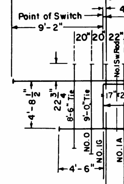 Looks like I have it right there, 4' 6" = 54 inches Next is length of switch rail blade, this is also hard since according to the prototype drawing they are not of the same length. To avoid rail joint marks that are wrong anyway I just enter 0 for this one and skip it. Length of stock rail from joint is next. While both stockrails are infact 39' long, the problem is that they are staggered, so if I enter something here it will still make one of them wrong. Ill just skip it and use the prototype drawings later when I add joint bar details. Next is joggled stock rails, and I just skip it. To be honest I dont know if its supposed to be used or not. Here comes my favorite part, timber spacings, this is actually one of the reasons I choose to redo this switch, I want the timber spacings throughout the switch to be visible. Might as well get this correct since Ill use a CNC mill to cut the timbers meaning I got excellent tolerance. (and its a nice and visible feature to) First it asks if the front section is timbered or sleepered. Apparantly the dimensions differ alot in the UK, however as far as I know they are the same in the US. I pick plain track sleepers. Now it asks for spacing from toe to first sleeper. Luckily it states J1, and by starting another templot session and showing timbers on a turnout I manage to find that it is infact this timber: 2094_221327_050000000.png 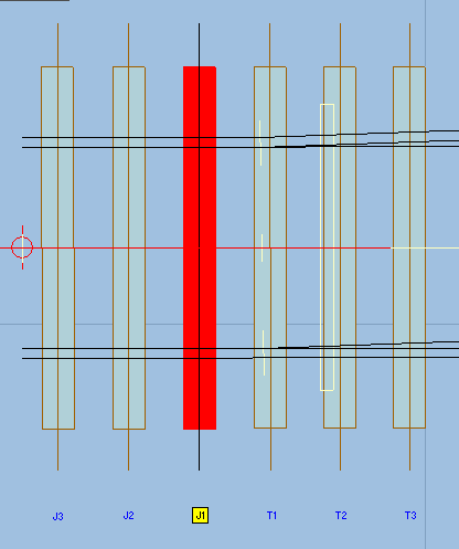 Going back to my prototype drawing I assume the question is in relation to the center of that timber. 2094_221328_490000000.png 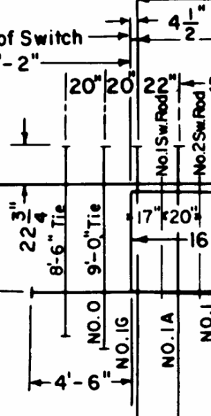 According to my drawing I get 20 inches - 4,5 inches = 15,5 inches. Perfect, moving on. Next I have to enter the spacing to the next sleeper, I presume we are talking to the left here, thats easy, 20 inches according to the drawing. Then I get a quesion for another sleeper, since I only want two I enter 0. (having read somewhere that a 0 terminates the list. It did not, but to prevent them from appearing I entered 0 on the J3-J5 timbers. Next question is spacing forward from toe to first timber, that should be easy, according to the drawing above that should be 4,5 inches. Now, I have to input more timber data, since the timbers have varying cc I made a small picture to keep track of them: 2094_221338_310000000.png 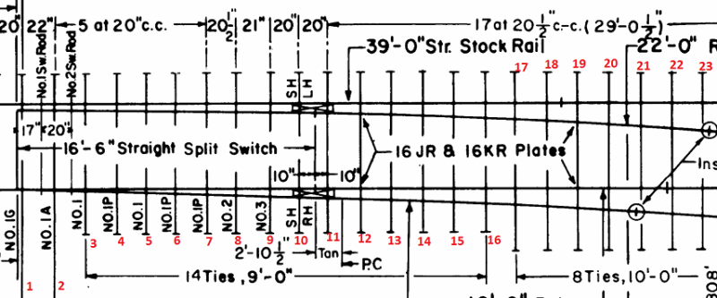 Tie 1 to 2 spacing, 22 inches. Then 20 inch cc up to tie 7. Then 20,5 inches between 7 and 8. 8 to 9, 21 inches. 9 to 11, 20 inches on both. Then 20,5 inches up to tie no 28. 2094_221345_540000000.png  At tie 28 the spacing changes to 20,75 inches and continues like that to tie 36. Then it gets tighter and 19,5 inches up to tie 45. However, after pressing ok on tie 41 I just get back to the following dialog: 2094_221349_370000000.png 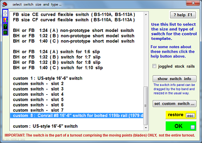 2094_221352_320000000.png  What to do? I dont know how to continue and the turnout looks a bit unhappy at the moment. Might be worth noting that Im using the TDV version. Question is if this is a bug or if I did something wrong...? Not to mention I never got the chance to enter any of the other stuff geometrical stuff, like radius etc. Regards /Leo |
||
| Attachment: attach_1207_1663_73196-B_8_Turnout_Rail_and_Tie_Layout_for_Bolted_Track_-_119_R.E._7-1979_-_CR_73196-B.pdf 270 | |||
| Last edited on 22 Oct 2011 18:58 by leo_sandstrom |
|||
|
posted: 22 Oct 2011 19:06 from: leo_sandstrom
click the date to link to this post click member name to view archived images |
If its of any help, I attached the timber names here: 2094_221404_200000000.png  Regards /Leo |
||
|
posted: 25 Oct 2011 20:57 from: leo_sandstrom
click the date to link to this post click member name to view archived images |
Anyone know what Im doing wrong? I have searched for information around entering custom data for a turnout but not found it, and Im still sortof stuck If there are instructions available and I missed them please point me in the right direction. Regards /Leo |
||
|
posted: 25 Oct 2011 21:53 from: Martin Wynne
click the date to link to this post click member name to view archived images |
leo_sandstrom wrote: Anyone know what Im doing wrong?Hi Leo, Can you hang on for a day or two? I'd like to help you with this custom project, but I'm up to my neck at present. Not least with getting the next TDV update done, which will include a provisional method for flat-bottom foot lines and the DXF bug fix you need. This may help, there is some video: message 1779 Also this topic: topic 392 regards, Martin. |
||
|
posted: 26 Oct 2011 00:45 from: Brian Nicholls
click the date to link to this post click member name to view archived images |
leo_sandstrom wrote: Anyone know what Im doing wrong? Hi Leo, I have recently been trying to write a guide document for constructing custom turnouts, however, have had to put this to one side a few weeks ago due to more pressing work. But since Martin is very busy at this time, and seeing your plight, I thought it might be helpful to you if I sent you what I have written, although it is an unfinished document, and needs much more work. I can only hope that it does help, and not confuse you or anyone else. Regarding the document, as you will see, it can only be used with some degree of confidence up to and including page 9 of 12, the remainder of the document is just my setting up for the next section of pages. I have left included the screenshot on page 12 which is for the straight type of switch, and as you will see this differs slightly to the other two types of switches, it can therefore only be used as a guide if a straight switch is required. However, the earlier part of the document. Particularly Figures 1 through 5 are still valid for this type of switch. My apologise for sending you an unfinished document, will try getting round to finishing it fairly soon. Hope this helps, All the best, Brian Nicholls. |
||
| Attachment: attach_1217_1663_Making_Custom_Turnouts_Guide_Temp.pdf 427 | |||
|
posted: 26 Oct 2011 22:57 from: leo_sandstrom
click the date to link to this post click member name to view archived images |
Hi Thanks Martin & Brian I think I found a few things I might be able to use, for example how to adjust the lead length etc. Unfortunately I have not had the time to try it, hopefully I can do that tomorrow after work. One thing thats still unclear though is how I am to enter all the timber spacings, that part is blanked out in the video and I recall that they are infact showed into position. I guess I could probably shove them into position manually, but that makes me wonder, for a non interlaced turnout, why enter the timber spacings if they dont work. Makes no sense, so I still think Im doing something wrong. Unless there is a 41 timber limit? If so, how do I enter timber spacings for a turnout that has more then 41timbers? Also, if I did the timber spacings correctly, I think they should not bunch up like they do... Anyway, I have no problem waiting for an answer, I just hope my ramblings make sense. At the moment I think the timber spacings are the most puzzling part. If you need more information please let me know Thanks again! /Leo |
||
|
posted: 26 Oct 2011 23:26 from: Martin Wynne
click the date to link to this post click member name to view archived images |
leo_sandstrom wrote:Unless there is a 41 timber limit? If so, how do I enter timber spacings for a turnout that has more then 41timbers?Hi Leo, There is no timbering limit. When you have finalised the geometric design of the turnout, go to real > timbering > timbering data... menu item. For fill timber spacing (maximum) enter the smallest of the spacings in your turnout between the heel of the switch and the V-crossing (frog). This will ensure that Templot inserts enough timbers. Any excess can be omitted later. Do not be tempted to change this setting later as it will upset your timber shoving. If it turns out that there are too few timbers, you can add extra ones later as bonus timbers. Likewise do not change the geometric design of the turnout -- timber shoving should always be left until such things are finalised. Then real > shove timbers... menu item, or press the COMMA key. Select the first of those timbers (click on the timber number) and then click the set zero button. Change the option to full-size inches. Select the next timber, and click the centre readout and then enter the spacing for that timber. Repeat for each timber. You can enter cumulative dimensions from the first one, or if you prefer you can re-set zero on each one before entering the spacing to the next one. If you end up with some surplus timbers, select each one and then click the omit timber button. While you have each timber selected, you can click the length readout to set its correct length. It's quite quick to do if you tick the show data pre-selected box on the data-entry dialog. Hope this helps. All this is in one of the videos, but I can't remember which one. regards, Martin. |
||
|
posted: 27 Oct 2011 23:30 from: leo_sandstrom
click the date to link to this post click member name to view archived images |
Martin Wynne wrote: leo_sandstrom wrote:Hi again MartinUnless there is a 41 timber limit? If so, how do I enter timber spacings for a turnout that has more then 41timbers?Hi Leo, Thanks for the info,I dont quite understand what I did wrong when entering my timber spacings for the switch. But Ill just solve that by showing and then not touch anything after that That brings me back to the geometry, in your video above you adjust the v crossing entry straight to get the turnout the proper length. According to the 1979 drawing the lead should be 77' 4 3/4" = 147.44mm in N scale. However, using the switch settings from the drawing and trying to change the v crossing entry straight to get the proper lead lenght fails. 131,23mm is as far as it will go. Thats off a bit, could it be my heel spread thats to large? Seing as thats the only figure I didnt take from the drawing? Regards /Leo |
||
|
posted: 28 Oct 2011 05:05 from: Martin Wynne
click the date to link to this post click member name to view archived images |
Hi Leo, I'm sorry, I didn't read your earlier message fully. There is indeed a limit of 42 timbers -- between the switch toe and the heel of the switch. The mistake you have made is to go on entering the turnout timber centres as part of the switch. The intention is that the switch finishes at the first timber beyond the rail joints, or beyond the last of the block chairs/fixings. Within a switch the fixings have to be at fixed centres, which is why the timber centres are included as part of the switch settings. Your drawing doesn't have any conveniently placed stock rail joints, so I suggest you terminate the switch (enter 0) after timber 12 in your drawing. Between the switch and the V-crossing (frog) the timber spacings are more fluid, and Templot by default simply fits a whole number of timbers in the available space, averaging the spacings so as not to exceed the specified fill timber spacing. Where you have the spacings specified, you must then override that by shoving each timber into position, as explained in my previous message. There is a slight snag. This drawing, and many US-style turnouts, show a short length of straight tangent track between the heel block and the commencement of the turnout curve. It is showing as 2ft-10.5in on your drawing. Templot cannot replicate this normally because there is no corresponding straight section in a UK turnout. What you must do to match the geometry exactly is to assume the effective switch heel is at the end of this section (marked PC, "point of curve" on your drawing). This means adding 2ft-10.5in on to the 16ft-6in switch rail length to get the new effective lead length to heel, and recalculating the heel offset at this location based on the known offset (normally 6.25" for US switches) at the heel block. Even that is not simple, because US switch points are traditionally 1/8" thick, and the true toe is at a location called the "vertex point" a few inches in front of the points. Again there is nothing comparable in UK switches. The 1/8" therefore needs to be subtracted from the 6.25" in calculating the switch deflection angle and hence the new effective offset. You must then further add the vertex length to the effective lead length to heel, and assume that the effective toe is at the vertex point. This is so that Templot can calculate the switch deflection angle correctly. You must also add this vertex length to the stated overall turnout lead length in comparing the drawing with the lead length shown by Templot. In Templot you will also need to change to CLM unit angles, and change the blunt nose width to US-style 1/2" to get accurate lead length dimensions. I will do all this for you if you wish, but it will have to wait a few days, sorry. I'm sorry it is so complicated. Full built-in geometry for US-style turnouts is on my list for a future upgrade, but I can't say when that will be. At present US-style turnouts can be matched exactly, but it is necessary to enter the above adjustments and calculations manually. regards, Martin. |
||
|
posted: 28 Oct 2011 16:25 from: leo_sandstrom
click the date to link to this post click member name to view archived images |
Ahaaa, that answered a lot of questions Thanks for the info, Ill give it a go and report back here if I run into problems. Unfortunately I cannot do this immidiately, but hopefully Ill have time to tinker a bit later tonight Regards /Leo |
||
|
posted: 29 Oct 2011 01:15 from: leo_sandstrom
click the date to link to this post click member name to view archived images |
Hi again Before starting Ill try and calculate the vertex point. Unless Im all wrong it should be something like this: 1°48'32" = 1.80889° 1/8" = 3,175mm Distance from vertex point to 1/8" point of switch should thus be: TAN(1.80889) = 3,175/X X * TAN(1.80889) = 3,175 X = 3,175/TAN(1.80889) X = 100,5mm X = 3,96 inches. Please correct me if Im wrong here, I have not used my graph calculator for almost 15 years Next I need to calculate the new offset at the heel: Same angle as last time, but the base of the triangle (2'10,5") is known and I need the height. First I convert to millimeters since I really cannot bend my head around calculations using inches. 2'10,5" = 876,3mm This time I need the height in the triangle and I know the angle and the length, so formula should look like this: TAN(1.80889) = X/876,3 TAN(1.80889) * 876,3 = X X = 27,675mm X = 1,0896 inches Thus the offset at the new heel is: 6,25" - 1/8" + 1,0896" = 7,2146 inches Based on that I get the following figures for the switch: Lead lenght to heel: 16'6"+2'10,5"+3,96" = 230,46 inches Offset at the heel: 6,25"-0,125" = 7,2146 inches Now, this might make things difficult, but I decided to shorten the distance from the stock rail to switch joint. Stock rail joint to toe: 4'6" - 3,96" (distance to vertex point) = 50,04 inches This should preserve the overall turnout lenght, and hopefully without messing up the geometry. I also changed the v crossing to CLM units and made it a 1/2" blunt nose. I also think I miscalculated the lead the other day. 68' should be 129,54mm I just have to go through this when Im less tired and then shove the timbers. Just remembered I forgot changes the lead due to the vertex point. Regards /Leo |
||
|
posted: 7 Nov 2011 22:18 from: leo_sandstrom
click the date to link to this post click member name to view archived images |
Hi again I finally got around to timbering this turnout, however, I still have discrepancies. For example, after timbering according to the distances I end up with the X2 - Y timber almost spot on the ½" Point of frog. However, according to the drawing its supposed to be 4" after the ½" point. 2094_071713_450000000.png 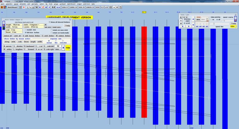 Did I miss something? I know I moved the stock rail joint to toe to compensate for the vertex point, but seing as I started with the S1 timber and corrected for the vertex point. So theoretically it should match up... I think Im to tired, to much work lately and I need some sleep, if someone understands what I missed, please let me know Regards /Leo |
||
| Attachment: attach_1232_1663_Conrail_1979_no8_turnout_for_bolted_119lb_rail-_draft_1.box 213 | |||
|
posted: 7 Nov 2011 22:28 from: Martin Wynne
click the date to link to this post click member name to view archived images |
leo_sandstrom wrote:I finally got around to timbering this turnout, however, I still have discrepancies.Hi Leo, Set that dimension at real > V-crossing options > customize V-crossing > blunt nose... menu item. Set the "width of blunt nose" dimension to 0.5" for most USA V-crossings (frogs). Set the "blunt nose to timber centre" dimension to your 4". I'm tired too. I've been trying to get the next TDV update ready for several days now. regards, Martin. |
||
|
posted: 10 Nov 2011 18:45 from: leo_sandstrom
click the date to link to this post click member name to view archived images |
Hi Martin I already have those dimensions set, I think I might have found a bug, or maybe this feature is just working in a completely different manner then I expect. Setting the blunt nose to timber centre to 0 brings the x spot on the middle of the timber as can be seen here: 2094_101319_200000000.png 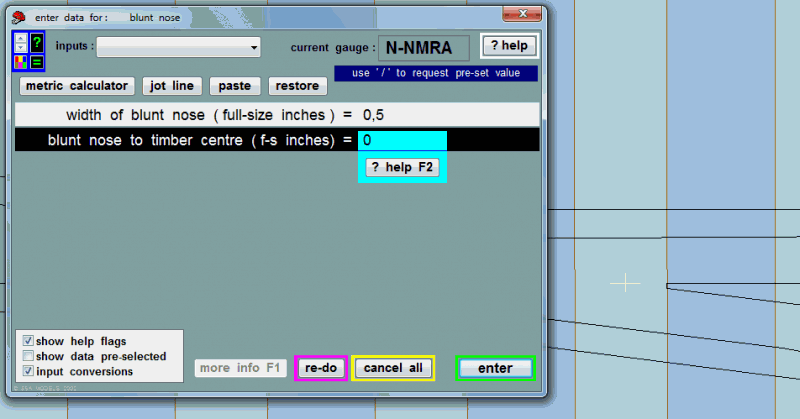 Setting it to 8,96 inches brings it just in line with the left side of the timber as can be seen here: 2094_101333_460000000.png 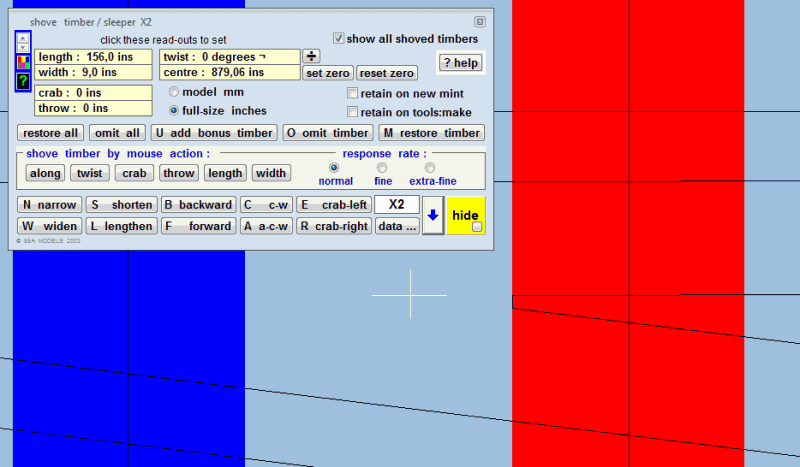 Thus setting it to 8,46 inches puts the blunt nose ½ inch from the start of the timber and 4 inches ahead of the timber centre. Regards /Leo |
||
|
posted: 10 Nov 2011 19:03 from: Martin Wynne
click the date to link to this post click member name to view archived images |
Hi Leo, You have shoved the "A" timber away from its calculated position. Select the "A" timber (numbered Xn-A) and then click the restore timber button on the shove timber dialog. The dimensions for the blunt nose will then work correctly relative to that timber. Generally you should never shove the "A" timber out of position, otherwise the chairs/baseplates/tieplates/fixings for the V-crossing nose will not be correctly positioned on the rails. It is permissible to twist the "A" timber a little to pick up the best positions for the other rails. As I mentioned I will work through this template with you, but I'm sorry I just don't have an evening to spare at present. I was hoping yesterday's TDV update would be the last for a while, but already the need for several maintenance fixes has cropped up. Maybe next week some time. regards, Martin. |
||
|
posted: 10 Nov 2011 19:46 from: leo_sandstrom
click the date to link to this post click member name to view archived images |
After doing the above I realized that the timbers where off... Should have seen that one coming Trying to take a shortcut I adjusted the V Crossing entry straight untill it fits more or less over the old timbers. (that I showed to the correct position and distance from eachother) Now that I think about it, I actually included the distance to the vertex point when I calculated the distance from points to the center of the S1 timber. Thus the 68' lead without adding the distance to the vertex point would be 129,54mm... At the moment the switch has the following lead: actual lead (switch-toe to blunt nose) = 129,53 Yaaay! That means the switch lead of 129,53 is pretty damn close to the exact 68' mark! Then I noticed that the turnout is actually a 1:7,97 (after conversion to CLM) I dont know if this was needed, but I changed it to 1:8 and then shortened the V crossing entry straight so its the correct lenght again. This time I managed to get it to 129,54. I also checked the rail face radius, according to the drawing its to be 443,808', after conversion to model millimeters I end up with 845,45424mm radius according to the calculator. Checking the Templot turnout I got: turnout-curve radius (rail gauge-face) = 845,06 Thats less then 0,4 model millimeters off and should be well within the decimal errors I get for converting to and from the foot system. I have also gone through the timbering again and corrected the small errors incurred. Thus, I hereby declare this turnout completed and to scale. Please let me know if I messed something up so I can correct it! Regards /Leo |
||
| Attachment: attach_1235_1663_Conrail_1979_no8_turnout_for_bolted_119lb_rail_-__with_Micro_Engineering_c40_rail_measurements_v1.0.box 193 | |||
| Last edited on 10 Nov 2011 19:59 by leo_sandstrom |
|||
|
posted: 10 Nov 2011 22:24 from: leo_sandstrom
click the date to link to this post click member name to view archived images |
Martin Wynne wrote:Hi Leo, Hi Martin, didnt see this till now, I think I managed to get everything lined up in the end, despite doing it wrong. Regards /Leo |
||
| Please read this important note about copyright: Unless stated otherwise, all the files submitted to this web site are copyright and the property of the respective contributor. You are welcome to use them for your own personal non-commercial purposes, and in your messages on this web site. If you want to publish any of this material elsewhere or use it commercially, you must first obtain the owner's permission to do so. |