Templot Club Archive 2007-2020
|
|||
| author | remove search highlighting | ||
|---|---|---|---|
|
posted: 30 Jul 2014 11:44 from: Trevor Walling
click the date to link to this post click member name to view archived images |
Hello, I have moved this topic here as I think I had put it in the wrong place previously. I have reached the stage where I need to produce a template or templates for the single slip roads to form a trailing crossover for up and down lines. I have started on the up road slip but I seem to be hitting the buffers so to speak.I followed the tutorial for a single slip but instead of swapping the turnout hand I have inverted it.It sort of works but I seem to end up with extra lines at the switches and confusion. Any help would be most appreciated please as I seem to be at an impasse.I think once I have mastered this first slip I should be able to complete the other.I also enclose the box file.2110_291142_090000000.png  Thanks. Trevor. |
||
| Attachment: attach_1893_2496_upslip_crossover.box 254 | |||
|
posted: 30 Jul 2014 12:10 from: Martin Wynne
click the date to link to this post click member name to view archived images |
Hi Trevor, You moved it while I was preparing a reply! Hi Trevor, You have used standard switches instead of the preset slip switches: 2_300644_220000000.png  Also one of your switches is a 9ft switch, which is unnecessarily short for a 1:7.25 slip. If you use the preset slip switches and peg them on to the TCP and MCP positions, the blade tips will be correctly supported on the timbers and clear of the check rails. (At present you have them in fresh air, and one opening behind the check rail): 2_300700_410000000.png  Also you have long transition zones running through the slip switches, which tends to be unnecessary and confusing. I am not sure what you mean by extra lines? Do you mean the track centres lines for each partial template? They can be turned off in the geometry menu. regards, Martin. |
||
|
posted: 30 Jul 2014 13:59 from: Trevor Walling
click the date to link to this post click member name to view archived images |
Hello Martin, Sorry about moving it while you where doing the reply. I had assumed incorrectly I needed a switch that matched the turnout.(7.25:1)undefined  The transitions are a result of making double track on a curve from a section that contained one and it seemed the easiest way to get the double track parallel. The extra lines I was referring to are these. undefined  undefined  I will have another go making use of your advice.Thanks very much Martin.  |
||
|
posted: 4 Aug 2014 17:52 from: Brian Nicholls
click the date to link to this post click member name to view archived images |
Hi Trevor, I just had a quick look at your single slip issue, and have done a sample which may help, see attached box file. Please be aware, that I have left your original templates as was, and still in the box file, but removed from the background of the trackpad. Also, I may have left some of my test templates in there, but again these have been removed from the background, so can be totally deleted if necessary. The overall roads (rails) of the slip diamond should follow exactly your original box file templates. As you will see, I had to use machined flares for the diamond check rails, and shorten the overall length to fit, but the check rails still perform their task adequately. Similarly for the two diamond Vee check rails on the one side. The slip road switches are both 1:7 B type (or 1:7 slip switches, as Martin suggested). I am sorry I did not spot your posting sooner, but have been too busy doing necessary external DIY on my property, and have not had my PC on for the last couple of weeks. All the best, Brian. |
||
| Attachment: attach_1894_2496_upslip_crossover_BN_Sample.box 288 | |||
|
posted: 4 Aug 2014 22:49 from: Trevor Walling
click the date to link to this post click member name to view archived images |
Hello, Thanks for your input Brian.Like you I have been busy with other things so I haven't had time to try again since Martins reply.I am sure all the information will make it easier for me to complete one myself. Regards. Trevor.  |
||
|
posted: 5 Aug 2014 16:44 from: Trevor Walling
click the date to link to this post click member name to view archived images |
Hello, I have had a go with this slip but I think something is wrong.My slip road seems to be curving incorrectly and appears too close to the sleeper ends.undefined  2110_051123_520000000.png  Is this possibly due to me swapping the hand of the turnout after snapping current template onto background template at TCP? Should I perhaps invert it? 2110_051130_130000000.png  Here's mine. It doesn't seem to align with either route. 2110_051131_190000000.png  The end result I get just doesn't look right 2110_051138_300000000.png  I have followed the slip tutorial so I am guessing at the cause of the result. I hope you can all understand my explanation .I also enclose my box file. Thank you. Trevor. |
||
| Attachment: attach_1895_2496_upslipcrossover2_2014_08_05.box 237 | |||
|
posted: 5 Aug 2014 17:02 from: Brian Nicholls
click the date to link to this post click member name to view archived images |
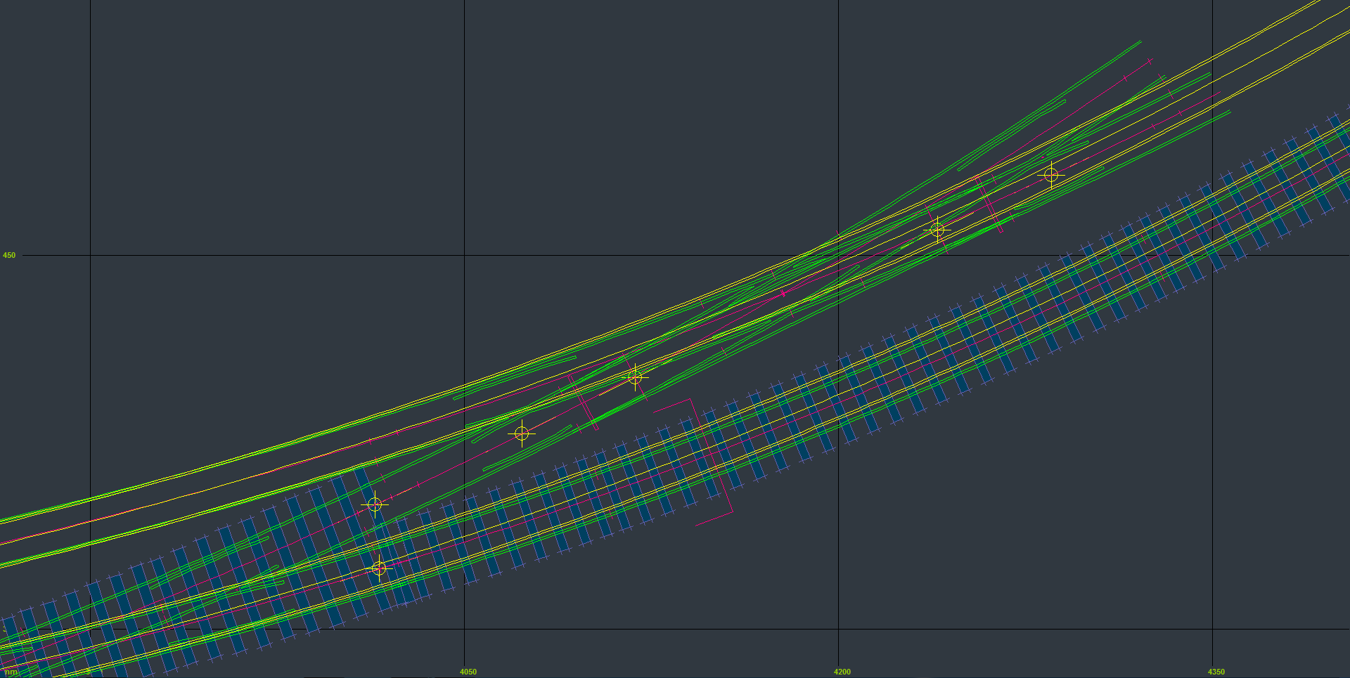
Hi Trevor, I was just about to post this, when your latest message popped up. First let me say, I applaud you determination to do the job yourself, as one learns best by doing things ones self. In addition of course, we also learn by example, hence my input of a sample slip. Now, having again looked at your box file, I am a little concerned that the flow of the inner (where the slip diamond is part of) curving main running line is not aligned properly to give a good flow. This makes the assumption that there are two curved main running lines parallel to each other. If the assumption is correct, then the flow is not quite right. Also I must point out, that I am not aware of your overall layout plan, so can only go on my own assumptions. As an illustration of what I am referring to, see the screenshot PNG images below. In the image, I have arranged the lower yellow main running line to be in position as your original templates in the box file you posted, with the datum of the running line, at the far left-hand side of the main road of the LHS diamond. This track is then adjusted using F6, to align it at the end (the straight line at the back of the arrow head) of the first radius of your transition curved track which goes off to the right, and upwards. I then set the adjacent track centres to give a 7ft way, which is more or less what you originally had. I then made an adjacent parallel track (the upper yellow track) which represents the other main running line with a 7ft way. Please note, that I have used constant radius curves for this illustration as it is quicker and easier to do. Now you will note, that on the left-hand side of the image, the alignment with your original is reasonable good for both upper and lower tracks. However, at the right-hand side of the slip diamond main road exit, the track is converging towards the outer main running line, which would give to the eye, a sort of offset to the flow, if you have parallel adjacent curved main running lines. Now I apologise, if my assumptions are wrong, and you feel I am taking (or commenting) out of place. However, if I may offer you a suggestion, I would first set out the two parallel curved main running lines exactly as you want them to be, without concern for the crossover. Then when you are fully satisfied with those running lines, you can put in the crossover and single slip where you think it should go, without changing or deviating from the curving main running lines.. This should give you a very nice curving flow at the crossover section, which will be much more pleasing to the eye and in fact look correct. I sincerely hope I have not thrown a spanner in the works, but offer the comment in order to improve the flow of your layout and make it look right to the eye. If I can find a little time, I will try and reproduce the crossover and main running lines with the correct flow. However, because I am not familiar with your layout plan, it would help me if you could post more of your layout in a box file, particularly beyond both sides of the crossover. In addition, that part of you layout plan you are working to would be most helpful. All the best, Brian. 1853_051200_000000000.png  1853_051159_110000000.png  |
||
| Attachment: attach_1896_2496_trevors_layout_sample_2_A.png 228 | |||
|
posted: 5 Aug 2014 17:31 from: Brian Nicholls
click the date to link to this post click member name to view archived images |
Hi Trevor, I have just had a look at your latest box file. The first thing I did was to overlay another plain track of constant radius over the lower main running line, the track with just the LHS diamond in the road. Adjusting this track with F6 to fit the overall length, and aligning the ends of the plain track with your existing templates. This plain track of constant radius very, very closely fitted over the existing templates, with only a half rail head width in difference at the centre of the curvature. I would therefore, without hesitation, get rid of your transition curves, as they are not needed, this should then make things much easier to handle, also to quickly and simply add your parallel adjacent main running line. Using your basic box file template positions, I will produce the whole formation again, and you can see what difference there will be in the flow and it should look right. I hope to post this very soon, hopefully later this evening. All the best, Brian. |
||
|
posted: 5 Aug 2014 19:08 from: Brian Nicholls
click the date to link to this post click member name to view archived images |
Hi Trevor, Please find attached the box file of your crossover layout which I have reproduced with NO timbering done. First I must say, I have used all constant radius curves (no transitions). As you will see, this should fit your existing layout OK. Now if you find you need to move any of the slip switches to get them to sit correctly on the timbers, then do the following: 1. put that particular switch to the control. 2. set the peg onto the datum point ( this is most important). 3 using CNTL +F6 (snake through peg) adjust the position of the switch until you have the desired position, then cancel this operation. 4. resave the switch to the background. 5. now put the slip road to the control. 6. adjust using F6 & F4 the curvature and length of the slip road onto the newly positioned switch. 7. recheck and adjust if necessary the shortened check rails of the appropriate half diamond (both the K and Vee crossings if necessary) (these may only need a very slight tweak, or not as the case may be). Job done. All the best, Brian. |
||
| Attachment: attach_1897_2496_upslipcrossover2_BN_Sample_3.box 233 | |||
|
posted: 5 Aug 2014 21:30 from: Trevor Walling
click the date to link to this post click member name to view archived images |
undefined Thank you very much for your input as it all helps.It continues to amaze me just how much of Templot's capabilities remain to be uncovered. the plan I am working from has undergone many changes and compromises to fit the space I have available.The left hand side follows the curved track plan but to the right it goes where I got it to fit.Below are some images of where I started from. 2110_051604_390000000.png  undefined  Below is the current state of play which shows either side where it goes through into the loft. 2110_051620_350000000.png  A bit more detail 2110_051621_490000000.png  2110_051623_010000000.png  I also include a box file |
||
| Attachment: attach_1898_2496_July22.box 286 | |||
|
posted: 5 Aug 2014 21:33 from: Trevor Walling
click the date to link to this post click member name to view archived images |
Hello, I enclose a bgs file for the room as I can't send two together. |
||
| Attachment: attach_1899_2496_Railway_room_loft.bgs 253 | |||
|
posted: 5 Aug 2014 21:37 from: Trevor Walling
click the date to link to this post click member name to view archived images |
Hello again, Here is the bgs of the plan.I hope sending this much stuff is ok Martin. I really feel like I am making real progress using Templot.I don't think it would have been possible to fit this in its location without Templot. I still need to complete the track plan through the loft but that should be simple in comparison. Thank You all. Trevor |
||
| Attachment: attach_1900_2496_LHand.bgs 241 | |||
| Last edited on 5 Aug 2014 21:39 by Trevor Walling |
|||
|
posted: 5 Aug 2014 21:40 from: Martin Wynne
click the date to link to this post click member name to view archived images |
Trevor Walling wrote:Here is the bgs of the plan.I hope sending this much stuff is ok Martin.Hi Trevor, Of course it is ok. That's what Templot Club is here for. Great to see someone using the image wrapping function. regards, Martin. |
||
|
posted: 6 Aug 2014 16:53 from: Brian Nicholls
click the date to link to this post click member name to view archived images |
Hi Trevor, Many thanks for posting all the information, it certainly is a substantial and interesting layout you are working on. Your absolutely right when you say Templot holds amazing facilities, in my opinion, there is none better, and it's all down to Martin's vision and long hard work. Something I did not mention in my last message was, that I have purposely left some guide curves in the box file, which can be used to reproduce the crossover formation, which will give you exactly the same result I produced. You should find these quite easily as they are marked as Upper, Lower and Crossover guide curves. I am looking at your layout (July22) and will get back to you as soon as I can when I have, hopefully, some helpful comments. Just as a matter of interest, I have found a help guide I did way back in 2012 on an alternative method of producing slips, you may find it of some help. Please be aware, it may be slightly out of date, for certain key functions, as compared to the very latest Templot2 edition, but in the main, should be useful. All the best, Brian. |
||
| Attachment: attach_1901_2496_Alternative_Method_of_Constructing_Slips_v1.pdf 222 | |||
|
posted: 6 Aug 2014 18:58 from: Trevor Walling
click the date to link to this post click member name to view archived images |
Hello, Thanks Martin and Brian. I have been experimenting with the slip again and think I have it nearly. Is there a way to move the switch so it is correctly located on the background diamond easily? I have got my mind in a bit of a spin trying to get all the different actions in the right order at the right time. I think it is called getting in a muddle.  Here is an image of its present location. Here is an image of its present location.2110_061355_250000000.png  Thank you. Trevor. |
||
|
posted: 6 Aug 2014 20:34 from: Brian Nicholls
click the date to link to this post click member name to view archived images |
Hi Trevor, Looking at your image of the slip switch, it appears it has shifted off the centre-line of the diamond, and consequently off the alignment with the diamond rails. Regarding the particular slip switch you are showing in the image, it is, if I am not mistaken, situated on the main road of that half diamond. If this is the case, then you can do the following in order to align the switch to the diamond rails, and move the switch to whatever position you like along those rails. First, ensure that the slip switch is a RH (right-hand) switch, check this with the information panel data, then, 1. Put that particular switch to the control. 2. Set the peg onto the datum point of the switch ( this is most important). 3. Right click either the half diamond template or it's label. When the drop down menu appears, select < P peg / alignment tools > < K align the control template over, and snake onto > < T facing - trailing > The slip switch should then move to the centre crossing point of the half diamond, aligned with the centre-line. 4. Repeat instruction No 3 above, this is necessary because when you use the facing - trailing selection, it changes the hand of the switch, and repeating the overall instruction, returns to the correct handing. 5. Now use CNTL +F6 (snake through peg) adjust the position of the switch until you have the desired position, then cancel this operation. 4. Resave the switch to the background. OR, alternately before you save the switch template, 5. Select on the top menu bar < tools > < make slip road > This will create a new slip road from the end of planing of the switch, and save the switch template at the same time. Please Note: The above instructions is to used only for the half diamond main road switch, for the other slip switch which will be situated on the diagonal road, you will need to do the following: You may think this is quite a process, but it does not take long once you are used to it. THIS PART HAS BEEN EDITED OUT !! All the best, Brian. |
||
| Last edited on 6 Aug 2014 20:45 by Brian Nicholls |
|||
|
posted: 6 Aug 2014 20:40 from: Brian Nicholls
click the date to link to this post click member name to view archived images |
Hi Trevor, URGENT !! Apologies, have made an error in my instructions for the diagonal road switch adjustment. The main road instructions are however, correct. I will try and amend the diagonal road instructions as quickly as I can. All the best, Brian. |
||
|
posted: 6 Aug 2014 22:31 from: Brian Nicholls
click the date to link to this post click member name to view archived images |
Hi Trevor, I have re-posted the whole process again for adjusting the slip switches along the diamond rails. Looking at your image of the slip switch, it appears it has shifted off the centre-line of the diamond, and consequently off the alignment with the diamond rails. Regarding the particular slip switch you are showing in the image, it is, if I am not mistaken, situated on the main road of that half diamond. If this is the case, then you can do the following in order to align the switch to the diamond rails, and move the switch to whatever position you like along those rails. First, ensure that the slip switch is a RH (right-hand) switch, check this with the information panel data, then, 1. Put that particular switch to the control. 2. Set the peg onto the datum point of the switch ( this is most important). 3. Right click either the half diamond template or it's label. When the drop down menu appears, select < P peg / alignment tools > < K align the control template over, and snake onto > < T facing - trailing > The slip switch should then move to the centre crossing point of the half diamond, aligned with the centre-line. 4. Repeat instruction No 3 above, this is necessary because when you use the facing - trailing selection, it changes the hand of the switch, and repeating the overall instruction, returns to the correct handing. 5. Now use CNTL +F6 (snake through peg) adjust the position of the switch until you have the desired position, then cancel this operation. 4. Resave the switch to the background. OR, alternately before you save the switch template, 5. Select on the top menu bar < tools > < make slip road > This will create a new slip road from the end of planing of the switch, and save the switch template at the same time. Please Note: The above instructions is to be used only for the half diamond main road switch, for the other slip switch which will be situated on the diagonal road, you will need to do the following: A. Put the other half diamond to the control. B. Ensure the peg is on the datum point, if not put it there. C. Select on the top menu bar < geometry > < peg on line or rail > < on turnout-road centre-line > D. Resave the half diamond template to the background. E. Put that particular switch to the control. F. Set the peg onto the datum point of the switch ( this is most important). G. Right click either the half diamond template or it's label. When the drop down menu appears, select < P peg / alignment tools > < K align the control template over, and snake onto > < T facing - trailing > The slip switch should then move to the centre crossing point of the half diamond, aligned with the diagonal road centre-line. H. Repeat instruction No G above, this is necessary because when you use the facing - trailing selection, it changes the hand of the switch, and repeating the overall instruction, returns to the correct handing. J. Now use CNTL +F6 (snake through peg) adjust the position of the switch until you have the desired position, then cancel this operation. K. Resave the switch to the background. L. Now put the slip road to the control. M. Adjust using F6 & F4 the curvature and length of the slip road onto the newly positioned switch. N. Recheck the clearance, and adjust if necessary the shortened check rails of both half diamonds (both the K and Vee crossings if necessary) (these may only need a very slight tweak, or not as the case may be). Job done. You may think this is quite a process, but it does not take long once you are used to it. This should enable you to put the slip switches where you like along both half diamond rails. All the best, Brian. |
||
| Last edited on 7 Aug 2014 00:03 by Brian Nicholls |
|||
|
posted: 6 Aug 2014 22:38 from: Martin Wynne
click the date to link to this post click member name to view archived images |
Trevor Walling wrote: Is there a way to move the switch so it is correctly located on the background diamond easily?Hi Trevor, If you use the pre-set slip switches there is no need to move them. They are designed to peg onto the MCP and TCP peg positions on the half-diamonds. In the vast majority of cases they will then be in the correct positions. I will make you a bit of video shortly, but I don't have time right now to add any notes to it. regards, Martin. |
||
|
posted: 7 Aug 2014 01:11 from: Martin Wynne
click the date to link to this post click member name to view archived images |
Hi Trevor, Here is your slip attached below. It took me only a couple of minutes to do. Unfortunately to make a smooth-running video of that, write explanations at each stage, and double-check everything, will be a full day's work. I will try to do it tomorrow, but if you need it urgently the file is below. Because it is in 00 it still needs the K-crossing check rail shortening -- over to you to do that. Also, after doing it, sort the half-diamonds back to the top of the box list (lowest numbers) so that the switches overwrite them for a neater result. There is no significant change from the old video and notes, but obviously it is not clear and needs redoing. I wish there was some way I could create the videos more quickly, but after trying a dozen different formats and software over the years I have concluded that there isn't. 2_062008_430000000.png  regards, Martin. |
||
| Attachment: attach_1902_2496_trevor_slip.box 175 | |||
|
posted: 7 Aug 2014 01:19 from: Trevor Walling
click the date to link to this post click member name to view archived images |
Hello Martin, If I use the pre-set slip switches when I peg the first one onto the MCP peg position it doesn't seem to locate on the diamond main road properly. 2110_062014_260000000.png  I think this is where my problem starts with the switch location here. This is following the slip tutorial till pegging onto the MCP position. Thank You. Trevor. |
||
|
posted: 7 Aug 2014 07:00 from: Martin Wynne
click the date to link to this post click member name to view archived images |
Hi Trevor, I can't be sure from your screenshot, but I think you forgot to align the curving direction. After snapping onto MCP, you probably needed to do geometry > invert curving, assuming you started with a turnout copied from the half-diamond on the right. As you are using Crossover/Linux/Wine (is that on a Mac?), can we first establish that you can download and play FBR videos? Download the FBR file below, and then in Templot click the help > video tutorials > new video player menu item on the trackpad. Then on the player click File > Open... and open the downloaded FBR file. (The easiest way to find it may be to download it to an external drive such as a USB memory stick.) Does it play ok on your system? regards, Martin. |
||
| Attachment: attach_1903_2496_basic_buttons_test.fbr 150 | |||
|
posted: 7 Aug 2014 10:22 from: Trevor Walling
click the date to link to this post click member name to view archived images |
Hello Martin, I am using Linux/Wine on a PC and the FBR video downloaded and played fine.I will try the geometry > invert curving step as suggested. You must have replied while I was compiling my last post in the early hours and at the crack of dawn as well. Thank you very much for your assistance which as usual is beyond what one would expect from anyone. It seems you never sleep. Best regards. Trevor |
||
|
posted: 7 Aug 2014 12:39 from: Trevor Walling
click the date to link to this post click member name to view archived images |
Hello, Here is my latest attempt. I have used the geometry > invert curving step on the switch I was having trouble with and I think it worked. I encountered a similar issue with the opposite one as well. I think I sorted that as well. 2110_070734_300000000.png  undefined I will upload the pdf of the printout next |
||
| Attachment: attach_1904_2496_upslip_crossover.box 169 | |||
|
posted: 7 Aug 2014 12:45 from: Trevor Walling
click the date to link to this post click member name to view archived images |
Hello, Here is the pdf. I would appreciate if any errors or omissions could be pointed out please. The inverting and swapping hands in the process used is easy to mess up. I don't think that can be helped till one uses Templot doing the same procedures a few times. Thank You. Trevor. |
||
| Attachment: attach_1905_2496_upslipcrossover.pdf 220 | |||
|
posted: 7 Aug 2014 13:52 from: Martin Wynne
click the date to link to this post click member name to view archived images |
That looks good Trevor. For overscale flangeways in 00 you need to change to half-diamond timbering as model so that the tips of the diamond point rails are properly supported on a timber. This avoids having to do timber shoving afterwards. regards, Martin. |
||
|
posted: 8 Aug 2014 21:12 from: Trevor Walling
click the date to link to this post click member name to view archived images |
Hello, Here is the up-down-slip-crossover that I have been working on. Any comments would be most welcome before I try to integrate it into my overall plan.undefined  Below is the box file and I will put the pdf in next post Thanks. Trevor. |
||
| Attachment: attach_1907_2496_up-down_slip_crossover2.box 178 | |||
|
posted: 8 Aug 2014 21:18 from: Trevor Walling
click the date to link to this post click member name to view archived images |
Hello again, I have attached the pdf for anyone interested. I am really enjoying getting to grips with Templot. Unlike all those video games some people spend ages playing Templot gives you something which is very satisfying, constructive, and educational. Regards. Trevor. |
||
| Attachment: attach_1908_2496_up-down-slip-crossover2_2014_08_08_2101_37.pdf 184 | |||
|
posted: 8 Aug 2014 23:52 from: Martin Wynne
click the date to link to this post click member name to view archived images |
Hi Trevor, That's looking good. When you have finished working on the half-diamonds, use the brown buttons on the storage box to move them to the top of the list, or at least above the corresponding slip switches: 2_081740_420000000.png  That way the slip switches will overwrite them in the output for a neater result, with the rail edges properly shown for the switch blades and the set in the stock rail matching the marker. This is a quick fix, to avoid the need otherwise to split out the rails from the underlying template as partial templates. If you select all the slip half-diamonds as a group, you can move them to the top all in one go by clicking the box > sort group templates menu item on the storage box. If you make any subsequent changes to a half-diamond, such as further timber shoving, don't forget to repeat this process. regards, Martin. |
||
|
posted: 18 Aug 2014 18:04 from: Martin Wynne
click the date to link to this post click member name to view archived images |
Hi Trevor, I said I would make a new single-slip video. It is now online, see: topic 2511 regards, Martin. |
||
|
posted: 18 Aug 2014 22:37 from: Trevor Walling
click the date to link to this post click member name to view archived images |
Hello Martin, That is the bee's knee's. It fills all the blanks in and I have many of those.Thank you. Trevor.  |
||


| Please read this important note about copyright: Unless stated otherwise, all the files submitted to this web site are copyright and the property of the respective contributor. You are welcome to use them for your own personal non-commercial purposes, and in your messages on this web site. If you want to publish any of this material elsewhere or use it commercially, you must first obtain the owner's permission to do so. |