Templot Club Archive 2007-2020
|
|||
| author | remove search highlighting | ||
|---|---|---|---|
|
posted: 2 Oct 2009 17:16 from: Jamie92208 click the date to link to this post click member name to view archived images |
the attached box is my design for a new O gauge exhibition layout to replace my current one based on Long Preston near Settle. It will be built with overhead for the early Midland Electrics thought the overhead will not be working as it would be too much trouble to wire p the fiddle yard. This is my first attempt at a templot design and any comments would be appreciated. I'm not sure how to uplad the background shapes that show the base board outlines as well as the track plan. Jamie Guest |
||
| Attachment: attach_660_948_green_ayre_09_09_20_1752_08.bgs 595 | |||
|
posted: 2 Oct 2009 22:30 from: Jamie92208 click the date to link to this post click member name to view archived images |
For those of you who have looked at this the layout had several design constraints, the main one of which was that it had to be the same overall size as Long Preston. 5cms longer and it won't go into my church when it gets put up for testing. The curved river bridge had to lead into the fiddle yard and that meant that I couldn't have it viewed from the river side which would have looked nice visually. There have been several changes to the geometry but the overall layout with the branch to Lancaster Castle and the shed have been kept. The station is almost exactly the correct size with a main building over 5' long. The hatched area is the shed but I haven't had time to put it in its correct alignment. | ||
| Last edited on 3 Oct 2009 06:46 by Jamie92208 |
|||
|
posted: 3 Oct 2009 12:42 from: Nigel Brown click the date to link to this post click member name to view archived images |
Jamie Unless I've missed something, I can only see a bgs file attached, not a box. cheers Nigel |
||
| Last edited on 3 Oct 2009 12:43 by Nigel Brown |
|||
|
posted: 3 Oct 2009 20:35 from: Jamie92208 click the date to link to this post click member name to view archived images |
Thanks for that Nigel. My mistake as I am new to this. The box file should be attached to this message. Jamie |
||
| Attachment: attach_661_948_green_ayre_09_10_02_1729_03.box 473 | |||
|
posted: 4 Oct 2009 08:10 from: Jim Guthrie
click the date to link to this post click member name to view archived images |
Jamie92208 wrote: the attached box is my design for a new O gauge exhibition layout to replace my current one based on Long Preston near Settle. It will be built with overhead for the early Midland Electrics thought the overhead will not be working as it would be too much trouble to wire p the fiddle yard. This is my first attempt at a templot design and any comments would be appreciated. I'm not sure how to uplad the background shapes that show the base board outlines as well as the track plan.Jamie, Only that there seems to be a wee dog leg in "41 No name". I would be tempted to move the turnout/diamond on the main line a bit to the right so that you might get a smooth curve leading to the turnout in the goods yard getting rid of the need for an "S" curve in the "41 No name" area. Jim. |
||
|
posted: 4 Oct 2009 08:56 from: Jamie92208 click the date to link to this post click member name to view archived images |
Jim Guthrie wrote: Jamie92208 wrote:the attached box is my design for a new O gauge exhibition layout to replace my current one based on Long Preston near Settle. It will be built with overhead for the early Midland Electrics thought the overhead will not be working as it would be too much trouble to wire p the fiddle yard. This is my first attempt at a templot design and any comments would be appreciated. I'm not sure how to uplad the background shapes that show the base board outlines as well as the track plan.Jamie, Thanks for the help Jim. I had rejogged that area to try and get all the coal yard points on the front row of basebaords and not have an awkward joint in the middle of a turnout. One of my constraints is to keep all the overhead on the inner row of boards to save space on crating and storage. I've now followed your suggestion and redone that area. Moving the main line point along also helps scenically as there are several alterations to geometry in that area to make the layout fit to exhibit and get the curve round to the fiddle yard. In reality the main line in that area is nearly straight. I the scenic break which will be an overbridge has been turned around by about 70 degress from the real thing and moved along a bit. Moving the point helps keep the interest in that area. Thanks again for the advice. I've attached the new box file and will pot another reply with the real trackplan on it. Jamie |
||
| Attachment: attach_662_948_green_ayre_09_10_04_0855_17.box 421 | |||
|
posted: 4 Oct 2009 09:28 from: Jamie92208 click the date to link to this post click member name to view archived images |
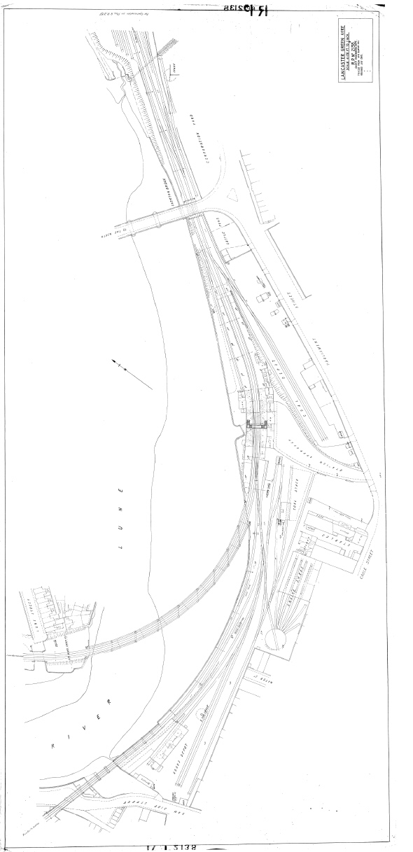
As promised above I have now managed to resize a scan of the 1:500 rating plan and it is attached. Jamie |
||
| Attachment: attach_663_948_green_ayre_map_3.jpg 2216 | |||
|
posted: 8 Dec 2009 12:19 from: Jamie92208 click the date to link to this post click member name to view archived images |
CAN ANYONE HELP PLEASE I'm now actually starting to cut timber and have also just found a tresure trove of original drawings of all the overhead equipment. I now realise that I need to move my main platform line so that the edges are at least 3" from the board edge so that the overhead gantries are supported on the same board. These are the right of center long boards (B5 and B6), particularly B5. Is there any way that I can flatten out the curve (which would fit in with the protoype without having to start from scratch and alter all the pointwork at both ends. It is only the plain lines through the platforms that are the problem. If the pontwork at the right hand end of the layout (The East end of the station, has to move a bit that is no problem., likewise the inner edge of the platforms can come closer to the edge of the boards. I still want to try and keep the transition curve. I've attached the latest box and background files. Thanks in advance Jamie |
||
| Attachment: attach_698_948_green_ayre_09_12_06_0926_04.box 384 | |||
|
posted: 8 Dec 2009 12:20 from: Jamie92208 click the date to link to this post click member name to view archived images |
Here is the latest bgs file I can't seem to add both to the same reply. Jamie |
||
| Attachment: attach_699_948_green_ayre_09_12_06_0925_58.bgs 402 | |||
|
posted: 8 Dec 2009 21:57 from: Jamie92208 click the date to link to this post click member name to view archived images |
Jamie92208 wrote: CAN ANYONE HELP PLEASE I've now had a go and think that I've cracked it it may not be very elegant and up to Martin's standards but it looks OK to my eyes. the latest .box file is attached. The reason I've had to sort this out is that I've just managd to obtain a set of the original contract drawings for the Overhead line equipment dated 1907. These show every structure on the route in great detail including many details of the station and awning as well as all the steelwork. I realised that the masts are going to have to be very well fixed to the boards and realised that that area was a bit tight. Sorry if I've wasted anyone's time anyone about. Jamie |
||
| Attachment: attach_700_948_green_ayre_09_12_08_2151_55.box 379 | |||
|
posted: 8 Dec 2009 22:58 from: Jim Guthrie
click the date to link to this post click member name to view archived images |
Jamie92208 wroteI've now had a go and think that I've cracked it it may not be very elegant and up to Martin's standards but it looks OK to my eyes. the latest .box file is attached.Jamie, That looks fine. There's a bit of extraneous track in and around "88.UM Connector" but I suspect a quick bit of work with F4 will sort that out,  I might come chasing you for some of your Midland OHL details. I've had a hankering to build a set and having the proper OHL would be good. The original actually looked very modern for a turn of the century installation. Jim. |
||
|
posted: 9 Dec 2009 07:27 from: Jamie92208 click the date to link to this post click member name to view archived images |
Thanks for that Jim. I;ve made the necessary amendments and things look OK. I'm now working ona paper prototype for the palform awnings. Jamie |
||
|
posted: 19 Feb 2010 23:35 from: Jamie92208 click the date to link to this post click member name to view archived images |
Well some real progress in the last 2 weeks. First of all a start was made on the bseboards and the first three are looking well. 33_191825_060000000.jpg The one nearest the camera is the king boards that the bridge will be attached to, the end plate for that boards is cramped to it. Now I'm putting another layer of 3mm ply where the tracks will go, then a layer of cork will be added followed by the templot printout for track construction. To get the 3mm ply cut to shape I put the oieces on the board , mark a rudimentrary grid at 200 mm intervals on the x axis then transfer the y coordinates from Templot, then cut it out with a tenon saw. It works well. teh second bit of prgress is that I've now got acces to the original drawings of Greyhound bridge which is one of the layout centrepieces. It now carries the northbound A6 and network rail wouldn't even tell me if they had any drawings of it. I finally got them from the bridge engineer for lancashire County Council who has been wonderfully helpful. I've ow had them photocopied to 7mm scale so that the main girders and piers can be produced. I've even got a cross section tat shows the curved overhead gantries, which were mssing form the other set of drawings. here is a pdf of the cross section. |
||
| Attachment: attach_739_948_greyhound_portal.pdf 399 | |||
|
posted: 1 Mar 2010 08:51 from: Jamie92208 click the date to link to this post click member name to view archived images |
HELP PLEASE I am now progressing well with the first set of baseboards and hopefully will start laying track in April when I can move the boards to the clubrooms. In the meantime I am trying to tidy up the rest of the trackplan. I am having trouble with the right hand end of the layout as you look at the plan. I have inserted a trailing crossover on the curve and this will be used a lot during shows as a constant shuttle of EMU's will use it to reverse, twice in every cycle. There are however two constraints and I am having trouble meeting these. 1. The layout has been designed at 90mm track centres but the fiddle yard (Which is from my old layout ) is built at 83mm. This means that on the curves at the ends the track centre's need to converge to match the fiddle yard. 2. The crossover needs to fit on the irregular shaped board that it is mainly on. The point motors need to be mounted so that they clear the end plates of the board (22mm softwood). I am struggling to get a layout that has both point tie bars on the board. I want to try to keep to a minimum 6' radius and accept that the down main (Outer track) will have a switched frog. I have tried to use the command 'create simple crossover TS'. This creates another nice Xover with a 1:22.5 point which is far to long on the inner track. If I then shrink the point with F5 the curvature goes haywire and I can't get it to match up. Can anyone help. idealy the tie bars need to be about 50mm from the end of the board. Jamie Guest |
||
| Attachment: attach_742_948_green_ayre_10_02_28_1445_33.bgs 379 | |||
| Last edited on 1 Mar 2010 08:53 by Jamie92208 |
|||
|
posted: 2 Mar 2010 10:29 from: Jamie92208 click the date to link to this post click member name to view archived images |
Jamie92208 wrote: HELP PLEASE Sorry the box file didn't attach. Should be here. |
||
| Attachment: attach_743_948_green_ayre_10_02_28_1858_35.box 379 | |||
|
posted: 2 Mar 2010 10:41 from: Martin Wynne
click the date to link to this post click member name to view archived images |
Hi Jamie, I've managed to fit a D-12 / C-12 crossover in that board. See below. By changing to generic V-crossings the minimum radius on the crossover road is 68.5" -- not quite the 72" you are looking for, but with a bit of gauge-widening it would probably be ok. For curved crossovers you can usually go down one switch size on the inner turnout. If you want a much longer crossover you could move the inner switch to the next board and put the board joint through the turnout. 2_020531_380000000.png  Impressive looking layout for 0 gauge.  p.s. I don't understand your comment about a switched frog? regards, Martin. |
||
|
posted: 2 Mar 2010 12:14 from: Jamie92208 click the date to link to this post click member name to view archived images |
Thanks for that very helpful reply Martin. That looks fine. As most of the crossing moves will be by 3 car emu's the marginally reduced radius should be fine. I didn't want it to go onto the next board as the scenic break is at that joint. The crossover is to help make more interest in an area where I can't put too much scenery. In reality it was the start of sidings both sides of the line with points and headshunts. I might even put the headshunt's in as disconnected tracks and put some batterred old piece of stock on them. The corssover was in that area and was used in this fashion intil 1933 when the single slip was converted to a double slip at the other end of the station and the platforms were signalled for reversible working. The switched frogs come from experience with my existing Long Preston Layout where I found that with long curved points (above 1:10) that switched frogs made the running very much more reliable and the wheels didn't drop into the flangeways. There are three of them on each of the fiddle yard approaches to provide access to what was meant to be an engine release road that runs via a turntable in the centre of the fiddle yard. It hasn't got used very much during exhibitions but is very useful in the last hour as trains can be run off up the two inclines and packed away without interfereing with the other trains that are still running. It helps us get out of the hall and back home in a reasonable time. I just haven't bothered to try and plot them on this file as they are already built and working. A friend of mine designed them for me on Templot and that was what made me buy a copy for myself as I as so impressed. The road will be retained but I am losing the turntable board and most of another one to get a shorted fiddle yard. This helps me keep the overall size the same as Long Preston and more importantly means that the completed layout will still fit in my church for testing. There is 1.5" to spare between a pillar at one end and a radiator at the other. Jamie PS Is it possible to send me the updated box file |
||
| Last edited on 2 Mar 2010 12:17 by Jamie92208 |
|||
|
posted: 2 Mar 2010 13:03 from: Martin Wynne
click the date to link to this post click member name to view archived images |
Jamie92208 wrote: The switched frogs come from experience with my existing Long Preston Layout where I found that with long curved points (above 1:10) that switched frogs made the running very much more reliable and the wheels didn't drop into the flangeways.Hi Jamie, It's impossible for a wheel to drop into flangeways, no matter how flat the crossing, if you are using the correct wheel-width for the track standard. Unfortunately many 0 gauge wheels are too narrow for the G0G-F standard they are intended for. Hence the wheel drop problem. Have you looked at 0-MF (31.5mm gauge, 1.5mm flangeways)? It's really a much better option than G0G-F and easily accepts all current wheels*, which will run fully supported through the crossings. It looks better too. A swing-nose crossing in bullhead is a very rare thing and will look odd on a visible scenic section. For some track pics of a large layout using 0-MF, see: http://www.rmweb.co.uk/community/index.php/blog/253/entry-1422-heyside-trackwork/ Richard is a member of this parish, see: topic 911 - message 5256 I'm sure he would be happy to comment on his experience of 0-MF if you contact him here or via RMweb. *except S7 of course. PS Is it possible to send me the updated box file?Sure, I will post it shortly -- needs fine tuning to match your transitions. regards, Martin. |
||
|
posted: 10 Apr 2010 23:02 from: Jamie92208 click the date to link to this post click member name to view archived images |
Progress at last. the first 3 baseboards are up in the clubrooms and work has comnmenced. I've got boards B3, B4 and C3 up so far which are the station area , Greyhound bridge and the single slip that is the key to the whole layout. The composite ply construction has worked well with 6mm baseboard surface and an extra layer of 3mm where the track goes. This is plotted on using the x and y coordinates fromn Templot , every 200mm, then cut glued and pinned on. Then a layer of 1/8" cork (1 foot squares from Wickes) then finally the Templot printouts on 160gm paper. Last night we got the paper down on the bridge board (Where I'm having to start the track laying) and then finally laid one rail in individual C & L components using MEK (bought in bulk for economy). It's great to actually have a length of rail down at last. The next job is to put some brass screws through near the end and solder the rail to them to act as droppers, that's after I've put the check rails and inner running rail on. At home while looking after my wife whose just had a knee replacement I've got on with building more baseboards and now have another 4 in the garage ready to take to the club as space becomes available, The pile of timber is reducing slowly. Hopefully the first test vehicles can run on the bridge soon and we can test the clearances with 60' stock so that we can decide how wide to build the bridge. Due to the tighter than prototype curve the bridge has to be wider than the real one to allow for overhang etc. The great thing last night was that when we finished pasting down umpteen A4 sheets of paper they matched the far edge of a long baseboard to within 1mm that's a real tribute to Templot. The station buildings were also brought in last night and looked great. They are now in 4 sections and will be over 6' long. I've got to get on with designing the awning. Hope this is all of interest. I'm looking forward to getting the box files for the crossover that Martin designed for when we get to board C4. I've just made the one that leads onto it today. Jamie |
||
|
posted: 17 Apr 2010 08:31 from: Jamie92208 click the date to link to this post click member name to view archived images |
Hi Martin I've re read your message about the crossover at the east end of the layout and had a play along the lines that you suggested. The latest .box file is attached. The minimum radius is 69.9" which should be fine as it will be almost all bogie emu's that use this Xover. I'll attach the lastest bgs to the next message. Any comments/suggestions would be much appreciated. Thanks for your patience Jamie |
||
| Attachment: attach_777_948_green_ayre_10_04_17_0826_22.box 315 | |||
|
posted: 17 Apr 2010 08:32 from: Jamie92208 click the date to link to this post click member name to view archived images |
Hi again here is the .bgs file Jamie |
||
| Attachment: attach_778_948_green_ayre_10_04_13_1953_36.bgs 272 | |||
|
posted: 22 Apr 2010 17:23 from: Martin Wynne
click the date to link to this post click member name to view archived images |
Hi Jamie, You mixed a 1:10 crossing with a 1:12 crossing in your crossover. Normally for a crossover both turnouts have the same crossing angle.The crossover here is a D-12 + C-12. Minimum radius is 1747mm (68.8"). The track centres increase from 83mm to 90mm in the top-right 90-degree turn. I reworked some of your other templates to repair some misalignments, normalise transitions, etc. The turnout leading to the bay platform was excessively sharp (curved B-6), I've replaced it with a B-8. No timber shoving done -- over to you.  File attached. Add as a group to compare with your originals. 2_221220_560000000.png  regards, Martin. |
||
| Attachment: attach_784_948_green_ayre_mods_for_jamie.box 253 | |||
|
posted: 22 Apr 2010 18:58 from: Jamie92208 click the date to link to this post click member name to view archived images |
Hi Martin Thanks very much for the hard work and the reply. It looks great. I've done what you suggested and merged the two sets of templates and they look fine. I'm glad you suggested re working the bay platform lead that should make reversing trains into there a lot easier. As far a I can tell this was used for portion working as far as Wennington so ECS would come from Morecambe then reverse into the bay before setting off to Wennington to be combined with the portion from Barrow and Carnforth. I believe that the occaisional spare electric unit was stabled there. I will look forward to building this complex in a month or two. I've started at the other end of the station and now have the first yard of double track on the viaduct area complete with check rails. Hopefully in about 5 years you should be able to see the results of our efforts. Thanks again. Jamie |
||
|
posted: 25 Apr 2010 21:32 from: Jamie92208 click the date to link to this post click member name to view archived images |
At last some real progress. A double curve with both tracks fitted with checkrails, laid and two locos actually run under power to test and check clearances.33_251630_040000000.jpg This shows how we have laid the check rails section. 2 chairs, miss one on the running rail and 1 chair miss 2 on the check rail. The intention is to try and chemically colour the checkrail so that the colour isn't rubbed off when we clean the track. The Compound was to check the overhang for positiong the bridge girders and the Kirtley to see how a stiff 0-6-0 coped with the 6' radius curve and checkrails. Both worked well. |
||
| Last edited on 30 Aug 2010 12:10 by Jamie92208 |
|||
|
posted: 22 Jun 2010 17:07 from: Jamie92208 click the date to link to this post click member name to view archived images |
Adding Overhead This might be worth a topic on it's own but I've now got to the point where I need to plan the overhead line equipment in detail. Even though I've got the original engineering drawings for it all it is complicated by the fact that the geometry of several parts of the layout has had to be altered to make the layout buildable, testable and exhibitable. In particualr certain areas have either had to be stretched or compressed to sort out baseboard joints. Also the curves are about half the true radius. This means that I have to space my OHLE gantries closer together on curves to keep the lines in registration above the track. I was intending to do all this on paper but have discoverd a rough an ready method of planning the wiring and keeping within the tracking abilities of a 27m wide pantogrph or bow collector. The attached Box and BGS files show my first atttempts at this over the pointwork either side of the station. I have used shoved timbers to show the positions of the gantries and then used mousedrawn lines in background shapes to show the contact wire trace. This enables me to make sure it is never nearer than 2.5mm to a rail. This method seems to do what I want it to do but comments would be welcome. The BGS will be attached to the next reply. Jamie |
||
| Attachment: attach_808_948_green_ayre_10_06_22_1658_31.box 230 | |||
| Last edited on 30 Aug 2010 12:09 by Jamie92208 |
|||
|
posted: 22 Jun 2010 17:08 from: Jamie92208 click the date to link to this post click member name to view archived images |
Here's the BGS file with the OLE on the inner main at either end of the station. Jamie |
||
| Attachment: attach_809_948_green_ayre_10_06_22_1658_26.bgs 259 | |||
|
posted: 22 Jun 2010 18:19 from: Martin Wynne
click the date to link to this post click member name to view archived images |
Hi Jamie, That's very interesting. Note that you don't need to shove one of the existing timbers to create a gantry, you can add a bonus timber for the purpose. You may also be interested in this message from the archive: http://groups.yahoo.com/group/templot/message/2270 I've attached that .box file below, for those without access to the Yahoo group files. I also updated it to 091c and shortened it a bit. Note that it is a library template without any rails, so you need to follow the instructions in that message and ignore the invitation to delete it. regards, Martin. |
||
| Attachment: attach_810_948_ole_masts_at_240ft.box 266 | |||
|
posted: 22 Jun 2010 18:59 from: Alan McMillan
click the date to link to this post click member name to view archived images |
Hi I've built OHLE on a couple of layouts now and am planning more on a third. I've developed the following method for placing the masts and setting out the wiring pattern. I push ordinary dressmakers pins into the track between the rails at all the important places (toe ends of turnouts, ends of sidings etc) and then string white thread between them, placing further pins at the appropriate points on the layout to signify mast positions between those earlier fixed positions. The pins and thread can be adjusted to give the correct amount of contact wire stagger at each mast position and span midpoints. The threads at mast and portal positions can then be used to create drawn templates for the construction of the wiring supports. Alan McMillan |
||
|
posted: 23 Jun 2010 08:10 from: Jamie92208 click the date to link to this post click member name to view archived images |
Thanks for those replies Martin and Alan. I'd forgotten about bonus timbers but will use them. Fortunately my OLE is all portal's so I can use long timbers that show up easily. The mouse lines give me a fairly good idea of where I am going but the cotton idea is good and I will certainly use that. I need to keep the wire within a 27mm stagger otherwise I will have dewirements. The difficult area is the east end of the layout where the bay platform line joins the up main opposite the lead to the coal yard. In reality this was straight so the portals were well spaced out. Due to the curve that I have had to put in I need to have fairly closely spaced portals and it seems to work out that I need one that spans 4 tracks (The bay headshunt, up and down mains and coal yard headshunt). The Midland would have used a long lattice gantry for this but there was only one of those at the west end. In this area it was all wooden poles connected by back to back L girders or channels. What I might do is see if I can move the headshunts outwards very slightly to give enough clarance to put a standard wooden pole portal in. On another note entirely can I thank Martin for the ProgeCAD suggestion that you made on RMWeb. I have struggled to get my head round CAD for years but have now managed to make a start thanks to a series of tutorials on You Tube. I have now managed to get some inital artwork for OLE parts produced. It needs some tweaking but I am getting there. The attached pdf shows my efforts to date with the warren trusses for the awnings and some OLE parts. Jamie |
||
| Attachment: attach_811_948_GA_Overhead_2.PDF 407 | |||
| Last edited on 23 Jun 2010 08:16 by Jamie92208 |
|||
|
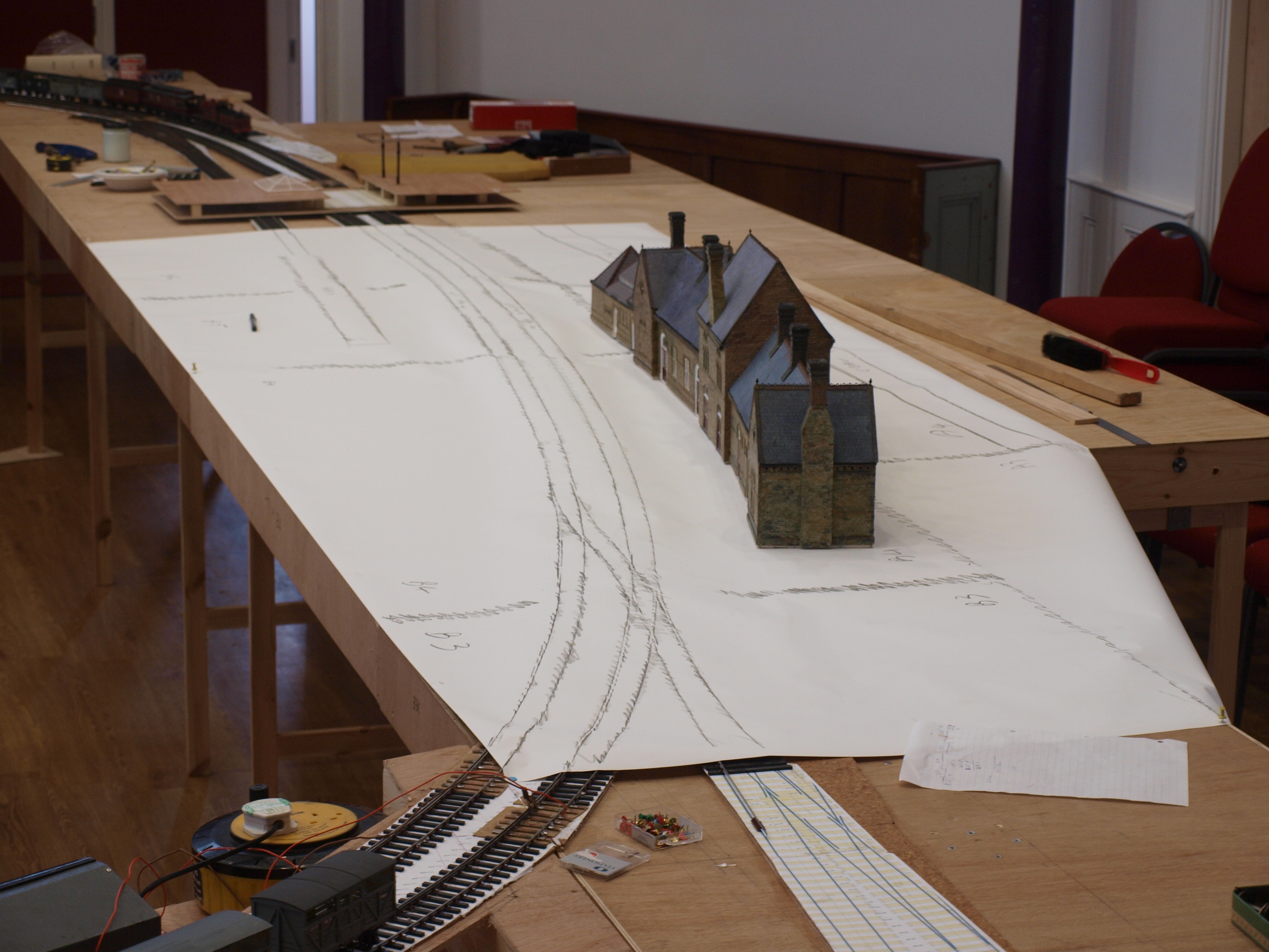
posted: 29 Aug 2010 14:25 from: Jamie92208 click the date to link to this post click member name to view archived images |
Just a quick update. A lot of work has been going on and I have just had the use of my church for 3 days to put all the baseboards that exist up. We got the front of the main line circuit up and everyone commented on the lovely sweeping curve through the station.. 33_290903_510000000.jpg  The next difficult bit is to accurately locate the buildings and platforms. After a bit of head scratching we found a roll of label stock paper over 4' wide. Part of this was unrolled over the station site and then rubbed over with wax crayon to produce a 'brass rubbing'. Then the station building was put on and measured so that the awnings could be properly located. The awnings are going to be fixed to the board. The building footprint was marked and then we spent time plotting in such things as the platforms, overhead gantries and the station approach road, as well as the baseboard joints. I now need to check my clearnaces and mark the platform edges. The plan is to then cut up the brass rubbing and peel the backing off and stick it down onto 3mm ply which will become the platforms/road surfaces etc. This will be supported on noggins cut from 1" square timber at 6" to 8" centres. The prototype for the platform and awnings is in the background. 33_290915_410000000.jpg  After that we couldn't resist the opportunity to play trains and take a few videos of trains running past the station and onto Greyhound Bridge. 33_290920_270000000.jpg  The opportunity was also taken to put the Long Preston Fiddle Yard in place to try it out. The unanimous decision of the jury that was present was that it looked tired and wasn't up to the standard of the new boards. Also a lot of alteration are going to have to be made to the track layout to cope with the various traffics that are in the working timetable. This has meant a lot of midnight oil being burnt on Templot ovr the last 2 days to work out the layout of a new fiddle yard. I will upload a new box file in due course for comment. |
||
| Attachment: attach_850_948_P8276429.JPG 295 | |||
| Last edited on 30 Aug 2010 12:12 by Jamie92208 |
|||
|
posted: 30 Aug 2010 07:06 from: Jamie92208 click the date to link to this post click member name to view archived images |
I have now had time to come up with a new fiddle yard design. The attached box file is a rough version of what I am trying to achieve. It is driven by several factors. 1. The length of the fiddle yard has had to be reduced to keep the overall dimensions of the layout small enough to fit in my church for testing. 2. I have tried to eliminate curved basebaords and the remainder are a standard 5' long. 3. The pattern of working is dictated by the working timetable and this has two main quirks. a) There are a large number of light engine movements from the shed that go into the station then reverse and set off towrds Morecambe and Heysham coupled with balancing working off terminating westbound trains. b) there are four different sets of short trip workings that oiginated in sidings that would have been on the inside of the layout between the main line and the river at the east end of the station. To accommodate 3(a) I have created a centre road in the fiddle yard with a loop at the far end. This road is for two workings: i) for the emu's to reverse ii) for the light engines to go and the loop at the end is for a shuttle unit where some 5 light engines will be stored for 3(b) there is a sharply curved line that leads to a cassette that saves the trip workings having to cross the main lines. With conventional ladders I was short of spce in the fiddle yard so have tried to lengthen the sidings as much as possible. The outer Up Yard is reasonable but the down yard became very cramped as I can't decrease the curvature. Any comments and suggestions as to how this layout could be improved would be welcomed. The .box file is attached the bgs file will be on the next reply. Jamie |
||
| Attachment: attach_851_948_green_ayre_10_08_30_0654_26.box 259 | |||
| Last edited on 2 Sep 2010 22:08 by Jamie92208 |
|||
|
posted: 30 Aug 2010 07:08 from: Jamie92208 click the date to link to this post click member name to view archived images |
Here is the background shape file as promised. Jamie |
||
| Attachment: attach_852_948_green_ayre_10_08_28_1816_26.bgs 285 | |||
|
posted: 26 Oct 2010 16:57 from: Jamie92208 click the date to link to this post click member name to view archived images |
Not a lot of progress to report over the last 2 months but we have been busy. The coal yard sidings are nearly finished including the double slip. The next boards will be the ones that have the start of the Castle branch and the goods yard at the other end of the layout. These will be followed by the ones that the shed is on. One decision has been made however which is to operate the signals with servos using the control board supplied by MERG. I have modified the signals on Long Preston so that we can test them out on it's last outing at Wakefield in November. They seem to work well and MERG membership is well worth it. I'll post some pictures of completed boards in due course. Jamie |
||
| Last edited on 26 Oct 2010 16:58 by Jamie92208 |
|||
|
posted: 16 Jan 2011 19:11 from: Jamie92208 click the date to link to this post click member name to view archived images |
After 2 months spent running an exhibition, looking after a wife who has had a knee replacement and dismantling my old Long Preston layout I have finally started work again on Green Ayre. The next board was taken to the club on Friday and we started laying the 3mm ply for the trackbed. Then the cork goes on then we can start tracklaying again. I am getting to the point where I will have to install my turntable that i have been building, and it's approach tracks. These involve a crossing at about 40 degrees. This is too acute for using the half diamond option so I have just overlaid the tracks. Can anyone point me in the direction of how a crossing like this would be timbered as we will be getting to that point in a week or two. I have attached the latest box file. Thanks in advance Jamie |
||
| Attachment: attach_967_948_green_ayre_10_12_17_1630_16.box 253 | |||
|
posted: 16 Jan 2011 22:06 from: Jamie92208 click the date to link to this post click member name to view archived images |
Please ignore the above request. I've just used the search facility and discovered that I asked this question over 3 years ago and got a very helpful reply from Martin. Unfortunately I;ve slept since then and obvioulsy had a senior moment. Jamie |
||


| Please read this important note about copyright: Unless stated otherwise, all the files submitted to this web site are copyright and the property of the respective contributor. You are welcome to use them for your own personal non-commercial purposes, and in your messages on this web site. If you want to publish any of this material elsewhere or use it commercially, you must first obtain the owner's permission to do so. |