Templot Club Archive 2007-2020
|
|||
| author | remove search highlighting | ||
|---|---|---|---|
|
posted: 5 Apr 2008 22:08 from: Stewart McSporran click the date to link to this post click member name to view archived images |
I've written up some notes on how I create interlaced sleeper turnouts with Templot and posted them on my website. So, if you're interested you'll find them at http://grotsoft.net/Railways/Templot/InterlacedSleeperTurnouts.aspx cheers Stewart |
||
|
posted: 7 Apr 2008 18:32 from: Martin Wynne
click the date to link to this post click member name to view archived images |
Stewart McSporran wrote: I've written up some notes on how I create interlaced sleeper turnouts with Templot and posted them on my website.Hi Stewart, Excellent. Many thanks for taking the trouble to do that. But please note that Templot has a function to put the timber ends in line, you don't need to do it manually: ends_in_line.png 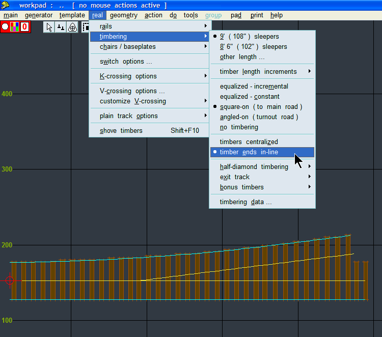 Normally centralized timbering is used when timbers are skewed (equalized timbering), and timber ends are in line when timbers are square (square-on timbering). But Templot doesn't make this change for you (perhaps it should?), and you can use either option with whichever timbering style you prefer or in accordance with your prototype. If you want a guide line along the timber ends, the easiest way is to create a dummy template and change the rail-top width setting (real > rails > rail section data...) to a silly dimension. For P4, S7, etc., that dimension is 25.75" for 9ft timbering and 22.75" for 8ft-6in timbering. For other gauges adjust these dimensions accordingly. Then you can omit all rails except the stock rails (do > omit rails and joint marks), and in the generator settings you can change to generating the rail outer edges only. The result is as in the screenshot above. Store this as a dummy template behind the one you are working on, with or without the timbering as appropriate. regards, Martin. |
||
|
posted: 7 Apr 2008 23:12 from: Stewart McSporran click the date to link to this post click member name to view archived images |
Hi Martin, Thanks for the reply. I can see how the timber ends in line helps with the sleepers along the main road but I'm afraid that I don't see how it helps for the timbers in the turnout road. They still need to be thrown. I did try throwing them by the difference between their original length and the new 108" length, but when you start rotating them they're never quite right. I like your simpler idea for creating the timber end guide template. I'll update the web page the next time I create one. regards Stewart |
||
|
posted: 7 Apr 2008 23:34 from: Martin Wynne
click the date to link to this post click member name to view archived images |
Stewart McSporran wrote: I can see how the timber ends in line helps with the sleepers along the main road but I'm afraid that I don't see how it helps for the timbers in the turnout road.Hi Stewart, It doesn't. That's why I suggested a method for a guide line. Interlaced timbering is very much a minority requirement, but I will try to add some additional options in the next pug to make it faster to do. If you don't want a single curvable template, you might find it faster to overlay two lots of plain track as partial templates. You would still need to shove the sleepers along, but they would all be the required length, and only a few would require any twisting, and probably none would need throwing. tools > make split > make plain track turnout road > on internal geometrical radius If it's greyed out, extend some approach track (F3) first. regards, Martin. |
||
|
posted: 17 Aug 2009 00:46 from: sierrasmith71 click the date to link to this post click member name to view archived images |
Stewart McSporran wrote: I've written up some notes on how I create interlaced sleeper turnouts with Templot and posted them on my website.Stewart: I am planing a small On30 layout that will use interlaced (zippered) sleepers (ties) on the the turnouts. The link referenced is not working, at least it does not for me. I would like to see how managed to create these! David |
||
|
posted: 17 Aug 2009 01:25 from: Martin Wynne
click the date to link to this post click member name to view archived images |
sierrasmith71 wrote:I am planing a small On30 layout that will use interlaced (zippered) sleepers (ties) on the the turnouts. The link referenced is not working, at least it does not for me. I would like to see how managed to create these!Hi David, Stewart had some web domain problems. The page you want is now at: http://grotsoft.net/Railways/Templot/InterlacedSleeperTurnouts.aspx I have now edited the links in this topic to match. regards, Martin. |
||
|
posted: 17 Aug 2009 09:37 from: Stewart McSporran click the date to link to this post click member name to view archived images |
Thanks for updating the links Martin (How on earth did you discover I'd registered grotsoft.net? I only did it a few days ago!). I was in hospital (car crash) when the .com domain expired and by the time I was discharged these *#$%#$%s had re-registered it from under me. It turns out you have absolutely no rights to a domain (unless it infringes trade marks) even if you created it in the first place. I didn't even bother asking how much they wanted for it; no way am I rewarding that sort of scum level business. David, hope you found the article useful. Stewart |
||
|
posted: 12 May 2010 20:00 from: weecaleypug click the date to link to this post click member name to view archived images |
Hi Martin Try as I might, I just cannot access this page. I have tried every method I know. Can you or anyone out there, help, please? Cheers Jim Martin Wynne wrote: sierrasmith71 wrote:I am planing a small On30 layout that will use interlaced (zippered) sleepers (ties) on the the turnouts. The link referenced is not working, at least it does not for me. I would like to see how managed to create these!Hi David, |
||
|
posted: 13 May 2010 08:16 from: Martin Wynne
click the date to link to this post click member name to view archived images |
weecaleypug wrote: Try as I might, I just cannot access this page. I have tried every method I know. Can you or anyone out there, help, please?Hi Jim, It seems Stewart's web site is offline. No doubt he will reply soon. In the meantime I have found a copy of the text, but not the images unfortunately. Here's the text only: _______________________ Designing Interlaced Sleeper Turnouts with Templot_________________________________________ regards, Martin. |
||
|
posted: 13 May 2010 11:34 from: Bruce Fletcher
click the date to link to this post click member name to view archived images |
weecaleypug wrote: Hi Martinhttp://www.grotsoft.net is unavailable at the moment. |
||
|
posted: 19 May 2010 21:26 from: Stewart McSporran click the date to link to this post click member name to view archived images |
Hi, I've been away for a while and missed this. First of all could Bruce or Martin please remove the address from the whois record in the above post? I appreciate it's available on whois but I'd rather not have it posted all over. My Grotsoft site wasn't paying its way, so I let it die. I have a back up of the article somewhere; I'll dig it out and post it on my company website over the weekend. I'll let you know here when I've done this. regards Stewart |
||
|
posted: 10 Jul 2010 08:26 from: Mike Waldron
click the date to link to this post click member name to view archived images |
where's your website gone now? <Mike |
||
|
posted: 12 Jul 2010 17:35 from: Mike Waldron
click the date to link to this post click member name to view archived images |
but where has the website gone? Mike Waldron |
||
|
posted: 3 Aug 2010 22:38 from: Richard_Jones
click the date to link to this post click member name to view archived images |
Hi for what the're worth, here's some photos taken at Northiam (KESR) probably mid to late 70's of an interlaced sleeper turnout, these are for my other layout, where I have already built the track, prior to signing up for Templot - I'll take a photo of the model turnouts when I track them down in the loft! best wishes Richard1763_031825_590000000.jpg 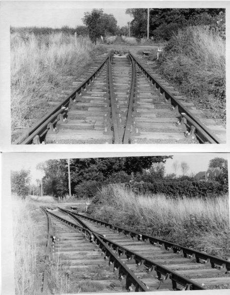 |
||
| Last edited on 3 Aug 2010 23:26 by Richard_Jones |
|||
|
posted: 4 Aug 2010 07:36 from: Mike Waldron
click the date to link to this post click member name to view archived images |
That's the very first one I've seen in real life, so to speak. Thanks for that. Mike |
||
|
posted: 4 Aug 2010 07:51 from: Martin Wynne
click the date to link to this post click member name to view archived images |
Mike Waldron wrote: That's the very first one I've seen in real life, so to speak.Hi Mike, There are some more pictures in this topic: topic 208 regards, Martin. |
||
|
posted: 4 Aug 2010 22:13 from: Richard_Jones
click the date to link to this post click member name to view archived images |
Here's the EM gauge ones I built rather longer ago than I care to remember - they should have been laid on the layout by now! 1763_041713_410000000.jpg 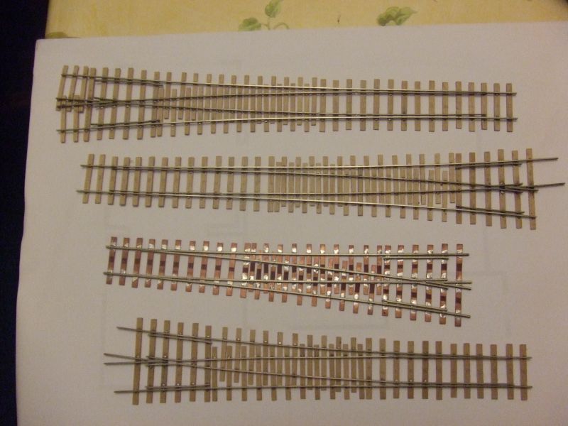 |
||
|
posted: 6 Aug 2010 15:08 from: Jim Guthrie
click the date to link to this post click member name to view archived images |
Here is an interlaced crossover which I made recently - in S scale using the new S Scale Society rail and chairs. The turnouts are based on a tracing of a Caledonian drawing which I got from a member of the Caledonian Railway Association.25_061004_300000000.jpg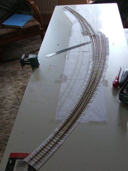 The radii are quite tight for S scale so the crossing angles are quite acute being 1:12 and 1:16. Jim. |
||
| Last edited on 6 Aug 2010 15:12 by Jim Guthrie |
|||
|
posted: 9 Mar 2016 20:03 from: mikewturner click the date to link to this post click member name to view archived images |
Hi guys I realise this an old thread so wondered if Stewart's interlacing notes are still regarded as the best way to do this given that Templot has moved on somewhat since then? Regards Mike |
||
|
posted: 10 Mar 2016 03:45 from: Martin Wynne
click the date to link to this post click member name to view archived images |
mikewturner wrote: I realise this an old thread so wondered if Stewart's interlacing notes are still regarded as the best way to do this given that Templot has moved on somewhat since then?Hi Mike, Stewart's web site is long gone, so we have only the plain text version which I posted above: topic 401 - message 6692 I can't think of any significant changes in Templot which would over-ride that. It is now much easier to adjust the check rails, of course. Unfortunately there is no commonality of prototypes for sleepered turnouts (interlaced), every company had its own approach. So it's not likely much could be added to Templot beyond the existing functions. Essentially you need a prototype drawing, scanned and loaded as a background picture shape, and then add bonus timbers as necessary and shove them into position. You could change all the timber spacing settings to half their usual values, so that you get double the usual number of timbers. This would avoid adding bonus timbers one at a time, but they would still need shoving into position. regards, Martin. |
||
|
posted: 11 Mar 2016 08:33 from: mikewturner click the date to link to this post click member name to view archived images |
Hi Martin Thanks for the advice, I hadn't thought of the reduced sleeper spacing to get the bonus timbers all at once so that's a great tip. My interest is with the Scottish companies and the struggle seems to be getting an original drawing to work from. I have got the NERA reprint which is a great start, have seen odd 'part' drawings from the old p-way site and it would appear from reading various postings here and on other forums that some Caledonian, Great North of Scotland and North British information exists possibly in archives but I do not know where. An ex BR engineer provided the attached from his collection which although not really of use to me might help others as it gives a different approach to the sleepering from the LNER. Regards Mike |
||
|
posted: 11 Mar 2016 08:42 from: Martin Wynne
click the date to link to this post click member name to view archived images |
Hi Mike, Attached? You may find this topic on the Western Thunder forum of interest: http://www.westernthunder.co.uk/index.php?threads/a-venture-into-the-garden.4597/page-6 There has been some discussion of the Scottish companies practice on that forum. regards, Martin. |
||
|
posted: 11 Mar 2016 08:47 from: mikewturner click the date to link to this post click member name to view archived images |
Hi Martin I'm trying honest but the wifi on the train keeps dropping out :-( might have to add the attachment this evening. I have been reading that thread but again no real reference to where drawings have come from, time for some PMs I think. Regards Mike |
||
|
posted: 11 Mar 2016 08:50 from: mikewturner click the date to link to this post click member name to view archived images |
Fingers crossed | ||
| Attachment: attach_2240_401_LNER_TURNOUTS_WITH_USE_OF_SLEEPERS_F.pdf 290 | |||
|
posted: 11 Mar 2016 08:58 from: Martin Wynne
click the date to link to this post click member name to view archived images |
Hi Mike, Many thanks for that, downloaded here fine. And very interesting to see an LNER drawing for a sleepered turnout with REA switches. I would have assumed that after grouping they continued only with the NER original designs. I also noticed the use of smaller M1 chairs on sleepers instead of the usual wider L1 bridge chairs on timbers. Given that drawing, I may try to add something in Templot to correspond. Which doesn't help you with the Scottish stuff though. Thanks again, Martin. |
||
|
posted: 11 Mar 2016 13:46 from: Jim Guthrie
click the date to link to this post click member name to view archived images |
mikewturner wrote: I have been reading that thread but again no real reference to where drawings have come from, time for some PMs I think. Mike, For the 1:32 scale turnouts shown in that thread I used a trace of an official drawing of a Caledonian turnout which was given to me my Jim MacIntosh, Chairman of the Caledonian Railway Association. The original is held in the National Archive of Scotland as RHP120106 http://oldpway.info/lists/NRS_NAS_RHP120106_record.pdf The trace is a hand drawn copy of the original document but it has a scale attached and is probably pretty accurate considering that permanent way construction of the time didn't conform too much to standards.25_110830_580000000.jpg 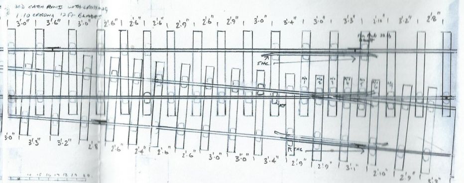 25_110833_140000000.jpg 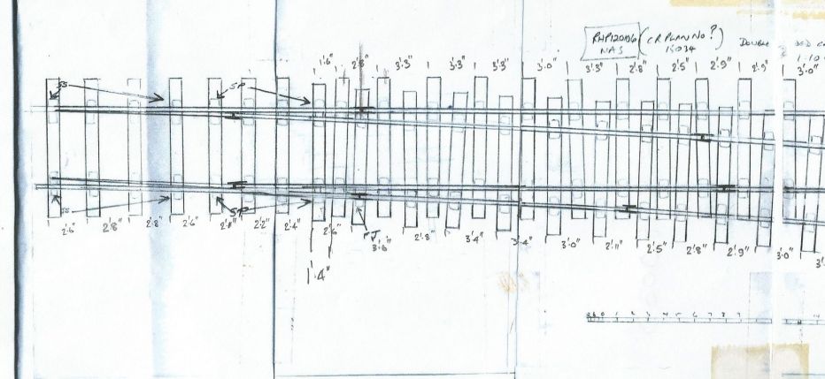 This is a scan from the print I made originally from the file sent to me so the quality isn't all that good. I can't find the original file - I suspect it is somewhere on the hard disk of my previous PC. The URL shown for the original in NAS looks interesting but I suspect that this might have been the only Caledonian drawing contained in that list since it was the CRA doing a search. (A minute or two later) I find that I am the source for the drawing on the OldPWay site. http://oldpway.info/drawings/CalR_ilace_ctchpnt_12ft_1in10.pdf Jim. |
||
| Attachment: attach_2241_401_CalTurnoutTrace-02.jpg 325 | |||
| Last edited on 11 Mar 2016 13:53 by Jim Guthrie |
|||
|
posted: 13 Mar 2016 21:52 from: mikewturner click the date to link to this post click member name to view archived images |
Hi Jim Thanks for the reply and file. I honestly missed the link to the drawing on old pway even though I've scoured the web for info. I will print it off tomorrow and then look to import it to Templot and design over it as suggested by Martin. As a matter of interest what radius are you using at the end of your checkrails? Regards and many thanks Mike |
||
|
posted: 13 Mar 2016 22:58 from: Jim Guthrie
click the date to link to this post click member name to view archived images |
mikewturner wrote: As a matter of interest what radius are you using at the end of your checkrails?Mike, You've just reminded me that I haven't decided what radius to use. I've just popped outside to remind myself of what I have done - I store the track on the baseboards outside - plenty of room out there and that's where they are going to finish up in any case. I've gone back to the drawings on the oldpway site and one of them gives a largish drawing of a crossing nose and wing rails with some dimensions so it should be possible to work out what the bend length and radius should be to give a distance of 3 1/2" at the end of the flare. http://oldpway.info/drawings/1900pc_pl02_CalR_xings.pdf Martin might take note of this and then we might get a "Flared ends curved" entry in the Real menu. Jim. |
||
|
posted: 15 Mar 2016 09:14 from: Jim Guthrie
click the date to link to this post click member name to view archived images |
mikewturner wrote: As a matter of interest what radius are you using at the end of your checkrails?Mike, I've just copied that crossing drawing into my CAD program and found that the radius of the end of the check rail/wing rail is about 2' 6" on the outer side of the curve on the rail. The curve on the rail extends until there is a gap of 3 1/2" between the end of the check rail and the running rail. Jim. |
||
|
posted: 15 Mar 2016 20:49 from: DerekStuart
click the date to link to this post click member name to view archived images |
If it's any help, I uploaded some links to photos that I found of NER interlaced. You should be able to find the post in the "prototype pictures" sub forum here. |
||
|
posted: 17 Mar 2016 01:37 from: John Palmer click the date to link to this post click member name to view archived images |
About 20 years ago a friend and I measured a turnout at Rannoch which, if it was not a North British original, appeared to follow closely what I have observed of that company's permanent way construction practice. Jim's reference to an end-of-flare gap of 3.5" is interesting. On the Rannoch turnout that gap was consistently 5" on all flares. I didn't attempt to establish a radius for the flares on site, and haven't done so subsequently. For what it's worth, my notes indicate that wing rail flares commenced 9.5" short of the end of the flare, whilst in the case of the check rails the commencement point was in three cases 11.5" from the end of flare, and in one 11.25". I agree that cosmetically it would be nice for Templot to offer the facility to show such flares as having a smooth constant curve, though I suspect we enthusiasts of Scottish track are too uncommon to warrant this! I also agree about how difficult it can be to get such smooth curvature into flare in a controlled way (I'm working in 4mm : 1') - and this even though I've knocked myself up a bending tool. Problems I have had with interlaced timber shoving include getting the shoved sleepers properly centralised and properly at right angles to the line of rail. To mitigate this, I have curved template so that the diverging road lies as nearly straight as I am able to get it, as this assists me considerably in overcoming both these difficulties. Once the shoving is done, I re-straighten the template before saving it as a library item. That way, for the limited range of crossing angle/switch combinations with which I am working, it is simplicity to add a new turnout into a layout with interlacing already in situ. |
||
|
posted: 17 Mar 2016 10:48 from: Jim Guthrie
click the date to link to this post click member name to view archived images |
John Palmer wrote: Jim's reference to an end-of-flare gap of 3.5" is interesting. On the Rannoch turnout that gap was consistently 5" on all flares. I didn't attempt to establish a radius for the flares on site, and haven't done so subsequently. For what it's worth, my notes indicate that wing rail flares commenced 9.5" short of the end of the flare, whilst in the case of the check rails the commencement point was in three cases 11.5" from the end of flare, and in one 11.25".John, I took the 3 1/2" measurement from the Caledonian drawing I referenced earlier. I would have expected the measurement to be larger. I tend to think of the gap at the end of check and wing rails to be twice rail head width, which is close to your 5" measurement, and which is easily gauged by eye when making the flare. On my first designs of interlaced turnouts, I created a template where the sleepers on the main road of the turnout only were positioned then I superimposed a length of plain track with the rails suppressed to represent the sleepers on the diverging road. This meant that the sleepers were at right angles to the centre line of the diverging route and they only needed a small amount of shoving along the route to get them properly interlaced with the sleepers on the main road. But this method meant that I had two templates for every turnout and I moved on to creating a template with the interlaced diverging route sleepers so that all sleepering detail was on one template. I didn't have too much problems getting the sleepers at right angles to the route centre line but I could have laid a guide using a length of plain track as in my first designs. Jim. |
||
|
posted: 17 Mar 2016 11:52 from: John Palmer click the date to link to this post click member name to view archived images |
A neat trick to get the alignment right! Thanks, Jim. | ||
|
posted: 20 Mar 2016 13:32 from: mikewturner click the date to link to this post click member name to view archived images |
Hi Jim Thanks for checking that measurement and you too John for your measurements at Rannock, did yu take any photos of the latter you could share? Looking at the NERA drawings it would appear the Scottish companies were not the only ones to have 'flared ends curved' as Jim calls them, these show the centre section of the checkrail being parallel to the stock rails, a section either side of this flared at maybe 1:20 (sorry not clear on my print) then the ends curved on a 2ft radius. The attached extract from a midland drawing of a 1 in 9 common crossing also shows curved ends to the wing rails at 18in radius. Regards Mike |
||
| Attachment: attach_2247_401_mid_1in9_common_crossing_extract.jpg 923 | |||
|
posted: 23 Mar 2016 15:21 from: John Palmer click the date to link to this post click member name to view archived images |
Mike, I've previously posted a photograph of the heel plate commonly found on North British turnouts here, which you may not have seen. Here's a further shot showing the flaring on one of the Rannoch turnout's wing rails: 2129_231014_580000000.jpg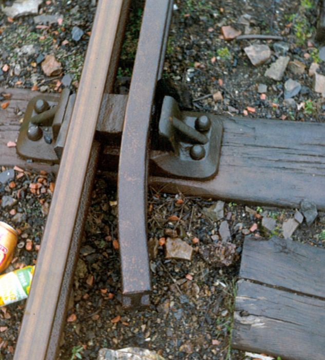 And here is a shot showing the common crossing:2129_231017_590000000.jpg 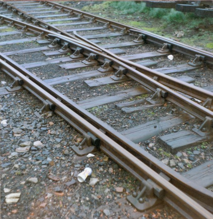 I have a few further photographs of this turnout, but each needs a little 'massaging' to bring it within permitted size limits. Anything in particular you would like to see? |
||
|
posted: 23 Mar 2016 17:22 from: Jim Guthrie
click the date to link to this post click member name to view archived images |
John Palmer wrote: We won't know until we see them. Jim. |
||
|
posted: 23 Mar 2016 21:03 from: Andrew Barrowman
click the date to link to this post click member name to view archived images |
Did someone spray that turnout with varnish to make it look pretty? On a more serious note, I noticed on Mikes shot of the MR crossing that the knuckle sits on a fancy chair and the bends in the wing rails don't appear to have a radius. |
||
|
posted: 23 Mar 2016 21:13 from: mikewturner click the date to link to this post click member name to view archived images |
Jim Guthrie wrote:John Palmer wrote:We won't know until we see them. What Jim said!!! A shot looking along the point from the toes would be nice. Regards Mike |
||
|
posted: 23 Mar 2016 21:14 from: mikewturner click the date to link to this post click member name to view archived images |
Andrew Barrowman wrote:Did someone spray that turnout with varnish to make it look pretty? Hi Andrew The final bend is shown as 18in radius? Regards Mike |
||
|
posted: 23 Mar 2016 23:01 from: Andrew Barrowman
click the date to link to this post click member name to view archived images |
mikewturner wrote: Andrew Barrowman wrote:Hi Mike, Agreed, but I was referring to the bend in the wing rails at the knuckle on the 2C9 chair. I understand that it's common for the rails to be bent to some radius at that position, but on your example it looks like they have a sharp bend. I just thought it was interesting Cheers! Andrew |
||
|
posted: 24 Mar 2016 01:15 from: John Palmer click the date to link to this post click member name to view archived images |
I am hoping that by dropping the jpeg quality by no more than one percentage point I have brought my other shots within permitted limits whilst preserving such quality as they have. Here we go... Switch viewed from heel to toe: 2129_231947_370000000.jpg 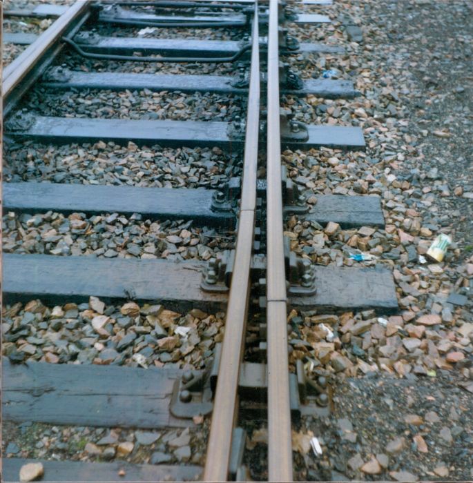 Switch viewed from toe to heel:2129_231950_190000000.jpg 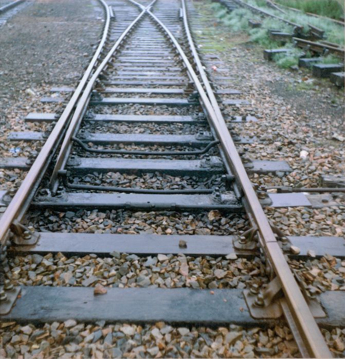 General view with replacement on bank alongside:2129_231955_190000000.jpg 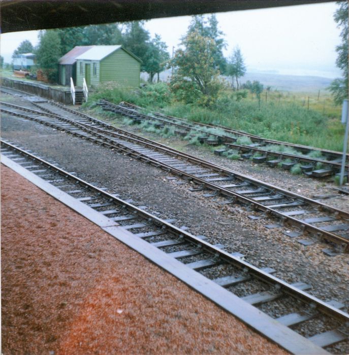 View from the bank:2129_231956_500000000.jpg 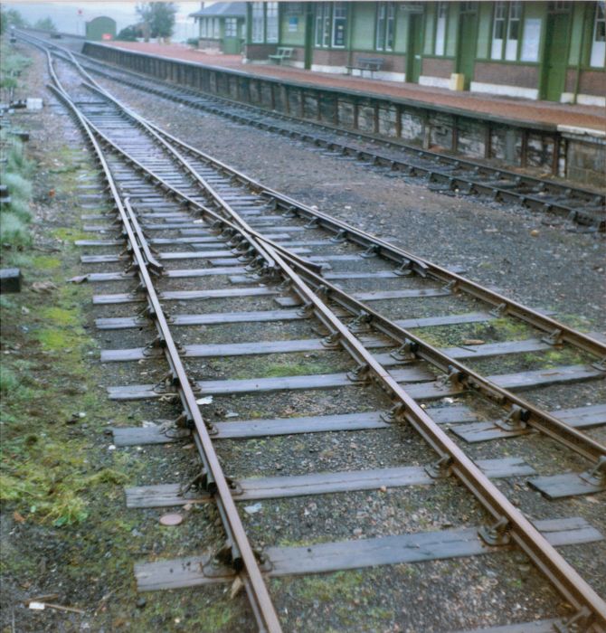 Partial view of knuckle showing Y, X, A, B, C, and D chairs:2129_231959_120000000.jpg 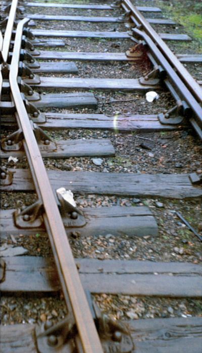 Those North British chair castings are quite distinctive - a pity nothing resembling them is available to the modeller. The switch arrangement comprising 4 pairs of slide chairs appears from my observations to have been widely adopted on NBR lines over a wide range of leads. It hadn't previously occurred to me that the track looks as though it has just received a coat of varnish. One of my abiding memories is that it was, as the Irish say, a soft day, with plenty of mist and low cloud hanging on the Moor, so that everything was well watered. Another memory is that we were beset by thick clouds of midges. At the time I was still a smoker and sought to keep them at bay by surrounding myself in clouds of cigar smoke, but at intervals the constant prickle of of their assault became so intense that we were compelled to seek refuge on the platform. Still, with replacement of this elderly piece of trackwork apparently imminent, I think it was worth it to make the record that we did. |
||
|
posted: 24 Mar 2016 08:49 from: mikewturner click the date to link to this post click member name to view archived images |
Andrew Barrowman wrote:mikewturner wrote:Andrew Barrowman wrote:Hi Mike, Apologies Andrew I misunderstood what you said, yes sharp bend not radiused Regards Mike |
||
|
posted: 24 Mar 2016 08:55 from: Jim Guthrie
click the date to link to this post click member name to view archived images |
John, Many thanks for these - particularly for the shot of tne switch and the stretcher rods/tiebars. I'm at the point of designing these for my 1:32 pointwork and was looking for some detail of Scottish practice. Martin provided details of Midland practice a while ago and your pictures show that Scottish practice was similar.. Jim. |
||
|
posted: 25 Mar 2016 04:27 from: Andrew Barrowman
click the date to link to this post click member name to view archived images |
Another interesting detail is that there don't seem to be any "flare chairs" on the wing rails, or on the check rails. It looks like the flare only starts beyond the last chair. I have a (very) vague recollection that the Saucel Goods on the former G&SWR that I spent many hours observing had similar turnouts. Unfortunately, I was not even a teenager at the time, so I didn't pay too much attention. |
||
|
posted: 25 Mar 2016 15:01 from: mikewturner click the date to link to this post click member name to view archived images |
Hi John Thanks for the photos they are excellent and open up a few more questions. In the shot taken from the bank it would appear that the wing rails are of different lengths. I know this is something raised by Jim in another topic either on here or Western Thunder and in some photos he was using it could have been a trick of the angle but here we have one you've measured so can you confirm this is the case please? The chairs are as you say very distinctive and wouldn't even lend themselves to an etch along the lines of the Masokits range due to the rib. Jim, I note you picking up on the connecting rods, whilst the attached are L&Y they may be interest as another example. I have also included a drawing for switches which is interesting as it shows a 'point guard' to stop the tips lifting. Regards Mike |
||
| Attachment: attach_2252_401_LANCASHIRE_AND_YORKSHIRE_RAILWAY__-_PERMANENT_WAY_-__CONNECTING_RODS_F.pdf 352 | |||
|
posted: 25 Mar 2016 15:03 from: mikewturner click the date to link to this post click member name to view archived images |
Sorry didn't realise could only add 1 attachment per message. Mike |
||
| Attachment: attach_2253_401_LANCASHIRE_AND_YORKSHIRE_RAILWAY__-_PERMANENT_WAY_-_GENERAL__ARRANGEMENT_OF_POINTS_F.pdf 316 | |||
|
posted: 25 Mar 2016 21:54 from: Jim Guthrie
click the date to link to this post click member name to view archived images |
mikewturner wrote: Jim, I note you picking up on the connecting rods, whilst the attached are L&Y they may be interest as another example. I have also included a drawing for switches which is interesting as it shows a 'point guard' to stop the tips lifting.Mike, Many thanks for that. The L&Y rods look very similar to the Caledonian ones with swan neck ends and your drawing will provide a good reference to calculate sizes. Saved in my Caledonian track folder for future use. Jim. |
||
|
posted: 26 Mar 2016 02:20 from: John Palmer click the date to link to this post click member name to view archived images |
My measurements of the Rannoch turnout include the length of each flaring (details of which I gave in my post #31 above) and also the distance from each check rail end to the transverse centre line of the nearest check chair. In each case, the check chair C/L to check rail end measurement exceeds the length of flaring by between 4” and 8.75” (that 4” difference I find bit suspect), so I think it’s safe to deduce from this that in all cases the flaring starts beyond the point at which it is held in the nearest check chair, and that consequently, as Andrew has noted, there are no ‘flare chairs’ – that must have simplified upkeep of the chair inventory. In addition, we took measurements of the pitch between the centres of each chair in the formation. From this it’s possible to calculate the length of the check rails. Mike is correct: they are different, and this is primarily due to the fact that the main road check rail is held by only 5 check chairs, whilst the diverging road check rail is held by 6. Since the sleepers are all pitched about 3’ apart in the area of the check rails this should mean a difference in check rail length of approximately 1 sleeper pitch. The actual measurements in my notes are as follows, beginning and ending with the dimension of check chair C/L to check rail end, with distances between each check chair C/L between these figures. Reading from the toe end towards the vee, the dimensions measured were: Main road: 19.5”+37.75”+34.75”+34”+36”+15.5” = 177.5” = 14’ 9.5” Diverging road: 18.25”+33”+34.75”+36.75”+36”+35”+17” = 210.75” = 17’ 6.5” This pretty much bears out my initial estimate that one check rail is about 3’ (one sleeper pitch) longer than the other. It may be unwise to assume that such a difference in check rail length or, indeed, any other part of the Rannoch turnout’s design is necessarily representative of practice on North British lines. For example, I have a couple of drawings of NB track dating from 1900-1901 which show crossings with check rails of apparently the same length carried on only four check chairs, suggesting either that the Rannoch arrangement was exceptional or, if it was representative, that it reflected changes in evolving North British S&C practice – or possibly that of the LNER’s Southern Scottish Area. Certainly the switch arrangements shown in the c.1900 drawings seem to have evolved subsequently, as they are significantly different from those of the Rannoch turnout which, as I mentioned, does appear to be representative of switches visible in photographs of a wide range of locations on the North British network. In particular, the same stretcher arrangement as can be seen on the Rannoch turnout is also visible in a number of other photographs showing switches on the North British system, involving the use of two stretchers of significantly different design. If anyone can provide them, I should be very pleased to see either a drawing or detailed photographs of the facing point lock stretchers used by the North British. |
||
|
posted: 28 Mar 2016 20:52 from: mikewturner click the date to link to this post click member name to view archived images |
And the LNW version Jim... Regards Mike |
||
| Attachment: attach_2254_401_LNW_point_and_stretcher_bars.pdf 233 | |||
|
posted: 29 Mar 2016 00:56 from: Jim Guthrie
click the date to link to this post click member name to view archived images |
mikewturner wrote: And the LNW version Jim...Mike, Many thanks. Jim. |
||
|
posted: 29 Mar 2016 12:11 from: mikewturner click the date to link to this post click member name to view archived images |
John Palmer wrote: View from the bank:2129_231956_500000000.jpg Hi John It was more the wing rails I was wondering about than the checks. In the view you posted from the bank, the left hand wing rail seems to be about 1 sleeper longer than the right hand one (similar length to the checks), is this borne out by your measurements? Also as a matter of interest what was the angle of the crossing and switch length here? Thanks for all your help with this, it's greatly appreciated. Regards Mike |
||
|
posted: 29 Mar 2016 13:35 from: John Palmer click the date to link to this post click member name to view archived images |
Mike, I think the apparent difference in the wing rails’ length is an optical illusion. My notes say that the length of the flaring on both wing rails was 9.5”, and I think this is borne out by the further photograph attached, which for some reason I must have overlooked when editing my other shots for posting here. As you can see, the flaring of both wing rail begins immediately beyond the point at which they are held in the ‘D’ chair. 2129_290831_050000000.jpg 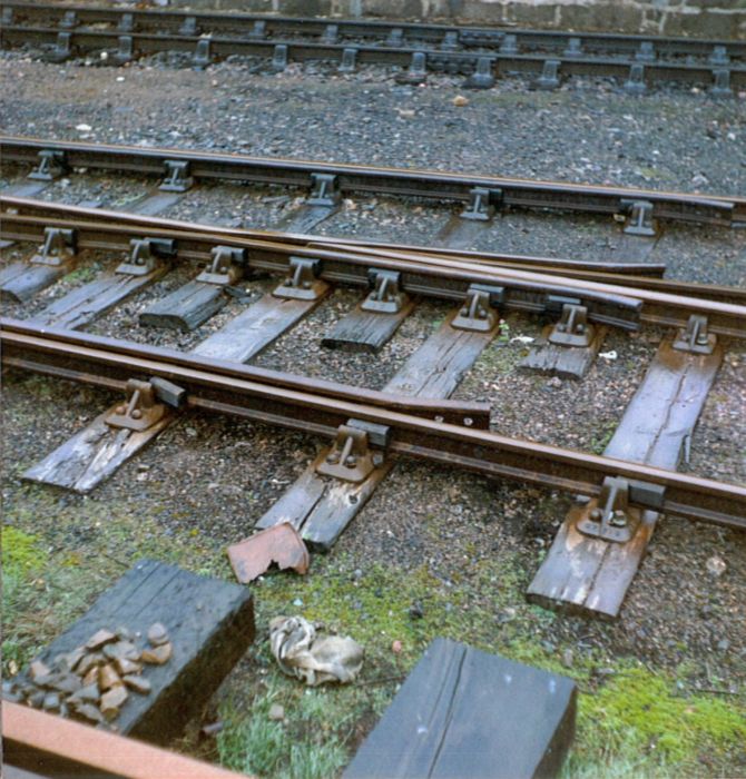 The crossing angle for the turnout was 1:7, switch length was 12’ and lead 50’. My notes tell me that the stock rail lengths paired with the switches via the heel plates were 17’ long. I greatly regret now that I did not measure the heel spread when I had the opportunity; my subsequent design work in Templot has been based on the assumption that this dimension was 4.5”. Although it’s apparent that on this turnout the stock rails were not joggled at the switch, I have a photograph of Chollerford on the Border Counties line showing a switch and catch tongue on both of which such joggles are plainly visible. It would be interesting to know more about the circumstances in which such joggled configurations came to be applied. |
||
| Last edited on 29 Mar 2016 13:36 by John Palmer |
|||
|
posted: 29 Mar 2016 16:54 from: Jim Guthrie
click the date to link to this post click member name to view archived images |
John Palmer wrote: It would be interesting to know more about the circumstances in which such joggled configurations came to be applied.John, Possibly joggling was only applied on main running line facing turnouts. Jim. |
||
|
posted: 29 Mar 2016 20:05 from: John Palmer click the date to link to this post click member name to view archived images |
Jim Guthrie wrote: John Palmer wrote:Jim, I've been trawling available pictures of North British locations in a quest for further such joggles, but in vain.It would be interesting to know more about the circumstances in which such joggled configurations came to be applied.John, In the case of the Chollerford photograph, the switches in question are not on the running line, but in the loops opposite the platform. In the photograph, one of the sidings is occupied by a rake of distinctly elderly looking arc-roofed carriages, leading me to wonder whether this may be a pre-First World War photograph. This, combined with my failure to find photographs showing other joggles, makes me suspect that the arrangement was uncommon and/or an early North British practice that fell out of favour. I had hoped that pictures of Chollerford/Humshaugh (as it became) in Middleton Press' "Hexham to Hawick" might shed further light. They don't, but what they do show is that the turnout forming the southern junction of the two loops mentioned featured very short check rails carried on three chairs apiece. |
||
|
posted: 18 Apr 2016 22:39 from: mikewturner click the date to link to this post click member name to view archived images |
Hi guys This photo shows the temporary station and sidings provided in connection with the hydro electric scheme at Inveruglas. It was opened in 1945 and if you look the turnout closest the camera is fully interlaced and would have been newly constructed at that time. Wartime economy or the Scottish companies just doing what they knew best? Regards Mike |
||
| Attachment: attach_2257_401_image.jpg 942 | |||
| Last edited on 18 Apr 2016 22:40 by mikewturner |
|||
|
posted: 19 Apr 2016 01:57 from: John Palmer click the date to link to this post click member name to view archived images |
Would that the Inveruglas photograph's resolution were slightly better and the full extent of the switch were visible! The timbering looks about right for a North British 12' switch, but the impression I get is that this may be a flexible switch rather than a loose heel switch as shown in the Rannoch pictures. Recently posted to Flickriver is a shot of Mallaig which may also be of interest and which is said to have been taken on 6 Sept 1969. A link is here. This shows that the turnout connecting No.2 Platform Line to the Main has been relaid with partial interlacing to a point short of the checkrails. |
||
|
posted: 19 Apr 2016 20:05 from: mikewturner click the date to link to this post click member name to view archived images |
Hi John Must admit I got the same impression about the switch! Maybe Martyn can cast his expert eye and give an opinion? The Mallaig shot is great thanks along with many others on that photostream, let's keep the interlaced stuff coming :-) Regards Mike |
||
|
posted: 21 Apr 2016 13:09 from: Jim Guthrie
click the date to link to this post click member name to view archived images |
mikewturner wrote: This photo shows the temporary station and sidings provided in connection with the hydro electric scheme at Inveruglas. It was opened in 1945 and if you look the turnout closest the camera is fully interlaced and would have been newly constructed at that time. Wartime economy or the Scottish companies just doing what they knew best? Mike, There are a good few examples of interlaced pointwork in Scotland which were being overhauled with more modern materials, if not being completely re-laid. A fellow S Scale Society member sent me a picture of a turnout at Blackford taken in the 1970s which showed such a turnout where the sleepers were in good condition and probably not the original Caledonian pre-Group ones, and the chairs looked like LMS or BR designs. The pictures were taken from the switch end so close detail of the actual crossing chairs was not available. After the Grouping you can probably accept that P&C work in Scotland continued on in the pre-Grouping fashion using existing stocks, being "out of sight, out of mind" of their new lords and masters way down south. One good source of information could be Richard Chown whose "Castle Rackrent" layout has appeared in magazines like the MRJ over the years. I believe that Richard worked with BR(S) in the track department and was a good source of information on what went on in Scotland in BR days. Unfortunately I can't find any mention of an email address for Richard. Jim. |
||
|
posted: 25 Apr 2016 18:53 from: allanferguson
click the date to link to this post click member name to view archived images |
Jim Guthrie wrote:mikewturner I spoke to Richard and he made the following comments: Hello Allan, Such is fame...... not a lot. The thing is that, just because there is a new standard it does not mean that everything is changed. The new standard would be used for new work, especially on sites that HQ is interested in. Beyond that a) there is new material to older standards still on hand, b) there is economy in re-using serviceable material recovered from main lines on more lightly trafficked routes, and c) the old District Engineers were a law unto themselves. Railway modellers have a fetish about standard turnouts. In pre-grouping times switches were sized by length, seven such on the NB, and crossing angles ran in ¼ steps from 1 in 2 to 1 in 13. Speeds through connections were 15mph, with the occasional expensive exception where operators really needed it, perhaps Uddingston on the Caley. The LNER issued the new standards, A to E switches, 1 in 4 to 1in 8 crossings in ½ steps then 9,10,11,12,14, and 16, in December 1933. The LMS perhaps a little earlier. The Southern probably much the same, the GW, as usual, not. My understanding is that the LNER continued to build sleepered leads. I think that the LMS was already a regular user of timbers – I think that the LNWR with its perfect track will have influenced that, though I have yet to find a good photo of late LNW S&C. The GW certainly already used timbers. The LNER was not wealthy. It had to spend carefully. The cost of crossing timbers, already more expensive than sleepers because of the larger section, goes up like Fibonacci numbers for every 6” you add to the length. Sleepered leads were more difficult to maintain, getting the shovels in to pack among all those sleeper ends – it soon showed if the crossing was not adequately supported. Having long timbers below the crossing seems so much better, but it is a delusion. They may be trying to bridge over lack of packing, until something breaks. If something was being laid as a sleepered lead at Blackford in the 1970s it was undoubtedly secondhand. Not in the running line I hope but in the yard, which by then as I recall was an Up refuge siding with a tamper siding off it. Something recovered from Fife, which for a while had been Perth’s, and something paid for out of the, by then Divisional, Engineer’s budget to avoid any embarrassing incident. Modellers also have a fetish about spacing the woodwork. Below the switch opening is regulated, starting below the switch toes and through to the heel because the blocks supporting the switch rail are sized. In the days of loose heel switches there would be a special chair at the heel, often gauging the back of the switch rail at check rail spacing. That heel chair might be large, on a single timber, or double over a pair of offset sleepers whose midline was the same again spacing as the slide chair sleepers. The sleeper count for each leg began again from the relevant one of the pair. At the crossing the spacing under the Y, X, A and B sleepers/timbers is fixed by the geometry of the crossing. The C, D etc ought to be too, but not if they have been pushed in to put a curve on one or both rails as they come away from the nose. Between the switch heel and the Z or Y chair the sleepers/timbers are spaced to fit the length, as near 2’ 6” spacing as can be contrived. I hope that you are with me – the A chair is under the crossing nose. In yards there may be bodging with non-standard leads and radii –bastard leads, not everything could be built strictly to the book. And that means whole stations, Liverpool Lime Street remained bullhead long after it was electrified in the 1960s because it was very much one-off. Practice today places the timber/concrete bearers at constant spacing from the switch toe to allow tampers to work right through. What nobody initially noticed is that this does not place a bearer under the crossing nose. They noticed when crossing started to crack though. I hope that this helps. Remember, it was all built by men with hammers, not micrometers. Best wishes Richard Richard has also let me see a copy of an NBR drawing showing switches and crossings, but it is very poor quality and I will need to work out how best to share it here. In the next instalment....... Allan F |
||
|
posted: 26 Apr 2016 12:39 from: Jim Guthrie
click the date to link to this post click member name to view archived images |
allanferguson wrote: The tamper was actually parked in the siding in the photograph. Jim. |
||
|
posted: 26 Apr 2016 17:06 from: allanferguson
click the date to link to this post click member name to view archived images |
Well, I'm trying to upload a drawing of NBR pointwork as above. It's a JPG file of 373 kb, and the program keeps telling me that the file I am trying to load is in a non allowed format....... should be JPG. I've given up now. Allan F (Frustrated of Fife) |
||
|
posted: 26 Apr 2016 17:24 from: Martin Wynne
click the date to link to this post click member name to view archived images |
Hi Allan, Rename the .JPG file as .jpg (lower case). Alternatively, if there is any punctuation or spaces in the file name, remove it/them (especially apostrophes and extra dots other than the one on .jpg). Why some cameras give image files upper-case file names is one of life's mysteries. On a Windows computer there is no difference, but that's not the case on the internet -- where they are two different things. However, I have now added JPG and JPEG to the allowed attachment list, so either case should work. For the image gallery I need to delve a bit. But generally it's best always to use lower case for file names (and no spaces or punctuation). Treat a file name as a symbol, rather than a title or description. regards, Martin. |
||
|
posted: 26 Apr 2016 18:05 from: allanferguson
click the date to link to this post click member name to view archived images |
Thank you, Martin -- helpful as always. I'll have another go once I've cooled down! Allan F |
||
|
posted: 27 Apr 2016 20:03 from: John Palmer click the date to link to this post click member name to view archived images |
Greatly looking forward to seeing Richard Chown’s NBR pointwork drawing – please persevere, Allan! A couple of years back I was assisting Chris Longley with the exhibition of his New Mere layout at the Wigan show. Behind us the backscene of Allendenac rose to the heights, and in the course of the exhibition I was able to have a useful chat with Richard about North British PW practice. He very kindly provided me with some information (I think about NB standard leads) which I wrote down but which I fear must have gone astray when we came to dismantling at the end of the exhibition. Been kicking myself ever since for that… I’m very grateful to Allan and Richard for the commentary posted. It had not occurred to me that the pitch between sleepers supporting the switch might be determined by the sizing of the blocks (is that another way of saying chairs?). I had thought that the slide chairs were all the same. As can be seen in the Rannoch turnout pictures, the special heel chair casting immediately follows the slide chairs, but I appreciate that in the case of a flexible switch there may be additional chairs which, by their geometry, may constrain the sleeper pitch. Fascinated to learn that there were seven lengths of NB switch and large heel chairs mounted on a single timber. I’ve only been able to observe the type spanning two sleepers, as illustrated in the photographs I’ve posted on this board. Another observation that intrigued me was that an attempt was made to maintain a 2’ 6” pitch (or thereabouts) to the sleepering between switch and crossing. On the Rannoch lead there were variations in this pitch, but all lay in the range 31.5” to 34.75” up to the crossing where, of course, the geometry of the crossing chairs enforced the amount of separation. This is appreciably more than Richard’s nominal value of 2’ 6”, so perhaps its builders were particularly affected by NBR/LNER considerations of economy. Loved the account of what happened when they tried maintaining a constant pitch of bearers under a modern turnout, so leaving the nose unsupported! |
||
|
posted: 27 Apr 2016 20:21 from: mikewturner click the date to link to this post click member name to view archived images |
Big thanks to Allan for contacting Richard and to Jim for making the suggestion in the first place. I too await the drawing with interest! Regards Mike |
||
|
posted: 27 Apr 2016 20:28 from: mikewturner click the date to link to this post click member name to view archived images |
In the meantime some 1958 images of Crianlarich from my collection | ||
| Attachment: attach_2261_401_image.jpg 208 | |||
|
posted: 27 Apr 2016 20:30 from: mikewturner click the date to link to this post click member name to view archived images |
And another | ||
| Attachment: attach_2262_401_image.jpg 222 | |||
|
posted: 27 Apr 2016 20:33 from: mikewturner click the date to link to this post click member name to view archived images |
And this is the scissors in 1936 - note the interlacing :-) | ||
| Attachment: attach_2263_401_image.jpg 279 | |||
|
posted: 27 Apr 2016 20:53 from: allanferguson
click the date to link to this post click member name to view archived images |
Herewith the drawing as promised -- sorry for the delay. Richard commented:- Hello Allan, The attached is NB dated 1901, showing how they timbered three pieces of S&C. You will note that they did need timbers in the diamonds, yet there is a sleeper right in the middle. I had to dig it out in order to do the job properly myself on the new layout. Nine foot switches, 1 in 5, 6 and 7 crossings. I ought to have the cloth-backed original somewhere, but cannot find it, and it has been lent to so many people over the years that I may no longer have it. So treasure this, and hope to read the various inscriptions if you can. Note that the crossing chairs sit on the sleepers of the diverging road, because they are on the skew, but not square to that road, in order to carry the chairs. I learnt that myself today. Best wishes Richard Note his comment re the quality of the print! Allan F |
||
| Attachment: attach_2264_401_NBRS&C0010.jpg 414 | |||
|
posted: 28 Apr 2016 00:45 from: John Palmer click the date to link to this post click member name to view archived images |
Allan, thank you for taking that trouble in posting Richard’s drawing – much appreciated, as are Richard’s supply of it and further comments. Points of interest to me that arise from it are: 1. The 16’ switch on the turnout bears a striking resemblance to the drawing of a NB switch provided by W.B. Worthington to the 1900 International Railway Congress and available from the oldpwayinfo website. Not really surprising since the drawings were prepared in contiguous years. 2. Like the 12’ switch on the Rannoch lead, in the 16’ switch the heel chair (spanning two sleepers) immediately follows the slide chairs, of which there is one additional pair in the longer switch 3. The pitch of sleepers through the switch must approach 3’ 4. I suspect the ‘Throw of Switch Blade’ dimension to be 3.5” , as on the switch drawn by Mr Worthington. Not a very large gap. 5. The largely illegible annotation along the 3rd sleeper of the switch probably notes the presence of an additional 1.5” stretcher rod for facing points, as on the Worthington drawing 6. The sleeper carrying the ‘B’ chairs on the diamond appears to be spliced at an angle to another sleeper across the remaining width of the formation. A half-lapped joint on the angle? 7. On the through road with slip drawing the ‘B’ chair is carried on what appears to be a crossing timber that extends across the full width of the formation. ‘A’ and ‘C’ chairs also appear to be carried on timbers of 9’ length but broader than the standard sleeper. 8. The through road formation appears to include timbers/sleepers of at least three different widths. 9. I don’t understand the expressions ‘single guarded’ and ‘double guarded’ and would be interested to learn what these mean. 10. Bit puzzled by Richard’s reference to how the crossing chairs sit on the diverging road. From my observation of the Rannoch turnout, I had always taken the base of these chairs to have been aligned so as to be square with the sleeper to which they were attached, and for the castings of such chairs to be designed accordingly. My observations have also suggested to me that the ‘A’ chair was usually (always?) carried on a sleeper spanning the main road. Can’t wrap my addled brain around whether this has implications for the ‘handing’ of sets of crossing chairs according to the flexure of the turnout. |
||
|
posted: 28 Apr 2016 00:47 from: John Palmer click the date to link to this post click member name to view archived images |
Mike, thank you for posting those interesting additional shots. In 4mm scale Ian Terrell can supply etched representations of that point lever - see this link Interesting to note that at the time of your photograph Crianlarich’s Up West Highland Line Home signal was still of Stevens LQ design. |
||
|
posted: 28 Apr 2016 00:57 from: Martin Wynne
click the date to link to this post click member name to view archived images |
John Palmer wrote: 9. I don’t understand the expressions ‘single guarded’ and ‘double guarded’ and would be interested to learn what these mean.Hi John, I believe this refers to the check rails (guard rails). The diamond-crossing has long continuous check rails on all rails through the K-crossings, back to the V-crossings. This is impossible for the slip of course, which shows more conventional short check rails. regards, Martin. |
||
|
posted: 28 Apr 2016 01:09 from: John Palmer click the date to link to this post click member name to view archived images |
Thanks, Martin, I did wonder whether it might be a reference to the check rail configuration. Typical of me not to notice the extended check rails on the diamonds, which I now notice are present both 'inside' and 'outside' the diamond; i.e. the checking of the acute crossings is also extended, as nearly as possible to the obtuse crossings. | ||
|
posted: 28 Apr 2016 07:20 from: mikewturner click the date to link to this post click member name to view archived images |
John Palmer wrote:Mike, thank you for posting those interesting additional shots. Hi John Bear in mind that shot is 1936 not 1958 as the others are. Regards Mike |
||
|
posted: 28 Apr 2016 08:48 from: Jim Guthrie
click the date to link to this post click member name to view archived images |
allanferguson wrote: Herewith the drawing as promisedAllan, I've already got a copy of that drawing - from a friend in Scotland. In the 1960s I did a survey of the Caledonian line from Crianlarich to Tyndrum with a view to modelling Dalmally station. I took a lot of pictures at the time - some of Dalmally signal box got into the recent Caledonian Railway Association signalling book. Another thing of note is a North British table of switch and crossing leads which appeared in the Gauge 0 Guild manual some years ago (it might still be included). The quality is very poor and would hardly be worth scanning, but I could copy the values into a new table if people are interested. Jim. |
||
| Last edited on 28 Apr 2016 08:50 by Jim Guthrie |
|||
|
posted: 28 Apr 2016 09:08 from: John Palmer click the date to link to this post click member name to view archived images |
Jim Guthrie wrote: allanferguson wrote:'Signalling the Caledonian Railway' is a veritable feast for signalling enthusiasts such as I, and all its contributors deserve congratulation! I have plenty of 'if only' moments about railway photographs I might have taken in my teens, but since none of my cameras offered more than 12 exposures per roll/cartridge I frequently found myself making difficult choices about what to shoot. Photographs of track? Why on earth would I think of taking those, given that it was a subject about which I knew nothing?Herewith the drawing as promisedAllan, I am wondering whether that table of North British S&C values may have been what Richard Chown showed me at the Wigan Show. If you wouldn't mind preparing a new table of them, Jim, I'd much appreciate it. |
||
|
posted: 28 Apr 2016 13:18 from: grahamroberts click the date to link to this post click member name to view archived images |
I have been following this topic with interest, although much of the technical detail is a bit over my head. One primary source which has not been mentioned so far is a small two-sided card document from the GNSR, "Crossing Leads and Cant on Curves" dated 8 Feb 1921, preserved in the O'Dell collection at Aberdeen University. It gives the radius in feet, and straight lead lengths, for crossing angles in whole steps from 1 in 6 to 1 in 18 and for 12ft, 15ft, 18ft and 21ft (I assume these are switch lengths). Only the combinations used in practice are provided. I think the document is interesting since it is obviously intended for daily use by men with shovels and hammers, rather than a drawing-office production. I attach the notes I made from it. The comments are verbatim from the original, and suggest that PW foremen were expected to use it as a guide rather than a prescription. Hope it adds a small further crumb of knowledge. By the way, there is still a partially-interlaced GNSR turnout on the Waterloo branch at Aberdeen, but it has probably been repaired many times and there are timbers under the crossing. regards Graham |
||
| Attachment: attach_2267_401_GNSR_point_leads_1921.pdf 201 | |||
|
posted: 28 Apr 2016 18:47 from: Jim Guthrie
click the date to link to this post click member name to view archived images |
John Palmer wrote: John, I've re-created the table in a spreadsheet and I've attached it as a zipped .xls file. I think it's all OK but at least the values are in series and you can usually work otu if there's been finger trouble in copying something. |
||
| Attachment: attach_2268_401_NBRTurnoutLeads.zip 204 | |||
|
posted: 28 Apr 2016 19:54 from: mikewturner click the date to link to this post click member name to view archived images |
Big thanks to Jim and. Graham for this latest info, we are certainly pulling stuff out the woodwork now! Regards Mike |
||
|
posted: 29 Apr 2016 09:03 from: John Palmer click the date to link to this post click member name to view archived images |
Jim, I can see at a glance that your NBR leads/radii table is enormously useful to me at least, providing as it does a framework within which the company's pointwork design and practice can be analysed. I fancy I may now have quite a bit of work to do in Templot reconciling my designs with the table! Thank you so much for taking the trouble to prepare and post this. Many thanks also to Graham for posting the GNSR table - it's going to be interesting to compare the values in this with those for the North British. Some noteworthy differences seem to be immediately apparent as regards approved switch lengths. |
||
|
posted: 4 May 2016 20:48 from: mikewturner click the date to link to this post click member name to view archived images |
Hi Guys Another Oban this time in 1982. And this looks like flexible switches to me too: http://www.flickr.com/photos/44232489@N02/26498297511/ Regards Mike |
||
|
posted: 5 May 2016 01:53 from: John Palmer click the date to link to this post click member name to view archived images |
I agree about the flexible switch for this turnout: 21 Points in the Oban box. But it's a rum arrangement to my eyes, with a mix of timbers and sleepers in which the sleepers appear redundant and complicate maintenance by obstructing access to the ballast. I wondered whether the sleepers were left over from a time when there were no through timbers, but it appears that they have the same pattern of chairs (3 fastenings) as the timbers, suggesting that, if this was formerly a Caledonian sleepered lead, the decision was taken at some point to replace the Caledonian chairs (? 4 fastenings). In that case, why restore the sleepers after re-chairing if you already have adequate support from the timbers visible in the photograph? Mike Morant's site provides a very nice shot of a diamond connecting Slow to Fast at Craigentinny, the link for which is here. It bears a very strong resemblance to the double guarded diamond shown in Richard Chown's drawing. |
||
|
posted: 5 May 2016 07:52 from: mikewturner click the date to link to this post click member name to view archived images |
Hi John Your spot on and I must admit I hadn't looked at it hard yet being excited that I'd found it! :-) if you look at the other photos there taken on the same day you will note some quite odd sleeper arrangements even in plain track which looks like timbers left in following recoveries. Regards Mike |
||
|
posted: 5 May 2016 08:16 from: mikewturner click the date to link to this post click member name to view archived images |
Hi John Ok just had a proper look at Oban and it appears to make no sense? The point seems to be standard timbered but with some sleepers interlaced, I wonder if they are being used to hold the gauge in lieu of tie bars? Regards Mike |
||
|
posted: 5 May 2016 16:07 from: grahamroberts click the date to link to this post click member name to view archived images |
John Palmer wrote: Mike Morant's site provides a very nice shot of a diamond connecting Slow to Fast at Craigentinny, the link for which is here. It bears a very strong resemblance to the double guarded diamond shown in Richard Chown's drawing.Another shot showing the arrangement of interlacing on an NBR diamond reasonably clearly is here, at Melrose in the LNER era. |
||
| Last edited on 5 May 2016 16:09 by grahamroberts |
|||
|
posted: 5 May 2016 22:17 from: alan@york click the date to link to this post click member name to view archived images |
Not quite interlaced, but perhaps unlaced...a@y | ||
| Attachment: attach_2278_401_34c.JPG 459 | |||
| Last edited on 5 May 2016 22:19 by alan@york |
|||
|
posted: 5 May 2016 23:30 from: Jim Guthrie
click the date to link to this post click member name to view archived images |
alan@york wrote: Not quite interlaced, but perhaps unlaced...a@yAlan, ...but standard practice on some US railroads. Look at Page 5 on this PDF http://www.up.com/cs/groups/public/@uprr/@customers/@industrialdevelopment/@operationsspecs/@specifications/documents/up_pdf_nativedocs/pdf_up_std_5000.pdf It's actually a good way to get round a lot of difficult timber placement on more complex formations and it does cut down on the requirement for long timbers. Jim. |
||
| Last edited on 5 May 2016 23:32 by Jim Guthrie |
|||
|
posted: 6 May 2016 08:01 from: mikewturner click the date to link to this post click member name to view archived images |
alan@york wrote:Not quite interlaced, but perhaps unlaced...a@y Hi Alan That appears to be standard LNER practice and is shown in the NERA LNER Standard Railway Equipment - Permanent Way reprint in a drawing titled short timbering for crossover roads. I've got a copy of an original source somewhere and will dig out and post so as not to infringe any copyright. Regards Mike |
||
|
posted: 7 May 2016 08:07 from: mikewturner click the date to link to this post click member name to view archived images |
mikewturner wrote:alan@york wrote: As promised |
||
| Attachment: attach_2279_401_image.jpg 397 | |||
|
posted: 7 May 2016 08:10 from: mikewturner click the date to link to this post click member name to view archived images |
And a slightly different approach again from the LNER Standard Railway Equipment - Permanent Way series of drawings this time "method of timbering junctions and crossover roads | ||
| Attachment: attach_2280_401_image.jpg 405 | |||
|
posted: 7 May 2016 14:23 from: alan@york click the date to link to this post click member name to view archived images |
Thanks Mike, for the info. Now if only I'd had that earlier. My fault for not asking... |
||
| Attachment: attach_2282_401_SG104961_-_Copy.JPG 369 | |||
| Last edited on 7 May 2016 14:25 by alan@york |
|||
|
posted: 13 May 2016 00:34 from: allanferguson
click the date to link to this post click member name to view archived images |
John Palmer wrote:Allan, thank you for taking that trouble in posting Richard’s drawing – much appreciated, as are Richard’s supply of it and further comments. |
||
|
posted: 16 May 2016 17:51 from: John Palmer click the date to link to this post click member name to view archived images |
Very many thanks to Richard for his further commentary, and to Allan for posting it. Richard's comment upon point 10 is particularly useful in clarifying that generally there was no handing of the special chairs, but rather that sleepers on the diverging road would not lie square to the rail in order that they might be aligned so as to carry the full length of such chairs. That, of course, is going to mean that I shall have to re-visit the timber shoving on my Templot library templates for NBR turnouts - and will need a further review of those incorporated into my layout design, since most are curved formations with similar flexure! As to point 2, I have been very much aware of this restricted clearance - the same value as the crossing flangeway – and it is for this reason that I so much regret having failed to measure the heel spread on the Rannoch turnout, as it appears that this dimension radically affects the amount of clearance between stock rail and back of switch, at least in the case of loose heel switches. |
||
| Please read this important note about copyright: Unless stated otherwise, all the files submitted to this web site are copyright and the property of the respective contributor. You are welcome to use them for your own personal non-commercial purposes, and in your messages on this web site. If you want to publish any of this material elsewhere or use it commercially, you must first obtain the owner's permission to do so. |