Search
Martin Wynne
Admin
- Location
- West of the Severn UK
- Info
- .
Enjoy using Templot?
 Thanks.
Please do not send requests for help direct to me via email.
Post your questions on the forum where everyone can see them and add
helpful replies.
.
Having recently acquired a toy CNC miller, I'm now beginning to prefer the one-piece timbering bases in MDF or plywood, rather than the FDM 3D-printed option for Plug Track. This is EM gauge in MDF -- at this stage you have to imagine the ballast between the timbers:")
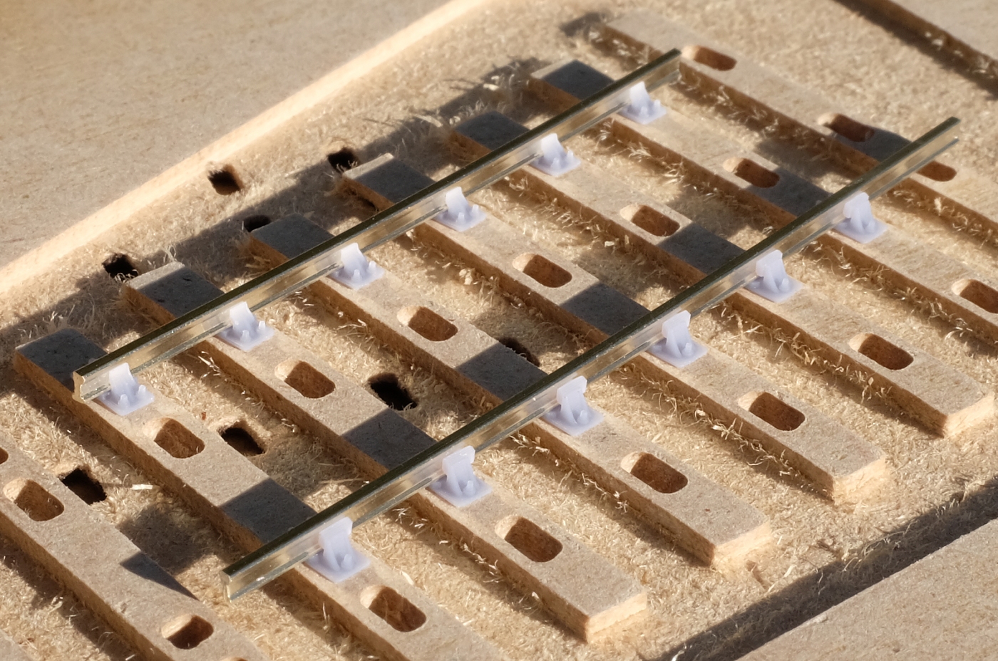
(The through holes are from some sockets on the other side of this bit of MDF.)
It's faster than the FDM printer, and the work area is significantly larger, and can be extended with expander kits. Unlike a laser-cutter the machine cost is comparable with an FDM printer. The only downside is that the process very noisy. More info:
https://85a.uk/templot/club/index.php?threads/cnc-milled-timbers-instead-of-laser-cut.276/
MDF doesn't have any actual grain of course, but when stained it has a pleasant wood-like surface texture which at normal viewing distance represents railway timbers very well. And unlike FDM printing you get sharp corners on the timbers.
But the most significant advantage is that it needs only a 2-D DXF file from Templot, which makes it much easier to envisage complex bespoke pointwork done this way. In fact existing BOX file projects could be used almost as-is for the 2-D exports (likewise for laser cutters). Including the automated tandems and slips:

It just needs changes in the code to put the right chairs in the right places. The BOX file doesn't need to change -- or any changes needed can be automated.
Whereas for the 3-D exports (for FDM printed timbering bricks) any complex Templot designs are likely to need some significant re-working to any shoved timbers and partial templates, to create a usable 3-D file.
Also of course, the idea of a solid one-piece timbering base is very appealing. Just plug in the chairs and rails, and screw it down to the baseboard. No messy gluing or weighting down, no templates or gauging. If the alignment is a bit out, just slacken the screws and adjust it.
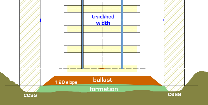
Which brings me to the actual subject line of this topic. Matching the level of such a one-piece base to adjacent flexi-track or other tracks. The above was cut in 3mm MDF. If you use 0.8mm ply timbers, that's going to need 2.2mm of trackbed underlay to bring the timber tops to the same height. If you use thicker 1.6mm timbers, only 1.4mm of underlay is needed. Neither of those are very convenient available thicknesses of cork. Nor are they thick enough to provide a proper ballast shoulder or cess.
It might be better to pack such a timbering base with card or foam to bring it to a more convenient height for the adjacent track. And/or use thicker MDF in the first place?
Just thinking aloud -- I've rather lost touch with current tracklaying practice and available trackbed underlays and thicknesses.
When I first thought of 3D track direct from Templot it seemed that the major issue would be the chairs. As it's turned out, the little Elegoo 3D printers work great, and the chair designs are all doable, if time-consuming. It's the timbering which has proved more problematic, with a lot of ifs and buts and alternative options.
Because after all that, you still need the FDM printer for the filing and bending jigs -- the CNC miller would hardly be strong enough for those. As I said, too many ifs and buts.
Martin.
Having recently acquired a toy CNC miller, I'm now beginning to prefer the one-piece timbering bases in MDF or plywood, rather than the FDM 3D-printed option for Plug Track. This is EM gauge in MDF -- at this stage you have to imagine the ballast between the timbers:
(The through holes are from some sockets on the other side of this bit of MDF.)
It's faster than the FDM printer, and the work area is significantly larger, and can be extended with expander kits. Unlike a laser-cutter the machine cost is comparable with an FDM printer. The only downside is that the process very noisy. More info:
https://85a.uk/templot/club/index.php?threads/cnc-milled-timbers-instead-of-laser-cut.276/
MDF doesn't have any actual grain of course, but when stained it has a pleasant wood-like surface texture which at normal viewing distance represents railway timbers very well. And unlike FDM printing you get sharp corners on the timbers.
But the most significant advantage is that it needs only a 2-D DXF file from Templot, which makes it much easier to envisage complex bespoke pointwork done this way. In fact existing BOX file projects could be used almost as-is for the 2-D exports (likewise for laser cutters). Including the automated tandems and slips:
It just needs changes in the code to put the right chairs in the right places. The BOX file doesn't need to change -- or any changes needed can be automated.
Whereas for the 3-D exports (for FDM printed timbering bricks) any complex Templot designs are likely to need some significant re-working to any shoved timbers and partial templates, to create a usable 3-D file.
Also of course, the idea of a solid one-piece timbering base is very appealing. Just plug in the chairs and rails, and screw it down to the baseboard. No messy gluing or weighting down, no templates or gauging. If the alignment is a bit out, just slacken the screws and adjust it.
Which brings me to the actual subject line of this topic. Matching the level of such a one-piece base to adjacent flexi-track or other tracks. The above was cut in 3mm MDF. If you use 0.8mm ply timbers, that's going to need 2.2mm of trackbed underlay to bring the timber tops to the same height. If you use thicker 1.6mm timbers, only 1.4mm of underlay is needed. Neither of those are very convenient available thicknesses of cork. Nor are they thick enough to provide a proper ballast shoulder or cess.
It might be better to pack such a timbering base with card or foam to bring it to a more convenient height for the adjacent track. And/or use thicker MDF in the first place?
Just thinking aloud -- I've rather lost touch with current tracklaying practice and available trackbed underlays and thicknesses.
When I first thought of 3D track direct from Templot it seemed that the major issue would be the chairs. As it's turned out, the little Elegoo 3D printers work great, and the chair designs are all doable, if time-consuming. It's the timbering which has proved more problematic, with a lot of ifs and buts and alternative options.
Because after all that, you still need the FDM printer for the filing and bending jigs -- the CNC miller would hardly be strong enough for those. As I said, too many ifs and buts.
Martin.
message ref: 2985