TEMPLOT 3D PLUG TRACK - To get up to speed with this experimental project click here.

  • The Plug Track functions are experimental and still being developed. Some of the earlier pages of this topic are now out-of-date.

    For an updated overview of this project see this post.   For some practical modelling aspects of using Plug Track see Building 3D Track.

    The assumption is that you have your own machines on which to experiment, or helpful friends with machines. Please do not send Templot files to commercial laser cutting or 3D printing firms while this project is still experimental, because the results are unpredictable and possibly wasteful.

    Some pages of this and other topics include contributions from members who are creating and posting their own CAD designs for 3D printing and laser-cutting. Do not confuse them with Templot's own exported CAD files. All files derived from Templot are © Martin Wynne.
  • The Plug Track functions are experimental and still being developed.

    For an updated overview of this project see this post.   For some practical modelling aspects of using Plug Track see Building 3D Track.

    The assumption is that you have your own machines on which to experiment, or helpful friends with machines. Please do not send Templot files to commercial laser cutting or 3D printing firms while this project is still experimental, because the results are unpredictable and possibly wasteful.

    Some pages of this and other topics include contributions from members who are creating and posting their own CAD designs for 3D printing and laser-cutting. Do not confuse them with Templot's own exported CAD files. All files derived from Templot are © Martin Wynne.

Building 3D track

Quick reply >

Martin Wynne

Admin
Location
West of the Severn UK
Info
.
Enjoy using Templot?
Thanks.

Please do not send requests for help direct to me via email.

Post your questions on the forum where everyone can see them and add
helpful replies.
.
This is a topic to talk about actually building track using 3D methods -- 3D-printing, laser-cutting, CNC-milling, etc.

Using both the built-in Plug Track functions in Templot in whole or part (still extremely experimental), see:

https://85a.uk/templot/club/index.php?forums/plug-track.34/

and additionally users own 3D developments and ideas.

I know a lot of users are getting very confused by all the different options and methods being discussed. I'm hoping that separating actual modelling and track construction topics from the topics about Templot software developments might add some clarity. Maybe. :unsure:

If you are posting in this topic, please make very clear in red ink whether your pictures and discussions are about your own 3D developments, or are derived from Templot plug track. Thanks.

Martin.
 
_______________
message ref: 4749
Hi Martin,

The ability to generate chairs is a fantastic step forward and I have been experimenting with this a little bit. I have an Anycubic Photon 3D printer and a Darkly Labs Emblaser 2 laser cutter and I am keen to explore the possibility of using these tools to create normal P4 track and, for now, preserving more traditional techniques for turnouts.

The Emblaser cuts card much easier than ply and I have used card extensively in the machine with shellac which produces a really strong end result. The photo below shows some 3D printed chairs from 228a together with some sleepers cut from 1.5mm mounting board. As you can see I have had to reduce the size of the socket hole in order to preserve a reasonably strong edge to the sleeper.

Is there anywhere in 228a which enables me to change the size of the plug on the chair base please? I have set the hole in the sleeper at 3mm x 1.5mm which should be just as strong as the size you are using but I can't see anywhere where the size can be changed - am I missing something please?

Ralph

20210801_142629.jpg
 
_______________
message ref: 2177
Is there anywhere in 228a which enables me to change the size of the plug on the chair base please? I have set the hole in the sleeper at 3mm x 1.5mm which should be just as strong as the size you are using but I can't see anywhere where the size can be changed - am I missing something please?
@ralphrobertson

Hi Ralph,

That looks great! Thanks for posting. :)

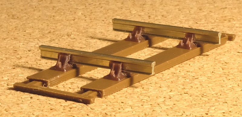
I'm aware that the chair plug size weakens plain track 10" sleepers. That's the reason for adding the bottom flanges on the 3D printed sleepers.

Currently the plug dimensions match the centres of the base corner radius on the chairs, i.e. 6" (2mm) wide and 12.5" (4.17mm) long. I'm sorry, at present there is no means to change that. There will be eventually some means to change almost everything, including fully-customizable chair designs, but we are not there yet.

That leaves the base overlapping the plug by 1" (0.33mm) all round, and I'm a bit reluctant to change that. I have made the base as close to scale thickness as I dare, and even now they are a bit fragile with the occasional corner breaking off (prototypical if it is only "occasional"). If the base overlap is increased by reducing the plug width, I fear it will be necessary to increase the base thickness even more to avoid damage.

The L1 bridge chairs have a larger corner radius, and a correspondingly wider plug overlap, but the sockets still get very close to the edge of the timber. I will cross that bridge (!) when I get to it. Fortunately L1 chairs are not used on 10" wide sleepers.

But all that will be up to the user in the end. It just takes time -- I wanted to get 228a released because all this has been in development for about 3 years now. I accidentally released some of it in 227a so there didn't seem much choice but to do a proper release with at least some intended functionality. It's also great to get some feedback such as yours, many thanks.

In the meantime you have a couple of options:

1. edit the DXF/STL files in a CAD package to reduce the plug width.

2. some plain track -- on soft ground, in tunnels, and under water troughs, was laid with 12" wide sleepers, also the end joint sleeper of some track panels was 12" wide. Strictly speaking that would require S1J chairs, but not always. You could try fitting the 6" wide plugs in 12" sleepers to create a short length of such track.

It might be some time before I can do a release with adjustable plug sizes, but I might be able to post a STL file with reduced plug widths shortly for you to try.

If you are using 1.5mm thick sleepers I suggest increasing the plug depth slightly -- that's the chair / socket fit... button on the DXF dialog. I added a bottom taper on the plug since setting the default, and I think the plug now needs to be a fraction deeper for a good fit in the sockets.

cheers,

Martin.
 
_______________
message ref: 2178
Thanks for replying so quick Martin. I realise the way I work is a bit different to most and to change Templot just for me is a nonsense. I have already generated a pair of S1 chairs with no plug and I had intended to try to add a plug of my own to make them fit my sleepers so for now I can pursue this line thanks. I will let you know how I get on in the next few days.

Ralph
 
_______________
message ref: 2179
@ralphrobertson

p.s. Ralph,

Silly me. :(

There is a way to change the plug width. But only by changing the length at the same time. Change this to say -0.25mm and the plug width and length will reduce by 0.5mm:

plug_size.png


That was intended only as a fine tweak to accommodate variations in resin shrinkage rather than for design purposes, but you can of course set whatever you want. The socket clearances would need to be changed by the same amount.

At chair / socket fit... button.

I haven't actually tested the above, but have no reason to think it won't work.

Sorry I didn't think to mention this in my previous reply.

cheers,

Martin.
 
_______________
message ref: 2180
Thanks Martin, I will try this out tomorrow. I have only been building one set of chairs anyway, it is easy enough to replicate them in the slicer software and that makes the repair quick and easy to do.

I will keep you updated with the result.

Ralph
 
_______________
message ref: 2185
Hi Martin

Been trying various things out today and printed some chairs with the -0.5 setting and using the card sleepers I cut with a 3mm x 1.5mm socket here is the result so far.
20210802_163326.jpg

The chairs have just come out of the printer so they aren't very strong and they are not glued down only placed in position. The gauge is wrong by 1.5mm which I will change on the cutting of the timbers. The resin is Elegoo water washable which has not really worked with the card sleepers when they are still wet from the ultrasonic cleaner and one of the chairs has a jaw broken away. I am quite pleased with the outcome and will continue to do some trials to see if this is going to work for me.

I have exhausted the Elegoo water washable resin and have some other Anycubic stuff around which I can try but I am thinking I need something stronger - any ideas please?

Is this the right place to post this or would you prefer me to post it on a thread somewhere else?

Ralph
 
_______________
message ref: 2191
I bought some new resin and printed some S1 chairs. Very happy with the result of printing chairs despite using default settings, quality can be improved if I want by increasing the number of layers printed. Changed the plug size to reflect cutting a socket in some shellac soaked card sleepers using 1.5mm good quality (Daler-Rowney) mounting board. Then I glued the chairs into the timbers using 5 minute epoxy but I am not really happy with the result. I will do some more trials to see if I can get a better fit between the plug and socket before trying out the 3D printing of timbers. I do have a PLA printer but I far prefer the quality that comes off the resin printer and rarely use the PLA one nowadays. Also tried cutting some timbers in birch ply but my Emblaser just finds it too hard a material to cut easily. No problem if you have a much higher powered laser cutter but I avoid birch ply and always use poplar ply on the Emblaser if I need to use plywood. Sadly I haven't found a source of poplar ply in anything under 3mm thick.

Results of latest trials:
20210804_170921.jpg
20210805_091723.jpg
 
_______________
message ref: 2221
@ralphrobertson

Hi Ralph,

Thanks for the photos. Looking promising. I was hoping to try mounting board in the Silhouette cutter, but the thickness was beyond it. As for plywood, no chance.

Are you using the 2-D DXF for the laser cutter?
dxf_2d_timbers.png

You can then adjust the socket size to match your plug settings. You can also change the sprue dimensions. Use the generator settings to remove the timber extensions, do a rebuild after making all settings. You could add further webbing using rectangles in the background shapes.

The filament printer is great for jobs such as the filing jigs:

index.php


But detailed models in 4mm are beyond it, especially in the toughened PLA. Even in 7mm I struggled to produce reasonable chairs:

2_252113_110000000.jpg


The chairs were added in ordinary PLA using a smaller 0.2mm nozzle, but took ages to print. They were difficult to thread the rail through, and being ordinary PLA easily broken. For chairs the resin printer is the only sensible option.

The main or only advantage of the filament printer is the much greater work size, which is why I'm trying to use it for the timbering bricks. But finding the best settings to produce clean accurate sockets 2mm wide with no stringing across them is a challenge. Surface strings can be trimmed out (tedious), but stringing across the sockets at lower layers is a pain to deal with. There are so many options and settings in the slicer software that it could take months of trial and error to find the optimum set-up. But I'm confident I can get there in the end. I haven't tried the plug track yet in 7mm scale -- I'm sure it will work well, but require dozens of bricks for a pointwork formation of any size.

cheers,

Martin.
 
_______________
message ref: 2223
Are you using the 2-D DXF for the laser cutter?

No, all my drawing use Coreldraw, something I have been using for all my drawings for over 10 years. The cheaper version I currently use doesn't support DXF although I do have an old version which does (stashed away on an old laptop somewhere which I can use if I have to). Here is the drawing I am using at the moment, socket size can easily be adjusted to what I need.

I will try some more tests to see if I can get the fit right.
1628166029179.png
 
_______________
message ref: 2224
The cheaper version I currently use doesn't support DXF

Hi Ralph,

Does it support EMF metafiles? For 2-D you could export those from Templot instead of DXF. I will check how much of the chair/socket detail is included in them.

cheers,

Martin.
 
_______________
message ref: 2226
I have spent the last few days refining the technique of making the latest Templot enhancements work for me. I realise that not everyone will have the sort of equipment that I have to hand but I wanted to see if the ability to 3D print chairs would work. The photo below shows that I have cracked making straight track, which for me is all I want, I am happy with ply and rivet turnouts and cosmetic chairs (I am modelling 18.83mm P4 track) but I don't want flexitrack for plain track and doing ply and rivet with cosmetic chairs can be a pain. I know this is a bit like making my own flexitrack but here I can control the gauging which in flexitrack you can't and past experience has shown me that the way flexitrack adjusts itself can sometimes cause major issues.

20210807_160603.jpg


The photo shows the first length of track I have made using this method. I have painted it but I will probably do some more work with the colouring to get a better representation of the prototype.

The method I used is a combination of 3D printing the chairs with a plug and laser cutting the sleepers with a socket. A lot of work was done making the plug and socket size correct but I think I have got that right now. The sleepers are cut from 1.5mm mounting board and shellacked to beef it up. The sleepers are then placed into the spacing jig and the chairs mounted into the sleepers. They are then removed from the jig and the next step is to glue the chairs to the sleepers from underneath using 5 minute epoxy (I will get some 20 minute epoxy to make this easier for me but I don't have any to hand right now). The glued sleepers are put onto a piece of celluloid to dry after which they can be peeled off and any excess glue trimmed off.

Once the glue has hardened the sleepers are put back into the spacing jig and the rail is threaded through the chairs. You might notice on the photos there is a small mark by one of the sockets on the white side of the card, this is a marker to ensure that all sleepers are put in the same way into the jig. Once the rails are threaded the completed track piece can be removed and the ends of the rails can be made to the right length and squared off.
20210807_110551.jpg

Shellacked timbers being inserted into the spacing jig


20210807_110916.jpg

Chairs being taken from the 3D print and pushed into the sockets on the sleepers. (A few stray pieces of resin to be cleaned away yet).
20210807_113050.jpg

A pile of sleepers with the chairs put in waiting gluing.
20210807_121810(0).jpg

The sleepers having the sockets glued placed on a sheet of celluloid until hard - the celluloid in this case is a clear binding cover sheet.
20210807_131316.jpg

The sleepers flicked off the celluloid sheet leaving dry glue behind and a pile of completed sleepers.
20210807_133554.jpg

The rails threaded through the chairs. One chair broke and one wasn't seated properly but otherwise I was pleased with the result.
20210807_160632.jpg

A closeup of the painted track.

Hope this inspires others to have a go, this is a fantastic enhancement to Templot Martin and thank you for adding it in, it will save me hours filing rivets and cutting chairs in half to glue on ply and rivet track.

Ralph
 
_______________
message ref: 2244
Ralph, thanks for the useful information. I am beginning to see the benefits of your card timber solution.

I have received my trial lasercuts, and have attached photos:-

Timbers-and-Jig.jpg


TrackBed.jpg


Timbers-and-Jig
Trackbed
I have also attached the box file from which the dfx was derived

For trial purposes I used 3.2mm ply for the trackbed rather than cork, as the cork was not available in this sheet size. from my supplier.
The idea being that the trackbed just has sockets, which use temporary locator plugs to locate the timbers.

I included a straight B7 turnout and a curved B7 turnout.

I know the experimental chairs option is not ready yet for turnouts, but I beleive I have learnt something from this trial.
The sockets on the turnout timbers on the exit stock rail are gardually angled in respect of the timber, and that makes these timbers asymetrical so when using them it will be necessary to take great care that they are they right way round and the right way up.
A bit like taking care to ensure your bullhead rail is the right way up!
So I can see that 3D printing turnout timbers with flanges and connecting webs as Martin has demonstrated is probably a better solution than ply timbers as you can't go wrong with the orientation or seuquence of the timbers.

Back to the ply trial.
Turnouts
Another thought occured to me that pending the whole gamut of turnout chairs, one could use a hybrid approach, and use the plug-track approach for those timbers that that use S1 chairs, and other means for the other timbers. For example copper clad timbers and etched chairs for the Slide chair timbers, Pre-constructed croosing vees and cosmetic chairs etc. Plastic chairs glued to ply timbers etc.
Having output the DFX file it is relatively easy to delete the unwanted non S! sockets.
 

Attachments

  • OO-SF-trial-jig.box
    35.1 KB · Views: 122
_______________
message ref: 2376
Wow - just what I been waiting for.

I have been making track for a while using my laser to cut the sleapers and then building the track on top using traditional methods(2mm and 4mm scales). Using a plug and socket to locate the chair is a briliant idea. Better still I can get templot to draw the socket, thanks Martin.

I have just aquired a 3D resin print, very impressed. I model GWR trackwork so have been designing my own 3D printed chairs.

I will share below what I have acheived in a couple of days playing around, still work in progress, my goal is to tackle complex track formations. I have a lot of chairs to design.

sat1.JPG


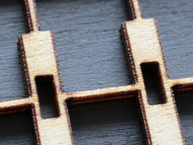
Cut from 1.5mm ply (birch 3 ply). I cut the outside sprues off prior to glueing down since it was not need for strength and would be a pig to remove. I normally paint the ply prior to cutting but wanted to make track fast.

sat2.JPG


I successfully changed the socket width to 1.5mm. This leaves enough meat for strength. I have previously used the shadow of the rail as a sprue and it worked well even with the 1.5mm wide socket.

sat3.JPG


sat5.JPG


sat4.JPG


Martin I am looking forward to sockets appearing within the turnout section. This would be useful even if the chair are WIP. For my prospective sockets on the 2D DXF are all I need.
 

Attachments

  • sat2.JPG
    sat2.JPG
    823.2 KB · Views: 126
_______________
message ref: 2478
Hi TimbersGalore,

Would you mind me asking what laser are you using?

In your pictures shown you appear to have the grain of the ply aligned with the short edge of the sleepers, or are they sanding marks?

Also it would be usefull to know what resin printer, and what resin you are using.

Steve
 
_______________
message ref: 2479
Steve

It is the grain of the birch ply. I was in and hurry and cut it will the grain going across. If it was for real I would have found another sheet with the grain going the other way.

My laser is a "TEN-HIGH" Laser Engraving Cutting Machine 400x300mm 40W CO2 Laser" which I upgraded with the Cohesion3D G code controler. I prepare the files and control the laser using LightBurn. Cutting ply I acheive better than 0.1mm accuracy.
My resin printer is a Phrozen Sonic Mini 4K using 4K resin at 0.030mm layers.
 
_______________
message ref: 2480
Back
Top