Templot Club forums powered for Martin Wynne by XenForo :

TEMPLOT 3D PLUG TRACK - To get up to speed with this experimental project click here.   To watch an introductory video click here.   See the User Guide at Bexhill West.

   Templot5 - To join this open-source project on GitHub click here.  For news of the latest on-going developments click here.  Templot5 is now included with Templot2 - download.        WIKI

  • The Plug Track functions are experimental and still being developed. Some of the earlier pages of this topic are now out-of-date.

    For an updated overview of this project see this topic.   For some practical modelling aspects of using Plug Track see Building 3D Track.

    The assumption is that you have your own machines on which to experiment, or helpful friends with machines. Please do not send Templot files to commercial laser cutting or 3D printing firms while this project is still experimental, because the results are unpredictable and possibly wasteful.

    Some pages of this and other topics include contributions from members who are creating and posting their own CAD designs for 3D printing and laser-cutting. Do not confuse them with Templot's own exported CAD files. All files derived from Templot are © Martin Wynne.
  • The Plug Track functions are experimental and still being developed.

    For an updated overview of this project see this topic.   For some practical modelling aspects of using Plug Track see Building 3D Track.

    The assumption is that you have your own machines on which to experiment, or helpful friends with machines. Please do not send Templot files to commercial laser cutting or 3D printing firms while this project is still experimental, because the results are unpredictable and possibly wasteful.

    Some pages of this and other topics include contributions from members who are creating and posting their own CAD designs for 3D printing and laser-cutting. Do not confuse them with Templot's own exported CAD files. All files derived from Templot are © Martin Wynne.

Getting started with 3D plug track

Quick reply >

Martin Wynne

Admin
Location
West of the Severn UK
Info
.
Enjoy using Templot?
Thanks.

Please do not send requests for help direct to me via email.

Post your questions on the forum where everyone can see them and make
helpful replies.
index.php


With the release of Templot update 241b we have reached a stage where plug track is now a feasible means of building chaired bullhead track. At least for track formations which don't need K-crossings -- single turnouts, crossovers, tandem turnouts. The chairs for K-crossings will come later this year, hopefully.

I've started this separate topic to extract the basics of plug track from the maze of experimental discussions and ideas which have been posted in several other topics over recent months and years. All you need to know to get started is here. :)

The two essential components are:

1. 3D resin-printed chairs, having a chunky tapered plug part below the visible chair base.​
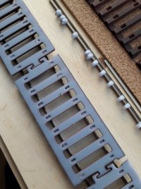
2. a timbering base having rectangular socket cut-outs in each timber, into which the chairs can be plugged.​

or in 7mm/ft scale see COT track below.

This puts each chair in its correct position and rail alignment, and also gauges the rail. No separate track gauge tools are needed when building plug track.

Templot creates the 3D files needed to make these components for any track plan, including complex formations. The 3D files are ready to use, no CAD package or CAD drawing skills are needed. It is however a good idea to have a basic grasp of Templot track-planning before starting the plug track journey.

The timbering base can be 3D FDM (filament) printed, or laser-cut from plywood or card, or CNC-milled into a solid panel, as preferred. The socket sizes can be adjusted so that the chairs will dry clip-fit or press-fit without needing adhesive, or if preferred the sockets can be made a little larger to allow the chairs to be glued in place.

For home track building FDM 3D printing is likely to be the most attractive option. Armed with a resin printer and an FDM printer, material costs are very low compared with other construction methods. Large areas of model trackwork can be constructed for little more than the cost of the rail. The 3D printers will earn their keep from the many other modelling tasks which they can perform.

Plywood timbers are liked for being real wood, but FDM-printed plastic timbers can be given a wood-like surface texture by streaking them with fast-drying typing correction fluid (still used in schools) before painting:

index.php


There are 3 different methodologies for using the plug track components. I'm calling them OPT, FTK and LOJ for easier reference later. They can be mixed and matched as you wish, but it's likely you will come to prefer one of them over the others.


OPT : Original Plug Track

For one-piece chairs having solid outer jaws and keys.

This is the system I had in mind when I obtained a small resin printer (Elegoo Mars 2 Pro) in early 2021, and first started to experiment with this idea. I later coined the term "plug track" to describe it.

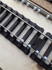
The resin-printed chairs are threaded onto a prepared length of rail, and spaced along it to match the printed paper template. The chaired rail is positioned over the timbering base, and each chair is located loosely in its socket. You then work to and fro along the rail, gradually firming each chair into its socket until all the chairs are fully home. A small block of hardwood makes a suitable tool for this purpose:

index.php


Installing the chairs into the base with the rail already through them makes it possible to fix the rail in place vertically between other existing rails. This makes it possible to build complex track formations which are not possible when rails are threaded horizontally into the chairs from one end. The rail makes a convenient means to apply pressure to the chairs without damaging them. In the latest designs the chairs are an easy clip-fit rather than press-fit.


FTK : Fine Track Kits

For one-piece chairs having solid outer jaws and keys.

This essentially means creating a home-made version of a turnout kit. The chairs are inserted* in the timbering base in advance to create a fully chaired base unit. The rails then slide into place from the ends, in a similar manner to the Finetrax turnout kits.

This does place some restrictions on the track design and prototype details.

Unlike kits available only for fixed sizes and geometry, with plug track you can create your own "kit" for any turnout size from A-4 to F-20, curved onto any radius.

*In 7mm/ft scale you can opt to print the chairs integral with the timbers (COT track) using an FDM printer. This avoids the need for a resin printer. The chair detail won't quite match resin prints, but is on a par with injection-moulded chairs.


LOJ : Loose Outer Jaws


For two-part chairs having separate outer jaws and keys.

In this case the chair is made in two separate parts. The outer jaw and key part is added to the chair after it is fixed in the timbering base, and the rail is standing on it. Adding the outer jaw then clips the rail into the chair.

Many experienced track-builders reading this seemingly crazy idea for the first time might think it madness. At least in 4mm/ft scale. :)

But it has the great advantage that there is no need for the frustrating sore-fingers process of threading chairs onto the rails, or chamfering the rail ends to permit it. Track can be built up in the prototype manner, dropping a prepared rail into the chairs and only then keying it in place in each one.

The loose outer jaw has a long pin below it which locates into a slot in the chair. This makes it quite easy to handle with tweezers. The process is soon learned with a little practice and can be done quite quickly:

index.php


index.php


Not having to slide the chairs along the rail also means that electrical dropper wire connections can be made neatly to the underside of the rail before assembly.


to be continued . . .

Martin.


An introductory video from James Walters:


For the User Guide, go to:

https://85a.uk/bexhillwest/

More information is in the many topics at:

https://85a.uk/templot/club/index.php?forums/plug-track.34/

Practical topics about 3D printers, laser-cutters and building 3D track can be found at:

https://85a.uk/templot/club/index.php?forums/models-methods-and-materials.11/
 
_______________
message ref: 7575
Hi James

Thanks for the excellent video.

Having gone through the process as you described for the chairs and saved the file to my USB stick, I can now see that on the Alkaid printer screen. (Not yet printed anything on my new printer)

I also followed the instructions for sleepers (exporting as a 3D FDM etc fixing the web), I then opened the file in chuitubox, sliced it and saved the file to my USB stick. I can now see the file on the Alkaid printer screen.

Being a complete beginner to 3D printing my question is: can I print the sleepers using my resin printer as against on a FDM printer. It looks like I can, but wanted to get your advise first. (I will eventually look to purchase a FDM 3D printer)
PS: I have made sure that the length of the straight track fits on the plate.

I hope this makes sense and is the correct area on the forum to ask this question.

Any advise appreciated

Stuart
 
_______________
message ref: 8905
Hi Stuart,
I have successfully printed the timber bases on a my Mars 2 zero resin printer, which is equipped along to your Alkaid printer.
But check the bottom of the sockets, as you will have some elephants foot symptom apparent there which can interfere with the insertion Of the chair plugs. It's ok for testing though.
Also check the thickness of the sleepers & compare with the target depth (3.2mm).
Good luck
What resin are you using?
 
_______________
message ref: 8906
Hi Steve, when you printed the timbers with resin, did you lift them off the build plate and add supports or angle the print as you might for a wagon, or did you print flat on the build plate ? Thanks, Tom
 
_______________
message ref: 8907
Underside of some resin timber bases showing elephants foot effect:-
20231107_135827.jpg
Top side of same timbers
20231107_135841.jpg
For the connector clips Martin has provided a solution to the elephants foot by providing a parameter "3-D connector clip bottom offset" , default 0.3mm, which I increased to 0.5mm at Martin's suggestion.
 
_______________
message ref: 8909
Hi Stuart,
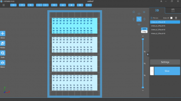
Just to mention that in the video when James imported the chair raft into Chitubox, he then copied it so that there were four copies on the build plate, but a small error crept in to the video, in that he did not "select" all four copies before Slicing.
For example in this shot of 3 chair rafts, only one is selected for slicing
1699370094232.png

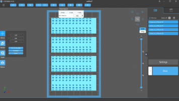
Click on the white square button in left hand window to "select all" giving:-
1699370007319.png
which shows that all four rafts are selected and shown highlighted in blue in list on right.
Then click slice button.
Steve
 
_______________
message ref: 8913
Hi Stuart,
I have successfully printed the timber bases on a my Mars 2 zero resin printer, which is equipped along to your Alkaid printer.
But check the bottom of the sockets, as you will have some elephants foot symptom apparent there which can interfere with the insertion Of the chair plugs. It's ok for testing though.
Also check the thickness of the sleepers & compare with the target depth (3.2mm).
Good luck
What resin are you using?
Hi Steve
Many thanks for the info will have a go at priniting, fingers crossed.

As I purchased the printer from Geeetech thought I would go for their resin as not sure what resin to purchase.

Geeetech Black Standard Resin 1KG, UV 405nm, for LCD/DLP/SLA 3D Printers

Any advise on resin apreciated.

Many thanks
 
_______________
message ref: 8919
I am finding all of this fascinating. I found James' recent superb Youtube video a lovely and unexpected shock. I have occasionally used Templot getting on for 20 years now but had no idea of these 3D printing developments. Martin is a genius to spot the link between Templot and 3D printing and develop his product to take advantage. I also wish him a speedy recovery after his recent fall.

Yesterday I took delivery of an Elegoo Saturn 3 Ultra printer ordered before I saw James' video. I have yet to set it up and get it working but now amazingly, it seems I can print track bases and chairs on it. I did have a question about whether you can print trackbase on a resin printer but some on here seem to have already done it. I understand the "elephant foot" issue but presumably this could be factored in to printer settings. The issue of the various resins is another question I had. I would be inclined towards ABS type resins but perhaps this is the wrong approach. As an O gauge modeller I have purchased checkrail chairs from Shapeways. They are really good but somewhat brittle so you have to be really careful threading rail. So, I would be interested in what type(s) of resin people are using to print trackbase and chairs. With regard to the trackbase printed for O Gauge, I realise I will not be able to print much out in terms of length but do you think some sort of interconnecting mechanism could be used to connect the underlying webs together to form a turnout. My apologies if any of my questions are stupid but this is my first foray into 3D printing.

Regards Les
 
_______________
message ref: 8929
Spent a couple of hours this morning with James’s video. Now I have a timbering base to be printed out in the morning. Will now start looking into a resin printer as well.

Keith
Ps I hope Martin is feeling better and getting home today we all recover better at home.
PPs looking forward to future videos from James on the subject of 3D and Templot
 
_______________
message ref: 8932
Hi Les,
There already is an interconnecting mechanism, but James has postponed describing it as Martin was planning to simplify its use.
The current mechanism is called a connector clip and consists of a tommy bar and claw.
These are currently stored as background shapes but artin has plans to store them as part of the template.

Current method, liable to change
1699463446979.png

Here is a short straight plain template stored as a yellow brick, then control template as been joined on, and the notch is under the peg.
With the colour still yellow, click on shapes menu item to bring up the background shapes window, then clikc on its menu item clip
1699463736333.png


choose add new clip at notch getting:-
1699463804005.png

a tommy bar clip coloured yellow which will associate it with the yellow timbering brick, noting it is called ex-notch brick clip in the background shapes list.
minimise that window and click on the yellow colour box in the Experimental 3D window, and select another colour
1699464015830.png

In this case red, and click ok
then restore the background shapes window that was minimised.
Again select clip menu item
1699464115191.png

and choose add a paired clip
1699464177119.png

Thus giving you the red claw part of the clip that is paired with the yellow tommy bar part of the clip.
If you now store and background the control template, you will now have a yellow brick with a yellow connector clip, and a red brick with a red connector clip.
1699464792263.png

If you now move the control template and join it onto the red template, you will have the the peg and the notch ready for adding the clip at the other end of the red brick etc.
1699464923505.png

Add a new clip at notch to get:-
1699465046985.png


If we then export the red brick we get:-
1699465218200.png


Note that we can improve on this as we do not need the webs at the ends of the brick as they will be in the way when we try and connect the bricks. These can be switched off using the real > shove timbers option and select each of the two end timbers and switch off the web.
1699465461310.png

In this case timber A1 has TS-flange and MS-flange unticked as has the A9 timber, giving:-
1699465602211.png


This example is just to show that connector clips already exist, and can be used.
Hope this helps
Steve
 
_______________
message ref: 8934
For Resin Printing chairs the current flavour of the month is:-

Anycubic ABS-like V2 water washable resin.

The important bit being V2 as it is water washable.

Make sure it has V2 on the label and is advertised as water washable.
Steve
 
_______________
message ref: 8951
For Resin Printing chairs the current flavour of the month is:-

Anycubic ABS-like V2 water washable resin.

The important bit being V2 as it is water washable.

Make sure it has V2 on the label and is advertised as water washable.
Steve
Hi Steve
Many thanks
Stuart
 
_______________
message ref: 8954
Hi Stuart,
I have successfully printed the timber bases on a my Mars 2 zero resin printer, which is equipped along to your Alkaid printer.
But check the bottom of the sockets, as you will have some elephants foot symptom apparent there which can interfere with the insertion Of the chair plugs. It's ok for testing though.
Also check the thickness of the sleepers & compare with the target depth (3.2mm).
Good luck
What resin are you using?
Hi Steve, quick question. Do You know if there is a way to resin print timbers complete with loose jaw chairs? I have both resin (Form3) and FDM (AnyCubic Kobra+) but I'm just not getting consistent quality FDM timber results I want.
 
_______________
message ref: 8983
Well here’s one for the head scratchers. After following Jameses video I quickly got to the point of printing out a test panel.

IMG_2704.jpeg

Now this to me with my printer set up seamed a bit strange so say the least. It was all done on my laptop and printed on my Ender 3 pro. I have the latest version of Templot I use pursa slicer. Also it took me a long time to find 3D builder that was installed. In fact Templot would not load 3D builder so I had to do it manually. I also downloaded the latest version of Cura and sliced with that and as you can see I added a brim.For my printer I always use a brim as it gives good adhesion. So a couple of trial prints but still with the same results. Then just as a test I did the following. I have a second laptop the pervebable used by a little old lady to go to chapel ever Sunday. In fact it was my 94year old mother’s machine which she managed to lose the touchpad drivers. I inherited it…… So I load Templot made sure 3D builder was installed and download Cura. I then did a new file of a track panel and now Templot opened 3D builder and I sliced in Cura. Off to print not thinking anything will change but below is the latest print.

No idea what happened on my laptop but maybe I have to use my spare computer just for Templot.

Keith

IMG_2705.jpeg
 
_______________
message ref: 8986
Well here’s one for the head scratchers. After following Jameses video I quickly got to the point of printing out a test panel.

View attachment 7710
Now this to me with my printer set up seamed a bit strange so say the least. It was all done on my laptop and printed on my Ender 3 pro. I have the latest version of Templot I use pursa slicer. Also it took me a long time to find 3D builder that was installed. In fact Templot would not load 3D builder so I had to do it manually. I also downloaded the latest version of Cura and sliced with that and as you can see I added a brim.For my printer I always use a brim as it gives good adhesion. So a couple of trial prints but still with the same results. Then just as a test I did the following. I have a second laptop the pervebable used by a little old lady to go to chapel ever Sunday. In fact it was my 94year old mother’s machine which she managed to lose the touchpad drivers. I inherited it…… So I load Templot made sure 3D builder was installed and download Cura. I then did a new file of a track panel and now Templot opened 3D builder and I sliced in Cura. Off to print not thinking anything will change but below is the latest print.

No idea what happened on my laptop but maybe I have to use my spare computer just for Templot.

Keith

View attachment 7711
Hi Keith
I saw the same issue with Cura missing the sockets on the track panel when I didn't get the 'repairing the .STL' stage completed properly. Once I got the .STL repaired it worked fine.
David
 
_______________
message ref: 8989
Hi Terry
Yes there is! Martin has catered for everything.
However you will get problems with uncured resin, blocking the bottom of the loose jaw slots, unless you print the timbers on supports. There is an option for that but I am away from PC at present.
You might be better off printing resin timber bases, then printing loose jaw chairs an jaws on a raft and use them as Martin intended.
when the chairs are printed on supports on a raft their is a drain hole under every slot
Steve
 
_______________
message ref: 8991
Hi Steve, quick question. Do You know if there is a way to resin print timbers complete with loose jaw chairs? I have both resin (Form3) and FDM (AnyCubic Kobra+) but I'm just not getting consistent quality FDM timber results I want.
@Terry Downes @James Walters

as i feared, folks are jumpimg ahead of me.

the design intent is that the timbering base is fdm printed, or laser-cut, or cnc milled.

not resin printed. that is not to say it can't be done, but it needs to be done by someone who is well experienced in resin printing. also i have not done any such thing myself and i am completely unable to provide any advice or guidance. there will be problems with shrinkage, warping and curling which may get worse over time. it may be difficult to get an accurate gauge.

if you print the chairs with loose jaws slots integral with resin timbers there will be significant problems in washing the resin from the tiny slots for the loose jaws, due to elephant's foot on the bottom. the timbers can be raised on the bed of nails rafts to help with washing, but that function is completely untested and it may be difficult to remove the timbers from the nails. whatever else you do, make sure you use a resilient resin such as the ABS-like resins and not the bog-standard brittle resins.

generally i would advise to get an fdm printer instead for the timbering. that was always the default design intent.

however, it will be difficult to get good fdm results for the timbering with any of the standard profiles supplied with typical fdm printers. the intention is that you create a custom profile for the purpose, or create a custom printer in cura which will accept my own .curaprofile file. to get consistent Z levels across repeated prints i recommend that you ignore the usual paper-levelling methods and set the levels by measuring the thickness of extruded filament.

i intended to take everyone through all this before they jump too far ahead but because of my injury i'm unable to do so at present. in fact it is causing me agony to type this and i need to stop. i shall have to provide more info via zoom meetings only. i'm sorry.

martin.
 
_______________
message ref: 8994
To add to Martin's notes above, I've experimented quite a bit with resin printed timbers, including using some exotic resin mixes to try and eliminate the inherent shortcomings of resin printing the timbers. I've also tried printing on a raised supports to mitigate the elephants foot and resin clearing issues. I think I've experimented with just about every conceivable variable and drawn a firm conclusion.

My conclusion was that it wasn't a suitable approach. The biggest problem, which doesn't always immediately show itself, it that the timbering will curl. And the power with which the curling occurs can be quite surprising, especially if longer lengths are laid in one piece.
The parts will lift themselves and bend the rails if fitted. Even glued-down timbering bases will curl, and if the glued bond doesn't break, then the part will fracture, lift and leave the bottom surface glued.
By all means experiment, I certainly learnt a lot by doing so, but I think this is without doubt the wrong solution for a long term layout project.

The as-designed-for FDM bases work well long term, as do laser-cut bases.
If one only has a resin printer, then I'd say go-ahead and experiment, if only to learn the Templot process, but ultimately you will be looking for access to an FDM printer to get the best results.

I would hate for folks to become disappointed with the concept through applying it incorrectly.

I should add that my experiments were conducted on a home-grade resin printer. I'm certain that with something like a true SLS printer and £160/litre resins the results would be superb, but again, I don't think access to such technology is part of Martin's design intent. But could of course be an option for those wishing to have their parts commercially printed, albeit a very expensive process.
 
_______________
message ref: 9001
@James Walters

hi james,

many thanks for that. i was sure folks were going the wrong way with resin timbers, but i didn't have much practical evidence to confirm it. you have obviously done lots of trials and arrived at the same conclusion. thanks.

resin-printed bases are clearly possible, because wayne kinney uses them in his finetrax kits. but i imagine he is using industrial-grade printers, and i remember him saying that he has his own secret resin mix for them.

cheers,

martin.
 
_______________
message ref: 9003
I can confirm that sleepers printed in resin in 7mm scale curl beautifully whilst curing!

They looked very nice for about 3 minutes but are now only suitable for a roller coaster 🙂

Davey
 
_______________
message ref: 9004
Thanks for sharing all your experiences and suggestions. I have been playing with resin timbers for several months now with varying degrees of success. I confess that I have probably not left any resin printed timbers/bricks stuck down for any length of time to determine suitability for layouts etc. So, I really want to get my FDM prints up to scratch. I’m currently playing with the Cura settings and found that the Ironing function helps with cleaning the top layer but, I’m not happy with the blobs at the timber corners and either side of the plug holes. Any Cura profiles or settings advise would be appreciated but, I think I have probably incorporated most previously suggested settings/info but, I’m open to more!
 
_______________
message ref: 9005
A follow up to my missive yesterday. This morning I went to lap 2 and produced a trial curved section that went to print and came out fine. So I thought about what had happened and decided to see what could be done. As I had downloaded the latest version of Cura and checked on 3D builder. So I wondered if maybe Templot was the issue. I uninstalled Templot and reinstalled and then tried a test piece. It seams I have cured the problem.

IMG_2707.jpeg


A happy man now just need to either get a resin printer or find someone who has one.

Keith
 
_______________
message ref: 9007
Thank you James, that is extremely helpful reinforcement of Martin's previous "hunch", and timely for me as I was about to try some resin bases having only a resin printer.
However, I will hold off.

The only parts of my current layout that are ballasted so far are Wayne's British Finetracks printed turnouts, as he advises gluing down.
Those do hold flat fine once glued incidentally.
But they are thinner than the plug track design, so perhaps easier for the glue bond to hold down.

I am currently enjoying the topic on CNC milled bases and as I don't have access to an FDM printer that seems like an interesting option instead.
 
_______________
message ref: 9009
Last edited:
Good morning
Many thanks for all the posts and James & Martin for the clarification regarding 3D Resin & 3D FDM printing for chairs and sleepers.

I have now purchase the ANYCUBIC Kobra 2 Neo FDM 3D Printer for printing the sleepers.

Please can I have some advise on which filiment to purchase for the FDM printer to print sleepers. I am working in 'OO' gauge if that makes any difference.

Apologies if this has already been covered as I may have missed it.

Many thanks
 
_______________
message ref: 9271
Good morning
Many thanks for all the posts and James & Martin for the clarification regarding 3D Resin & 3D FDM printing for chairs and sleepers.

I have now purchase the ANYCUBIC Kobra 2 Neo FDM 3D Printer for printing the sleepers.

Please can I have some advise on which filiment to purchase for the FDM printer to print sleepers. I am working in 'OO' gauge if that makes any difference.

Apologies if this has already been covered as I may have missed it.

Many thanks
@Stuart

Hi Stuart,

The filament I'm using is this, in grey or brown:

https://www.amazon.co.uk/gp/product/B07FQKP7NS

https://www.amazon.co.uk/gp/product/B07FQ75QG2

it's toughened PLA-PLUS which is more resilient than standard PLA. The same filament for both the timbering bases and the filing jigs.

Other brands of toughened PLA-PLUS should work equally well.

cheers,

Martin.
 
_______________
message ref: 9272
Hi Guys,
At last some progress with a low cost laser (10W output) cut timbers resin chairs and loose jaws on all but the end two chairs (ease of holding the rail down) whilst insetting the loose jaws.
Martin, would it be possible (easy I mean) to have separate kerf offset values for the timber sand the chair sockets?


2.6 mm ply.jpg


top is 0.15 kerf btm is 0.2 kerf.jpg


with chairs and rails fitted.jpg


I know in theory that should not be required, but on low power lasers it loos as though the chair socket burns hotter, than the timber outlines so they are different. It would be hugely beneficial if two independent kerf values were an option.
If not don't worry for now, I can still do it. I just have to make two DXF files and then glue them back together in a cad package.
cheers
Phil.
 
_______________
message ref: 9273
Martin, would it be possible (easy I mean) to have separate kerf offset values for the timber sand the chair sockets?
@Phil G @James Walters

Hi Phil,

Ok, I can do that. Do others agree?

In the meantime there is no need for a separate DXF. You can kludge the same effect by changing the socket size:


socket_size_adjust.png


Change the first 3 settings on that button by whatever difference you want. i.e. the difference in kerf setting required.

Don't change the other settings on that button. Use the other buttons if you are preferring the other fit options.

Martin.
 
_______________
message ref: 9274
Hi Phil & Martin,
Before Martin introduced the kerf parameter I used the socket size parameter to alter the socket as described by Martin above, so that should work for you now.
Can you confirm that you are cutting the KERFSOCK layer first, before then cutting the KERFTIMB layer, as that will make a difference to the accuracy of the sockets.

Also, instead if using fixed jaw chairs on the ends, try using a cocktail stick inserted in the chair slots of the ebd chairs to hold rail whilst inserting the loose jaws.
Steve
 
_______________
message ref: 9275
.
This topic was intended to be an extract of the basics from the other topics to get beginners started.

It has now gone completely astray, just like all the others.

Martin.
 
_______________
message ref: 9276
_______________
message ref: 9293
Can you confirm that you are cutting the KERFSOCK layer first, before then cutting the KERFTIMB layer, as that will make a difference to the accuracy of the sockets.
Hi Steve,
yes that's correct, text first and then all sockets next, and then the timber outline last. Just got a C12 crossover on the machine now. That's big jump up from a 100 x 100 test piece. Not sure it will work first time, as there a lot of snibs adjustments required for a crossover.
Only one way to gain knowledge though, still very much a beginner to laser cutting.

I tried the cocktail stick trick and found I prefer to use solid chairs at each end, in some respects only two solid chairs per rail length is actually easier then fitting the loose jaws.
cheers
Phil,
 
_______________
message ref: 9294
Hi Martin

Hope you are fully recovered.

Many thanks

Stuart
@Stuart

Hi Stuart,

Unfortunately not. Current timeline is 3 months to get normal use of my arm, 4-5 months before it's strong enough to drive again. So far it is 3 weeks, so still a long way to go.

Thanks for your kind thoughts.

Martin.
 
_______________
message ref: 9296
If anyone is looking for a cheapish FDM printer, then you can get an Elegoo Neptune 3 Pro, direct from Elegoo for $199, which works out at £157.55.
That works out at 20x 32ft track panels if they were printed in SLS with a print bureau (not that sls is recommended but gives a ball park price).
Having bought a laser cutter last month I did try and resist, but the functionality of the FDM timbering bases was too hard to resist.
 
_______________
message ref: 9300
Back
Top