Templot Club forums powered for Martin Wynne by XenForo :

TEMPLOT 3D PLUG TRACK - To get up to speed with this experimental project click here.   To watch an introductory video click here.   See the User Guide at Bexhill West.

     Templot5 - To join this open-source project on GitHub click here.  For news of the latest on-going developments click here.  Templot5 is now included with Templot2 - download.

  • The Plug Track functions are experimental and still being developed. Some of the earlier pages of this topic are now out-of-date.

    For an updated overview of this project see this topic.   For some practical modelling aspects of using Plug Track see Building 3D Track.

    The assumption is that you have your own machines on which to experiment, or helpful friends with machines. Please do not send Templot files to commercial laser cutting or 3D printing firms while this project is still experimental, because the results are unpredictable and possibly wasteful.

    Some pages of this and other topics include contributions from members who are creating and posting their own CAD designs for 3D printing and laser-cutting. Do not confuse them with Templot's own exported CAD files. All files derived from Templot are © Martin Wynne.
  • The Plug Track functions are experimental and still being developed.

    For an updated overview of this project see this topic.   For some practical modelling aspects of using Plug Track see Building 3D Track.

    The assumption is that you have your own machines on which to experiment, or helpful friends with machines. Please do not send Templot files to commercial laser cutting or 3D printing firms while this project is still experimental, because the results are unpredictable and possibly wasteful.

    Some pages of this and other topics include contributions from members who are creating and posting their own CAD designs for 3D printing and laser-cutting. Do not confuse them with Templot's own exported CAD files. All files derived from Templot are © Martin Wynne.

Loose jaw plug track - rail inclined inwards?

Quick reply >

Gt.shefford

Member
Location
Hampshire
As a long time Templot bodger I fancied having a go at making a lenght of Plug track as a prelude to using it on my layout.

After watching (and re watching) James' excellent videos I managed to produce this length of P4 track

P1.jpg


However when viewed end on...

P2.jpg


the rail in inclined inwards. As far as i can tell the chairs and jaws are seated fully leaving me to suspect that the rail causing the inward cant (curiously the track is to gauge). The rail is current production C&L steel rail. The sleepers are 3mm poplar (the same material used by C&L for their 7mm sleepers), the chars are printed in Elegoo ABS-like 2.0 resin.

Any thoughts on possible setting changes to dial out this inward cant?

Jonathan

p.s

I should say that before making this test piece I spent an evening creating a chaired 3-way (start with an easy one?)

P3.jpg
 
_______________
message ref: 11592
Hi Steve,

Loose jaws, and used all the defaults settings (selected C&L/EMGS/S4 code 75 rail)

Jonathan
 
_______________
message ref: 11594
@Gt.shefford

Hi Jonathan,

Welcome to Templot Club. :)

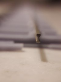
Well done on making your first piece of plug track.

Any thoughts on possible setting changes to dial out this inward cant?

This is where you are jumping ahead of me on what is still a very experimental project. I do have several thoughts on the subject, but which of them would be correct needs me to handle the track and get a feel for what's happening.

Writing a proper reply to your question is going to take me an entire evening or even a whole day. This is why this project is getting too much for me -- the endless explaining needed is more than I can manage.

There is a whole User Manual to be written on using plug track and getting the best results from it. But that requires a lot more progress with the programming, and then a long period of trial and testing, and reports from users. The results I get here with my own printers are generally good, and I use the settings as the defaults in the program. But every time I release a program update I have usually made a tweak here or there in some of the dimensions. Whether others are getting the same results from their machines I have no way of knowing.

The first question to ask about the non-upright rail is how firmly is it held between the key on the outer jaw and the grip part of the inner jaw? If there is any significant sideplay, the chairs need tightening up a little. There are at least 3 possible ways of doing that:

1. increase the exposure time in the printer. The need for that can be discovered by measuring some known part of the chair. Bear in mind that it will also make the loose jaw pin fit closer in its slot, so don't do it if there is no detectable play there.

2. reduce the web thickness setting in the rail section dimensions, or use the tweaking adjustment box on the rail tab.

On the other hand if the rail is a tight fit in the chair, it probably needs easing a little. Not least because that might lead to stress-cracking of the chair over time.

3. change the fish angle and fish intersection dimensions for a better fit to your rail. Also if the rail-foot is wider than the rail-head, make sure this is reflected in the custom chair settings.

One reason for open-sourcing the code recently is so that folks can see what's happening and possibly suggest where I can make improvements. The default EMGS rail section dimensions in the program have been taken from some 10-year-old nickel-silver rail from the EMGS. How well this matches current steel rail from C&L I have no way of knowing. The dimensions can be seen in dxf_unit.pas and here they are:

Code:
      // model rail section over-rides ...

      // C&L / EMGS / Exactoscale code75 bullhead. including some 3D printing allowances ...

    if dxf_form.emgs_75_rail_radiobutton.Checked=True
       then begin

              rail_section_option:=1;

                 // convert to full-size at 4mm/ft and back to current scale   (4mm/ft = *3" per mm)

              rail_depth_mm:=1.90*3*inscale;   // code 75 // - 2D TEMPLATE SETTING MAY DIFFER  (cpi.rail_height_pi - inclined rail calcs - in inches)

              rail_head_width_mm:=0.90*3*inscale;   // - 2D TEMPLATE SETTING MAY DIFFER  (cpi.railtop_pi - in mm)

              rail_corner_rad_mm:=0.15*3*inscale;

              rail_foot_width_mm:=0.90*3*inscale;

              rail_fish_angle:=1.5;          // 1:n   arbitrary

              rail_web_top_mm:=0.80*3*inscale;        //  from rail top to intersection fish angle on rail centre-line
              rail_web_bottom_mm:=1.25*3*inscale;     //  from rail top to intersection fish angle on rail centre-line

              rail_web_thick_mm:=0.35*3*inscale;

              fish_calcs;
            end;

If you can bear with me I will write again in a day or two.

cheers,

Martin.
 
_______________
message ref: 11595
Evening Martin,

Thank you for the informative reply.

The layer exposure is 3s, on a 0.02 layer (using a photon Mono) - I have a Saturn 3 ultra which is still in its box

The rail is 'tight' in the chairs - there is no lateral movement. All the jaws slotted in with minimal force, except 2 which were considerably tighter (suspect I didn't clean the socket well enough and the hole ended up under size once cured.

I am happy to experiment with the rail settings and see if I can make the rail more vertical. The diagram in the N Gauge plug track thread will be helpful in working out which values to change (https://85a.uk/templot/club/index.php?threads/n-gauge-plug-track.781/post-10385)

Jonathan
 
_______________
message ref: 11596
@Gt.shefford

Hi Jonathan,

Thanks for finding the diagram for me:

index.php


If the rail is tight in the chair and not upright, I suspect the key is too high and pushing it over. Try increasing dimension F above.

Note when using the custom rail button you will need to change most of the settings because the starting dimensions shown are the exact prototype dimensions. One job on my to-do list is to make them start from the current model setting.

cheers,

Martin.
 
_______________
message ref: 11597
Hi Jonathan,
Do you have any alternative rail by any chance?

I have been using P4 society nickel silver rail.
Also used 0.05 layer thickness, and more especially with anti-aliasing switched off, ABS LIKE IPA washable v1 resin on Elegoo Mars 2 pro.
Steve
 
_______________
message ref: 11598
Thank you for posting those photos Steve, and your suggestion re different rail.

Comparing my printed keys with those in your photos, there appears to be a size difference, however before altering any presets in templot I'll make-up a new test piece, using some HiNi instead.

Re AA, Photon Workshop doesn't explicitly say it's turned off, instead it has a drop down list giving a range 1,2,4,8 (I believe a value of 1 means its off)

Janathan
 
_______________
message ref: 11605
Hi Jonathan,
Assuming you are printing a raft which you have defined in templot as a backgound shape of a specific size, then after printing, washing, drying and curing etc. measure the dimensions of the raft and check how close they are to the size specified in Templot to check shrinkage.

As you are using ply timbers I assume you are printing press-fit chairs?

Having plugged the chairs into the timbers, test the fit of the rail against the inner jaws. It should just sit in nice and vertical and be capable of being held their by inserting a pair of cocktail sticks into a jaw slot at each end of your test piece.

Then as you insert a loose jaw elsewhere, there is a final satisfying little click as the key moves past the rail head and nestles into the web as the jaw part seats home.

Another test you can perform is print a raft of fixed jaw S1 chairs, and with them still on the raft try sliding a piece of rail into them, having champered the end.

If all else fails perhaps you could send Martin a small offcut of your rail for him to check against his chairs?

Perhaps there ought to be a law that all rail manufacturers submit samples to Martin :)

Steve
 
_______________
message ref: 11607
_______________
message ref: 11608
I have just set another batch printing, so when they finish I'll run the vernier over them to make sure they correlate

As a quick and dirty check I overlaid the two .stl's in Rhino and added the just the rail web (the C&L steel rail's web is 0.38mm) and it is apparent that the inner face of the key collides with the web by 0.082mm (this is consistent with both the raw and fixed files - I did wonder if the online STL repair sites algorithm was the cause.


P4.jpg


Is there and substantial difference between the clip-fit and press-fit, other than the void in the plug to allow the tangs to deflect?

My preference is to used ply sleepers, partly for the appearance, but also as I manufacture sleepers for C&L I have a ton of Finnish Birch off-cuts that I'm keen to use up.

Jonathan
 
_______________
message ref: 11609
Is there and substantial difference between the clip-fit and press-fit, other than the void in the plug to allow the tangs to deflect?
@Gt.shefford

Hi Jonathan,

The press-fit plugs do not have side tangs. They are a tighter press fit in the sockets, relying on an interference fit to retain them, rather than side tangs.

However, James has reported that the clip-fit plugs work fine in his plywood. Different types of plywood may vary in this regard.

For trial and error changes to the rail fit in the chairs, use this box:


rail_fit1.png


This changes the chair space for the rail web in +/- percentage terms. i.e. +10% would increase the space from 0.35mm to 0.385mm for a looser fit. -6% would reduce it to 0.329mm for a tighter fit. (Do not enter the % character.)

A small change may be enough to make a difference.

Martin.
 
_______________
message ref: 11612
My HINi is also 0.3mm, so looks like the steel rail is the cause.

I've just modelled the 0.3 web in Rhino and it looks much better

P5.jpg

I also measured the raft from my original print with the following results

X - 20.58mm actual, 20.56mm Slicer
Y - 84.51mm actual, 84.60mm Slicer

Te next batch of chairs should be finishing shortly so I'll report back soon.

Jonathan
 
_______________
message ref: 11613
Just put together the second test piece (had a higher attrition rate of jaws lost to the carpet monster this time), and even with the HiNi I am still getting an inward cant.
PXL_20240615_120025419.jpg

PXL_20240615_120318356.jpg


I'll try adding a few % to the rail fit and see if that improves things.

Jonathan
 
_______________
message ref: 11615
@Gt.shefford

Hi Jonathan,

It's difficult to see from your photos, but the top of the key looks too high. Can you detect the key clipping snugly into place below the rail-head as you push it down?

The problem may be related to:

The layer exposure is 3s, on a 0.02 layer

Which seems excessive to me. The snag being that I know nothing about your printer.

I am using 2.2 seconds for 0.05mm layers on the Mars2+ and Alkaid printers. On that basis 0.02mm layers would need only 0.88 seconds per layer. 3 seconds would be too much.

I suggest trying 0.05mm layers with say 2.5 seconds per layer. Unless your printer is an old one with much lower UV lamp power.

cheers,

Martin.
 
_______________
message ref: 11617
Jonathan, Martin,

I've had the same problem and came to the conclusion that over exposure is part of the problem. I used 2.1s with 0.05mm layers on a Mars 4 9k. I'm currently using the Resin XP2 Vlidation Matrix to refine the exposure time, but being a typical English summer rain has stopped play.

The other part of the problem is that my S4 society nickel silver rail dimension E is 0.36mm. How do you measure dims F & G?

Another thing I noticed which might be caused by over exposure is that one row of chairs had under sized slots that didn't allow the loose jaws to fully go home. In the photo below the slots in the top row of chairs on the upper raft are under size. It was a repeat print at 2.1s. The lower raft was 1.9s and they look better; both rafts are the same way around on the print bed.


IMG_E2869.JPG


I'm sure it's not related to cleaning the chairs as after I plunge in to a bucket of water several times I use a water jet from a garden sprayer: https://www.ebay.co.uk/itm/225917761883?var=525007188555

It will probably be Monday before I settle on a final exposure time and I'll try to remember to tell you what I end up using.

Thanks
Richard
 
_______________
message ref: 11618
The more I think about it I am leaning (sorry - no pun intended) towards the printer settings. The latest panel still leans inwards having applied a 10% rail fit.

On some chairs, and mainly those on the same side (further leads me to suspect printer setting per Richards photo) I can feel a nice positive engagement,

I'll run a few more rafts with different layer heights/exposure times and report back

Jonathan
 
_______________
message ref: 11619
Jonathan, Martin,

I've had the same problem and came to the conclusion that over exposure is part of the problem. I used 2.1s with 0.05mm layers on a Mars 4 9k. I'm currently using the Resin XP2 Vlidation Matrix to refine the exposure time, but being a typical English summer rain has stopped play.

The other part of the problem is that my S4 society nickel silver rail dimension E is 0.36mm. How do you measure dims F & G?

Another thing I noticed which might be caused by over exposure is that one row of chairs had under sized slots that didn't allow the loose jaws to fully go home. In the photo below the slots in the top row of chairs on the upper raft are under size. It was a repeat print at 2.1s. The lower raft was 1.9s and they look better; both rafts are the same way around on the print bed.


View attachment 9845

I'm sure it's not related to cleaning the chairs as after I plunge in to a bucket of water several times I use a water jet from a garden sprayer: https://www.ebay.co.uk/itm/225917761883?var=525007188555

It will probably be Monday before I settle on a final exposure time and I'll try to remember to tell you what I end up using.

Thanks
Richard
@Penrhos1920

Hi Richard,

Thanks for that. The upper raft definitely looks over-exposed with rounded corners in the pin slots. The lower raft looks much better and crisper. Although I know how infuriatingly difficult it is to photograph the resin close-up. Have you tried going down a bit more, to say 1.75 seconds?

Dimensions F and G are difficult to measure without a microscope. It is dimensioned that way in Templot to match the prototype dimensioning. The fishing centres are important to ensure the fishplates work as intended. The critical dimension being the fish angle.

If you can't determine otherwise, the dimensions in 4mm scale for typical model rail are:

Enter the fish angle as 1.5

For F, measure the side of the rail-head and add on 0.3mm. The result might be around 0.8mm.

For G, measure the side of the rail-foot and add on 0.3mm. The result might be around 0.65mm.

Remember to measure both sides of the rail, and average the results.

Make a clean square end on a bit of rail (touch it against the sanding disc). Make a test chair print, and slide it just onto the end of the rail. With a magnifying glass, examine the fit of the key against the rail. Adjust F and G and maybe the fish angle as seems to be necessary. Repeat until happy. Make a note of your results for use next time.

cheers,

Martin.
 
_______________
message ref: 11620
Some success (I think)

By changing the printer setting (layer height 0.05, exposure 2.5s) the loose jay now slides smoothly (with just light finger pressure) into the slot, with a nice, just perceivable 'clunk' as the key passes the lower face of the rail head and locates in the web. I was also able to extract and reset the jaws when I noticed I'd initially put the rail in upside down.

P9.jpg


As an additional check i printed a raft of full chairs, and the rail slid in nicely (with a minimal amount of wiggling) On the above photo the full chairs are on the rear rail.

P8.jpg

Rail end on in the full chair


P7.jpg

Rail end on in the loose jaw chair

In both images I think the inner face of the key still pushing the head inwards, so maybe I try a raft with 10% rail fill

Jonathan
 
_______________
message ref: 11622
Another test you can perform is print a raft of fixed jaw S1 chairs, and with them still on the raft try sliding a piece of rail into them, having champered the end.

Hi Guys,
Just as a though and to save a huge amount of correspondence, I wonder if the best approach for first time user is to recommend a small trial batch of fixed jaw type S1 chairs are made first?.
The logic would be twofold,
Firstly this small batch of chairs can be used as a sort of go, no go gauge for your chosen rail, i.e. it can be used to test the rail to chair clearance and rail settings, going a bit further once your happy with the rail fit, it can also check for the chair to sleeper fit. Once your happy that everything is working out correctly then switching to loose jaws becomes a safer bet.

Secondly to all intents and purposes, thats is exactly how plug track evolved. So by default the first versions of plug track were made using fixed jaw chairs and confirming the fit was as required, and only then moving onto loose jaws, as that option evolved.

Thus by replicating the original process a lot of vital info can be gained very early on, including things like correct printer settings relevant to both the make of your printer and the interaction of that printer with the type of resin you are using. So suiting your application.

You could argue by doing this with the fixed jaw chairs first you are waste time, I would argue the learnings you get from going down this path pay very quick benefits both in term's of fault finding and an easier less stressful initial leaning curve.

One final though just because its called "PLUG TRACK" most certainly does not mean this system will ever be a simple plug and play solution.
After all there are so many variables that are outside the initial control of the software, that will always be the case. It's the very reason there are so many options available when setting up your process.
This will also apply even after it moves from and experimental project to whatever its called next.
cheers
Phil,
 
_______________
message ref: 11623
On the subject of resin printer best exposure time, in relation to layer height
I think we would be wise to take a leaf for the war gaming fraternity book, as I believe they have been using 3D resin printers longer than most railway related applications.
On a lot of there posts, they go chapter and verse about resin type, resin temp, machine type (strength of UV source) all interact with exposure time therefore exposure time is the single most critical thing about resin printing.
overwhelmingly the recommendation for setting the printer up, is to use the cones of calibration by table forge.
zip of the cones attached. if you YouTube cones of calibration there are some good videos on how to use it.

The idea of the cones is on the pass side, you should have fully formed cones which do just meet in the middle. On the failure side they should not quite meet. you adjust your machine in terms of layer height and exposure time, by doing a first best guess (manufactures recommendation) and then looking at the result you get and reading the instructions on setting changes using the cones.
Basically When you get the correct result, your machine is calibrated your good to start printing, chairs for example.

Some of the war games guys go as far as to say any major change, IE new bottle of resin or even a seasonal temp change should trigger a recheck with the cones, that is if you want to keep everything exactly as required.
@Martin W, I will post the cones of calibration in the resource section of the site as well.
cheers
Phil,
.
 

Attachments

  • The Cones of Calibration - 5416700.zip
    2.9 MB · Views: 91
_______________
message ref: 11624
Afternoon,

first time user is to recommend a small trial batch of fixed jaw type S1 chairs are made first?.
this small batch of chairs can be used as a sort of go, no go gauge for your chosen rail
Knowing what I know now I would wholeheartedly endorse this route.

I will run the 'cones of calibration' file and see how it looks.

By way of bringing this thread full circle I reassembled an earlier panel with the new chairs, reusing the steel rail with the result below

PXL_20240616_154709052.jpg


There is the slightest hint of inward cant, but perhaps more importantly a pair of roller gauges drop on nicely with no manipulation.

Jonathan
 
_______________
message ref: 11633
There is the slightest hint of inward cant

Hi Johnathan,
if your inward cant is close to 1 in 20 your ahead of the game, :) not exactly sure how thats going to work when you get to doing turnouts though, The hard part of inclined rails is very much the complicated bend required at the knuckle.
I am in no way seriously suggesting we should have inclined rails for plug track..
cheers
 
_______________
message ref: 11642
I've reduced the exposure to 1.7s and reprinted; I included some fixed jaw S1 chairs. The result is that the rail doesn't slide into the fixed jaws and they are inclined in the loose jaws.

IMG_E2872.JPG

2.1s, 1.9s, 1.7s (loose & fixed jaw)

I print along the bed. Does the orientation make a difference?

Orientation.jpg


IMG_2874.JPG


To me it looks like the rail is not fitting under the fixed jaw and the top of the key needs lowering. I assume it's best not to change these dimensions until the exposure is sorted?

Off to try 1.5s exposure with the cones of hell added just for fun!
 
_______________
message ref: 11658
I print along the bed. Does the orientation make a difference?
@Penrhos1920

Hi Richard,

I print with the chair rafts across the width of the build plate. i.e. 90 degrees to your photo. I have found that it does make a slight difference on the Mars2 Pro.

I imagine that this is very printer-specific, so impossible to advise for any other printer. More trial and error needed. :)

It seems that in addition to the quick-tweak box for the web thickness, we perhaps need the same for dimensions F and G in the rail section. I will look into that.

p.s. your rail section may not be symmetrical -- what happens if you swap the rail end-for-end?

cheers,

Martin.
 
_______________
message ref: 11659
From right to left

PXL_20240618_133401316.jpg


2.5s, 2.0s,1.8s,1.7s

I tried 1.5s but this had failures on the 'success' side, so I'll try a 1.6s.

Jonathan
 
_______________
message ref: 11660
I hadn't thought of where the failure bit end up. There weren't any 'failed' bits stuck to the FEP, however looking at the design of the test piece I guess the failures would be captured/enveloped by the underside of the top flange.

Jonathan
 
_______________
message ref: 11663
Hi Jonathan,
I think you are being bit to literal on the failure side, the good side is just fully formed cones and the failure can be not quite fully formed cones. You have to look at both sides to make the correct determination. I found about 2 second is more or less right for me on my mars 3 pro with Elegoo resin, but then if you start to change the temp of the resin you very quickly see the cones change and I mean by only a few degrees certainly more than 5 degrees and you can see it having an effect.. Hotter resin needs less cure time. As to the fail you don't get floating chunks as such, you simply get not fully formed cones. I guess there has to be some micro particles of cured resin floating around in the resin solution (however on reflection thats a likely cause for the resin starting to get a bit thicker overtime. can I ask are you stirring your resin every day?
cheers
Phil,
 
_______________
message ref: 11667
Hi Jonathan,
looking again at your failure side, and assuming for the 2 second test in the photo your good side is ok (still fully formed cones) I would say your also close to a 2 second exposure time. Maybe 1.9 if the good side is still fully formed. once you have it dialed in try changing the temp by a few degrees you will see it has a very noticeable effect. You can actually work this test backwards to see what sort of temp range you have once the ideal exposure time has been established.
cheers
Phil,
 
_______________
message ref: 11668
Morning Phil,

If I've left resin sitting the the vat overnight I'll give it a gentle stir at the start of a printing session - I never leave the vat in the machine overnight, but remove it and cover the open side and FEP with the molded silicone covers that were supplied with the vat.

I've never paid much attention to the temperature and how that impacts the prints. My printer sits on the bench in a heated workshop - its actually next to the thermostat which is currently set to 20 degrees C. If I'm doing a production run (last week I was running off 20 build plates worth of the same part) the aluminium vat is actually quite warm - maybe 25/27 degrees C.

With the exception of the1.5s, all the calibration cones printed fully on the 'success' side. I am inclined to try a raft of S1's at 1.8s (both loose and fixed jaws) and compare it to the 2.5s I tried earlier.

Jonathan
 
_______________
message ref: 11676
Hi Guys,
Just as a though and to save a huge amount of correspondence, I wonder if the best approach for first time user is to recommend a small trial batch of fixed jaw type S1 chairs are made first?.
The logic would be twofold,
Firstly this small batch of chairs can be used as a sort of go, no go gauge for your chosen rail, i.e. it can be used to test the rail to chair clearance and rail settings, going a bit further once your happy with the rail fit, it can also check for the chair to sleeper fit. Once your happy that everything is working out correctly then switching to loose jaws becomes a safer bet.

Secondly to all intents and purposes, thats is exactly how plug track evolved. So by default the first versions of plug track were made using fixed jaw chairs and confirming the fit was as required, and only then moving onto loose jaws, as that option evolved.

Thus by replicating the original process a lot of vital info can be gained very early on, including things like correct printer settings relevant to both the make of your printer and the interaction of that printer with the type of resin you are using. So suiting your application.

You could argue by doing this with the fixed jaw chairs first you are waste time, I would argue the learnings you get from going down this path pay very quick benefits both in term's of fault finding and an easier less stressful initial leaning curve.

One final though just because its called "PLUG TRACK" most certainly does not mean this system will ever be a simple plug and play solution.
After all there are so many variables that are outside the initial control of the software, that will always be the case. It's the very reason there are so many options available when setting up your process.
This will also apply even after it moves from and experimental project to whatever its called next.
cheers
Phil,
Phil

I agree with you - starting with fixed jaws for a test and then moving to lose is a way to ensure that everything is set correctly....that feels like sensible guidance for anyone setting out.....
 
_______________
message ref: 11689
@Gt.shefford

Hi Jonathan,

Thanks for finding the diagram for me:

index.php


If the rail is tight in the chair and not upright, I suspect the key is too high and pushing it over. Try increasing dimension F above.

Note when using the custom rail button you will need to change most of the settings because the starting dimensions shown are the exact prototype dimensions. One job on my to-do list is to make them start from the current model setting.

cheers,

Martin.
Dear All

Re: Rail not sliding through solid jaw chairs.

I am having some problems with my solid jaw chairs not accepting my DCC Concepts stainless steal rails.
When trying to push the rail into the chair the inner jaw snaps off.
I have taken measurements of the rail using a manual vernia caliper and a particular measurement stands out, which is the web thickness. (see data below)

I am now trying to enter the data into templot, but I can not find the 'data entry table for custom rails section' as shown above from Jonathan.

The only one that I have been able to find is:

'real/rail section data/ entry data for: prototype rail section dimentions'

This does not apprear to have the facility to change the web thickness.

Any advise would be appreciated. (sadly due to the amount of track I purchased may years ago I have to use these rails.)

-------
Data for DCC Concepts Stainless Steal Rail (as best as I can measure)

A = 1.92 mm
B = 0.90 mm
C = ?
D = 0.90 mm
E = 0.40 mm (web thickness)
F = Not sure (difficult to measure)
G = Not sure (difficult to measure)


Many thanks

Stuart
 
_______________
message ref: 13354
@Stuart

Hi Stuart,

Make sure you have set your gauge/scale,

then:

custom_rail_button.png


You will need to change all the dimensions initially showing -- they are exact scale equivalents for BS-95R bullhead rail.

cheers,

Martin.
 
_______________
message ref: 13355
Back
Top