Templot Club forums powered for Martin Wynne by XenForo :

TEMPLOT 3D PLUG TRACK - To get up to speed with this experimental project click here.   To watch an introductory video click here.   See the User Guide at Bexhill West.

  • The Plug Track functions are experimental and still being developed. Some of the earlier pages of this topic are now out-of-date.

    For an updated overview of this project see this topic.   For some practical modelling aspects of using Plug Track see Building 3D Track.

    The assumption is that you have your own machines on which to experiment, or helpful friends with machines. Please do not send Templot files to commercial laser cutting or 3D printing firms while this project is still experimental, because the results are unpredictable and possibly wasteful.

    Some pages of this and other topics include contributions from members who are creating and posting their own CAD designs for 3D printing and laser-cutting. Do not confuse them with Templot's own exported CAD files. All files derived from Templot are © Martin Wynne.
  • The Plug Track functions are experimental and still being developed.

    For an updated overview of this project see this topic.   For some practical modelling aspects of using Plug Track see Building 3D Track.

    The assumption is that you have your own machines on which to experiment, or helpful friends with machines. Please do not send Templot files to commercial laser cutting or 3D printing firms while this project is still experimental, because the results are unpredictable and possibly wasteful.

    Some pages of this and other topics include contributions from members who are creating and posting their own CAD designs for 3D printing and laser-cutting. Do not confuse them with Templot's own exported CAD files. All files derived from Templot are © Martin Wynne.

Blades and soleplate

Quick reply >

Phil G

Member
Location
New Zealand
I assumed the soleplate would be modelled in plasticard on plywood timbers
Hi Martin,
That's exactly what I was planning to do, but with a laser you can also thinly etch a location reference. In fact you could use a laser to create the equivalent of a paper template, on say the cork layer which is exactly what James has done.
My idea was similar, add the soleplate refence location at the time of lasering out the timbers. If its only in 3D DXF I can add it manually no problem.
That also explains why a 2D DXF opens as a 3D modelling my cad.
cheers
Phil,
 
_______________
message ref: 9674
Hi Martin,
I reread your post, and it got me thinking, on the prototype does the timber holding the soleplate sit lower then the rest allowing for top of the soleplate to be at the same height as all the other timbers? It purpose is to ensure there is no chair/rail movement at the toe right?
cheers
Phil.
 
_______________
message ref: 9675
Hi Martin,
I reread your post, and it got me thinking, on the prototype does the timber holding the soleplate sit lower then the rest allowing for top of the soleplate to be at the same height as all the other timbers? It purpose is to ensure there is no chair/rail movement at the toe right?
cheers
Phil.

Hi Phil,

Yes. Yes. The prototype doesn't have a baseboard, just a heap of ballast.

Martin.
 
_______________
message ref: 9676
Yes. Yes. The prototype doesn't have a baseboard, just a heap of ballast.
What! and there was me thinking that was the first thing to go rotten. :) what a revelation.
re, my questions I had all night you time to think of and then ask the questions. So I don't expect rapid reply's honest :)
enjoy your breakfast.
cheers
Phil
 
_______________
message ref: 9679
Ralph at Palatine Models did an etch for the sole plate, I think mainly for Slattocks, with it came etches for the switch anchors. I was asked once to add the anchors but never the soleplates. I don't think they are currently available unless you can make him an offer he can't refuse. Still got a few, never used them, at least not yet.
 
_______________
message ref: 9680
I completed the first part of the trial this morning, by adding tape to the filing jigs but the switch angle is still at 17.5, I will print the RH jig to 20 degrees later

Note these photos enlarge the rail many amplifying making any defects, which under normal circumstances would be just a blemish

67.jpeg


Rear of the switch rail nice and square and in my opinion well formed

68.jpeg


Rail inner still showing a slight reduction of the foot of the rail, a 20 degree angle may reduce this further, but the side of the foot of the rail will be slightly filed

69.jpeg


Overhead shot of the Head of the rail

70.jpeg


Shot of the foot of the rail, the upper part is the rear of the rail, the lower is the foot which is more or less in touched

All in all im my opinion, for a few minutes work an excellent job
 
_______________
message ref: 9681
Hi Stephen,
interesting idea brass soleplates, question how do brass anchor's work with a brass sole bar? Don't they create a dead short?
I was thinking about printing the soleplate timber with the FDM printer, after all an ironed FDM top surface would look similar to steel stole plate so maybe that would work!!
cheers
Phil
 
_______________
message ref: 9683
@Hayfield

Thanks John. Do you think the tape made a difference?

cheers,

Martin.
 
_______________
message ref: 9686
Hi John,

The head of the rail at the switch tip end should be slightly tapered down to below the head of the stock rail and the tip radiused, I can't remember the dimensions for either and I don't have the books to hand.
 
_______________
message ref: 9687
@Hayfield

Thanks John. Do you think the tape made a difference?

cheers,

Martin.

I think so but I also had the bolt nearly slack at that end

Also the steel shake proof washers do their job very well, and shorter bolts. All in all the hardware costs far more than the jigs, but I am buying them from a DIY store !!
 
_______________
message ref: 9688
Hi John,

The head of the rail at the switch tip end should be slightly tapered down to below the head of the stock rail and the tip radiused, I can't remember the dimensions for either and I don't have the books to hand.

Phil thanks, I always slightly round off the top corner
 
_______________
message ref: 9689
Hi John,
Out of interest what is your plan when it comes to tying the end of the two switch rails? and are you going for a more prototypical two tie beams?
cheers
Phil,
 
_______________
message ref: 9713
Phil

In my opinion the importance is operational, Martins design to me fits that bill. It would be nice if someone with design skills designs FDM cosmetic tiebars
 
_______________
message ref: 9714
Hi John,
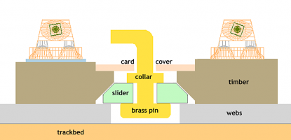
Are you referring to this? If so did the slider part get finished? I cant find how to print that anywhere. I am just playing with changing both these timbers from laser cut ply to FDM especially as one of them is the soleplate carrying timber.
cheers
Phil,
 

Attachments

  • switch_drive_ribs2.png
    switch_drive_ribs2.png
    95.4 KB · Views: 34
_______________
message ref: 9716
Hi John you got me there, what is Martin's design? have I missed something in the recent past?
I agree about the cosmetic tie bars, but I think resin maybe better.
cheer
Phil
@Phil G

Hi Phil,

See:

https://85a.uk/templot/club/index.php?threads/experimental-plug-track-continued.673/post-7628

The ribs are currently included in the timbering bases.

I haven't yet done the design for the slider. I do keep saying that this whole project is unfinished -- there is masses of stuff still to do. :)

Martin.
 
_______________
message ref: 9717
Hi Martin,
I do understand and its not an issue, it was John's comments that threw me. I read it as proven system, I was/am aware of the slider ribs. I was just questioning if I had missed the next bit. clearly not.
I have in fact just printed out the two sides of the slider on the Elegoo to see is a hybrid concept will work here. On face value it should not be an issue, may have to create some sort of alignment jig but that's not a big problem there is enough with the alignment jigs already to make something.
cheers
Phil,
 
_______________
message ref: 9718
Hi Stephen,
interesting idea brass soleplates, question how do brass anchor's work with a brass sole bar? Don't they create a dead short?
I was thinking about printing the soleplate timber with the FDM printer, after all an ironed FDM top surface would look similar to steel stole plate so maybe that would work!!
cheers
Phil
without looking, the soleplates in nickel silver are in 2 parts, the switch anchors on the same etch aren't really to do with the soleplates, normally these can be modelled if required with a bit of strip metal.
 
_______________
message ref: 9719
Hi John,
Are you referring to this? If so did the slider part get finished? I cant find how to print that anywhere. I am just playing with changing both these timbers from laser cut ply to FDM especially as one of them is the soleplate carrying timber.
cheers
Phil,

Phil

I assumed this was something I could easily knock up with a strip of copperclad, simple isolation slot in the middle, drill 2 holes and bend up some wire
 
_______________
message ref: 9721
Back
Top